EP0805034B1 - Ink barrier for Fluid reservoir vacuum or pressure line - Google Patents
Ink barrier for Fluid reservoir vacuum or pressure line Download PDFInfo
- Publication number
- EP0805034B1 EP0805034B1 EP97300822A EP97300822A EP0805034B1 EP 0805034 B1 EP0805034 B1 EP 0805034B1 EP 97300822 A EP97300822 A EP 97300822A EP 97300822 A EP97300822 A EP 97300822A EP 0805034 B1 EP0805034 B1 EP 0805034B1
- Authority
- EP
- European Patent Office
- Prior art keywords
- printhead
- ink
- reservoir
- vent
- tube
- Prior art date
- Legal status (The legal status is an assumption and is not a legal conclusion. Google has not performed a legal analysis and makes no representation as to the accuracy of the status listed.)
- Expired - Lifetime
Links
Images


Classifications
-
- B—PERFORMING OPERATIONS; TRANSPORTING
- B41—PRINTING; LINING MACHINES; TYPEWRITERS; STAMPS
- B41J—TYPEWRITERS; SELECTIVE PRINTING MECHANISMS, i.e. MECHANISMS PRINTING OTHERWISE THAN FROM A FORME; CORRECTION OF TYPOGRAPHICAL ERRORS
- B41J2/00—Typewriters or selective printing mechanisms characterised by the printing or marking process for which they are designed
- B41J2/005—Typewriters or selective printing mechanisms characterised by the printing or marking process for which they are designed characterised by bringing liquid or particles selectively into contact with a printing material
- B41J2/01—Ink jet
- B41J2/17—Ink jet characterised by ink handling
- B41J2/175—Ink supply systems ; Circuit parts therefor
- B41J2/17503—Ink cartridges
- B41J2/17556—Means for regulating the pressure in the cartridge
-
- B—PERFORMING OPERATIONS; TRANSPORTING
- B41—PRINTING; LINING MACHINES; TYPEWRITERS; STAMPS
- B41J—TYPEWRITERS; SELECTIVE PRINTING MECHANISMS, i.e. MECHANISMS PRINTING OTHERWISE THAN FROM A FORME; CORRECTION OF TYPOGRAPHICAL ERRORS
- B41J2/00—Typewriters or selective printing mechanisms characterised by the printing or marking process for which they are designed
- B41J2/005—Typewriters or selective printing mechanisms characterised by the printing or marking process for which they are designed characterised by bringing liquid or particles selectively into contact with a printing material
- B41J2/01—Ink jet
- B41J2/17—Ink jet characterised by ink handling
- B41J2/175—Ink supply systems ; Circuit parts therefor
- B41J2/17503—Ink cartridges
- B41J2/17506—Refilling of the cartridge
- B41J2/17509—Whilst mounted in the printer
-
- B—PERFORMING OPERATIONS; TRANSPORTING
- B41—PRINTING; LINING MACHINES; TYPEWRITERS; STAMPS
- B41J—TYPEWRITERS; SELECTIVE PRINTING MECHANISMS, i.e. MECHANISMS PRINTING OTHERWISE THAN FROM A FORME; CORRECTION OF TYPOGRAPHICAL ERRORS
- B41J2/00—Typewriters or selective printing mechanisms characterised by the printing or marking process for which they are designed
- B41J2/005—Typewriters or selective printing mechanisms characterised by the printing or marking process for which they are designed characterised by bringing liquid or particles selectively into contact with a printing material
- B41J2/01—Ink jet
- B41J2/17—Ink jet characterised by ink handling
- B41J2/175—Ink supply systems ; Circuit parts therefor
- B41J2/17593—Supplying ink in a solid state
-
- B—PERFORMING OPERATIONS; TRANSPORTING
- B41—PRINTING; LINING MACHINES; TYPEWRITERS; STAMPS
- B41J—TYPEWRITERS; SELECTIVE PRINTING MECHANISMS, i.e. MECHANISMS PRINTING OTHERWISE THAN FROM A FORME; CORRECTION OF TYPOGRAPHICAL ERRORS
- B41J2/00—Typewriters or selective printing mechanisms characterised by the printing or marking process for which they are designed
- B41J2/005—Typewriters or selective printing mechanisms characterised by the printing or marking process for which they are designed characterised by bringing liquid or particles selectively into contact with a printing material
- B41J2/01—Ink jet
- B41J2/17—Ink jet characterised by ink handling
- B41J2/19—Ink jet characterised by ink handling for removing air bubbles
-
- B—PERFORMING OPERATIONS; TRANSPORTING
- B41—PRINTING; LINING MACHINES; TYPEWRITERS; STAMPS
- B41J—TYPEWRITERS; SELECTIVE PRINTING MECHANISMS, i.e. MECHANISMS PRINTING OTHERWISE THAN FROM A FORME; CORRECTION OF TYPOGRAPHICAL ERRORS
- B41J2/00—Typewriters or selective printing mechanisms characterised by the printing or marking process for which they are designed
- B41J2/005—Typewriters or selective printing mechanisms characterised by the printing or marking process for which they are designed characterised by bringing liquid or particles selectively into contact with a printing material
- B41J2/01—Ink jet
- B41J2/17—Ink jet characterised by ink handling
- B41J2/195—Ink jet characterised by ink handling for monitoring ink quality
-
- B—PERFORMING OPERATIONS; TRANSPORTING
- B41—PRINTING; LINING MACHINES; TYPEWRITERS; STAMPS
- B41J—TYPEWRITERS; SELECTIVE PRINTING MECHANISMS, i.e. MECHANISMS PRINTING OTHERWISE THAN FROM A FORME; CORRECTION OF TYPOGRAPHICAL ERRORS
- B41J25/00—Actions or mechanisms not otherwise provided for
- B41J25/304—Bodily-movable mechanisms for print heads or carriages movable towards or from paper surface
Definitions
- This invention relates to barriers for preventing ink from escaping from an ink reservoir to which a vacuum or pressure line is connected.
- an ink jet printhead contains a reservoir from which ink is supplied to pressure chambers for ejecting ink drops through an array of orifices in response to drop-ejecting signals.
- air is drawn into the reservoir through a vent.
- a small negative pressure is usually applied to the reservoir vent and, to purge contaminated ink from the ink jet orifices, a positive pressure is applied to the vent.
- an ink jet printhead must be arranged to operate in different orientations, e.g. with the array of orifices aligned in a generally horizontal direction and ejecting drops in a generally horizontal direction, or with the array of orifices aligned in a generally vertical direction and oriented to eject drops horizontally or with the array of orifices aligned in a generally horizontal direction and oriented to eject drops vertically in the downward direction.
- care must be taken to prevent ink from flowing into the reservoir vent or the associated pressure or vacuum line not only in each of the orientations during normal use, but also when the ink jet printhead is completely inverted or shaken during handling.
- the Yuki et al. Patent No. 4,648,273 provides a labyrinth passage containing spaced barrier walls leading to a chamber from which the vent opens to the atmosphere.
- a U-shaped air path extends between an ink reservoir and a vent for the purpose of trapping impurities in the air entering the vent before it reaches the reservoir.
- the Cowger et al. Patent No. 4,931,811 shows labyrinthine spiral and U-shaped paths intended to isolate a liquid valve from the atmosphere and from an ink reservoir, respectively.
- the U-shaped paths have a dimension small enough that ink will form a complete meniscus across the cross-section at any location in the passage so that the portion of the passage receiving ink is completely filled with ink. Moreover, the passage is long enough so that any ink which has been drawn into the ink passage will flow back into the ink jet reservoir when the pressure in the reservoir is reduced. None of the prior art, however, discloses a reservoir arrangement for preventing ink from a reservoir to escape through a vent or vacuum or pressure line connected to the reservoir when the printhead is oriented in any of three mutually orthogonal orientations.
- Another object to the invention is to provide an ink barrier for a reservoir vent connected to a vacuum or pressure line which permits the printhead to be positioned in any of three mutually orthogonal orientations without allowing ink to escape through the vacuum or pressure line.
- a tube having the features set out in claim 1 will be referred to as a U-shaped tube or U-tube.
- the inner diameter of the passage within the U-tube may advantageously be small enough to cause the ink to form a plug, preventing passage of air.
- the ink reservoir of the present invention is intended for use in an ink jet printing system such as described in United States Patent No. 5,489,925 in which an ink jet printhead may be operated in any of three mutually orthogonal orientations.
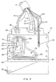
- a typical ink jet system of that type shown in Fig. 1, includes a main control unit 10 containing a remote ink supply reservoir 12 which is connected through an ink supply conduit 14 in a cable 15 to an ink jet printhead 16 and a pressure control unit 18 which is connected to the ink jet printhead 16 through an air conduit 19, also carried by the cable 15.
- the main control unit 10 includes a temperature control unit 22 for controlling the temperature of hot melt ink in various portions of the ink jet system.
- the printhead 16 is movably supported on a vertically disposed column 24 so as to be locked by a clamp 26 at any desired vertical position on the column.
- the printhead 16 is supported for pivotal motion in any vertical plane by a clampable universal joint 28 so that the printhead can be oriented to permit a linear array of ink jet orifices 30 therein, best seen in Fig. 2, to project ink horizontally, either in a horizontal line or in a vertical line, or downwardly.
- the line of orifices 30 is inclined at an angle to the direction of motion of objects which are to receive an image in order to increase the image resolution, i.e., decrease the adjacent line spacing in the image.
- the objects to be printed pass in a generally horizontal direction with respect to the orientation of the printhead 16 shown in Fig. 2, but the angular orientation of the printhead may be varied to increase or decrease the resolution.
- the printhead is disposed with the surface containing the printhead orifices 30 (shown in Fig. 2) in a horizontal orientation as shown in solid lines to cause the orifices to project a train of ink drops 31 downwardly onto the top surfaces 32 of a series of containers 34 which are conveyed in the horizontal direction by a conveyor 36, thus permitting appropriate information to be printed on the top surface of each of the containers.
- the printhead can be lowered on the column 24 and the universal joint 28 can be arranged to clamp the head 16 in an orientation corresponding to that shown in Fig. 2 but with the array of orifices 30 facing the near sides 37 of the containers 34, so as to cause information to be printed on the near side of each of the containers as they are conveyed past the printhead by the conveyor 36.
- the printing system of the invention may be arranged to print a series of labels 38 conveyed on a tape 40 in a vertical direction from one reel 42 to another reel 44 by adjusting the universal joint 28 t6 clamp the printhead in a vertical orientation, as shown in dotted outline in Fig. 1, so that the array of orifices 30 faces the labels 38 as they are conveyed in the vertical direction.
- the temperature control unit 22 is arranged to control the heater 50 so as to heat the block of hot melt ink 48 sufficiently to melt it and to maintain the ink in the supply reservoir 12 at a temperature just above its melting point so that it is sufficiently liquid that it can be transferred by a pump 53 through the supply conduit 14 to the printhead 16 as required.
- the ink temperature in the supply reservoir 12 is kept low enough so that no appreciable degradation will take place even though the ink is maintained continuously at that temperature for several days or weeks.
- the ink supply conduit 14 contains a thermostatically controlled heater 54 connected through a line 56 to the temperature control unit 22 so that the ink in the supply line is also maintained continuously in liquid condition, but at a temperature low enough that no appreciable degradation occurs.
- the ink jet printhead 16 includes a housing 58 containing a reservoir 60 in the form of an internal cavity 61 in the housing 58 which receives ink through the supply conduit 14 for replenishment when necessary.
- the supply conduit is connected to a filter 62 inserted in an internal passage 64 which communicates with the reservoir cavity 61.
- a heater element 66 received in a cylindrical recess 67 in the housing is connected through lines 68 in the cable 15 to the temperature control unit 22 and, to avoid overheating, a thermal fuse assembly 69 connected through corresponding lines 70 to the temperature control unit 22 is arranged to interrupt the supply of power to the heater 66 in the event of an overheat condition.
- the temperature of the ink in the printhead is maintained at a level determined by a temperature detecting thermistor 71 coupled through lines 72 to the temperature control unit 22.
- a low ink sensor 74 is positioned within the reservoir cavity 61, as shown in Fig. 2, at a location such that it will be covered with ink in any of the three mutually orthogonal printhead orientations described above until the volume of ink within the reservoir has been reduced to approximately one-half to one-third of its normal capacity.
- the low ink sensor 74 sends a signal through corresponding lines 76 to the pump 53 to transfer ink from the supply reservoir 12 to the printhead reservoir 60.
- the reservoir 60 To convey ink from the reservoir 60 to the array of orifices 30 in any of the three mutually orthogonal orientations of the printhead 16, the reservoir 60 includes a triangular passage 78 at one end of the cavity 61 leading to an outlet 80 disposed in spaced relation to a lower corner of the cavity 61.
- the passage 78 thus communicates with the corner of the reservoir cavity which is at the lowest level in any of the three printhead orientations described above with respect to Fig. 1.
- the passage 78 and the outlet 80 are at the lower right front portion of the reservoir 60.
- the outlet 80 leads to a duct 81 which conveys ink to adjacent pressure chambers of the conventional type (not shown) associated with each of the orifices 30 to cause ink drops to be ejected therefrom in response to ink ejection signals in the usual manner.
- the vent 82 enters the reservoir cavity 61 at a location diametrically opposite the triangular passage 78 and the outlet 80, i.e. in the upper left rear portion of the reservoir as seen in Fig. 2.
- the vent 82 is connected to the upper end of one leg 84 of a U-shaped tube 86 which, as best seen in Fig.
- leg 84 extends downwardly from the vent 82 along the rear wall of the reservoir cavity 61 and the lower portion 90 extends along the bottom wall of the reservoir cavity, i.e. below the normal minimum level of ink in the reservoir, while the other leg 88 extends upwardly along the rear wall adjacent to the leg 84 with the end of the leg 88 having an end 92 which is open to the atmosphere within the reservoir.
- the ink level is located below the open end 92 of the U-shaped tube in each of the three printhead orientations described above so that ink will not be caused to enter the open end 92 of the U-shaped tube during normal operation in any of those orientations.
- the maximum level of ink in the reservoir should be controlled so that it is below the open end 92 of the U-shaped tube.
- the printhead could be turned during handling or adjusting so that the open end of the U-shaped tube is below the level of ink or the reservoir could be shaken so that ink enters the open end of the U-shaped tube.
- the inner diameter of the passage in the U-shaped tube is made small enough, i.e. less than about 3 mm diameter, to cause the ink to form a plug, preventing passage of air. In this way, when operation of the printhead draws ink from the reservoir 60, the resulting pressure reduction in the airspace in the reservoir will draw the ink out of the open end 92 of the U-tube and back into the reservoir.
- the length of the U-shaped tube is made great enough so that, if tilting or inversion of the printhead causes the open end 92 of the U-shaped tube to be below the level of the ink in the reservoir, the bottom end 90 of the U-shaped tube which joins the legs 84 and 88 will at the same time be at least partially above the level of the ink in the reservoir. This produces a differential pressure which tends to prevent the ink from passing farther into the tube and avoids siphoning of the ink from the reservoir into the vent and the associated pressure or vacuum line.
- the reservoir 60 has a cavity 61 which is approximately 4.5 cm high, 2.5 cm wide and 2.5 cm deep and a triangular passage 78 which is about 2.5 cm long, 2 cm high at its large end, and 0.3 cm wide.
- the normal capacity of the reservoir is approximately 30 cc and the low ink sensor 74 is positioned to indicate a low ink condition with about 10-15 cc of ink remaining in the reservoir in each of the three orientations described above.
- the triangular passage 78 and the reservoir outlet 80 at the location described above the volume of ink remaining in the reservoir can be reduced to approximately 10% of its normal capacity, i.e. about 3 cc, before air could be drawn into the duct leading to the ink jet orifices 30.
Landscapes
- Engineering & Computer Science (AREA)
- Quality & Reliability (AREA)
- Ink Jet (AREA)
- Particle Formation And Scattering Control In Inkjet Printers (AREA)
Description
- This invention relates to barriers for preventing ink from escaping from an ink reservoir to which a vacuum or pressure line is connected.
- In many ink jet systems, an ink jet printhead contains a reservoir from which ink is supplied to pressure chambers for ejecting ink drops through an array of orifices in response to drop-ejecting signals. As the ink in the reservoir is used, air is drawn into the reservoir through a vent. Moreover, to prevent weeping of ink through the ink jet orifices to which the reservoir is connected, a small negative pressure is usually applied to the reservoir vent and, to purge contaminated ink from the ink jet orifices, a positive pressure is applied to the vent.
- In certain cases, an ink jet printhead must be arranged to operate in different orientations, e.g. with the array of orifices aligned in a generally horizontal direction and ejecting drops in a generally horizontal direction, or with the array of orifices aligned in a generally vertical direction and oriented to eject drops horizontally or with the array of orifices aligned in a generally horizontal direction and oriented to eject drops vertically in the downward direction. In an ink jet printhead adapted for use in such a variety of orientations, however, care must be taken to prevent ink from flowing into the reservoir vent or the associated pressure or vacuum line not only in each of the orientations during normal use, but also when the ink jet printhead is completely inverted or shaken during handling.
- In order to prevent ink from reaching a reservoir vent, the Yuki et al. Patent No. 4,648,273 provides a labyrinth passage containing spaced barrier walls leading to a chamber from which the vent opens to the atmosphere. In the Deur et al. Patents Nos. 5,276,468 and 5,386,224, a U-shaped air path extends between an ink reservoir and a vent for the purpose of trapping impurities in the air entering the vent before it reaches the reservoir. The Cowger et al. Patent No. 4,931,811 shows labyrinthine spiral and U-shaped paths intended to isolate a liquid valve from the atmosphere and from an ink reservoir, respectively. In that patent the U-shaped paths have a dimension small enough that ink will form a complete meniscus across the cross-section at any location in the passage so that the portion of the passage receiving ink is completely filled with ink. Moreover, the passage is long enough so that any ink which has been drawn into the ink passage will flow back into the ink jet reservoir when the pressure in the reservoir is reduced. None of the prior art, however, discloses a reservoir arrangement for preventing ink from a reservoir to escape through a vent or vacuum or pressure line connected to the reservoir when the printhead is oriented in any of three mutually orthogonal orientations.
- Accordingly, it is an object of the present invention to provide an ink barrier for a reservoir vacuum or pressure line which overcomes the disadvantages to the prior art.
- Another object to the invention is to provide an ink barrier for a reservoir vent connected to a vacuum or pressure line which permits the printhead to be positioned in any of three mutually orthogonal orientations without allowing ink to escape through the vacuum or pressure line.
- These and other objects of the invention are attained by providing a printhead having the features of claims 1 of the accompanying claims and an ink jet system as defined in
claim 12 of the accompanying claims. - In the following description a tube having the features set out in claim 1 will be referred to as a U-shaped tube or U-tube.
In order to make certain that any ink which enters the open end of the U-tube when the reservoir is shaken or inverted during handling will not pass into the vent or the vacuum or pressure line, the inner diameter of the passage within the U-tube may advantageously be small enough to cause the ink to form a plug, preventing passage of air. As a result, when ink is withdrawn from the reservoir during operation of the ink jet head, the resulting reduction of air pressure within the reservoir will draw any ink which has entered the U-tube passage back into the reservoir. - In the accompanying drawings:
- Further objects and advantages of the invention will be apparent from a reading in the following description in conjunction with the accompanying drawings in which:
- Fig. 1 is a schematic view illustrating a representative embodiment of ink jet printhead containing a reservoir with an ink barrier in accordance with the invention;
- Fig. 2 is a perspective side view of the ink jet printhead of Fig. 1 with one wall of the reservoir removed to illustrate the interior arrangement thereof; and
- Fig. 3 is a perspective exploded view of the arrangement shown in Fig. 2 illustrating the components which are assembled to produce the reservoir arrangement.
-
- The ink reservoir of the present invention is intended for use in an ink jet printing system such as described in United States Patent No. 5,489,925 in which an ink jet printhead may be operated in any of three mutually orthogonal orientations. A typical ink jet system of that type, shown in Fig. 1, includes a
main control unit 10 containing a remoteink supply reservoir 12 which is connected through anink supply conduit 14 in acable 15 to anink jet printhead 16 and apressure control unit 18 which is connected to theink jet printhead 16 through anair conduit 19, also carried by thecable 15. In addition, themain control unit 10 includes atemperature control unit 22 for controlling the temperature of hot melt ink in various portions of the ink jet system. - To facilitate positioning of the
printhead 16 adjacent to different types of objects to which printing is to be applied, the printhead is movably supported on a vertically disposedcolumn 24 so as to be locked by aclamp 26 at any desired vertical position on the column. In addition, theprinthead 16 is supported for pivotal motion in any vertical plane by a clampable universal joint 28 so that the printhead can be oriented to permit a linear array ofink jet orifices 30 therein, best seen in Fig. 2, to project ink horizontally, either in a horizontal line or in a vertical line, or downwardly. - In accordance with conventional practice, the line of
orifices 30 is inclined at an angle to the direction of motion of objects which are to receive an image in order to increase the image resolution, i.e., decrease the adjacent line spacing in the image. In the arrangement shown in the drawings, the objects to be printed pass in a generally horizontal direction with respect to the orientation of theprinthead 16 shown in Fig. 2, but the angular orientation of the printhead may be varied to increase or decrease the resolution. In making such orientation adjustments, however, care should be exercised to make certain that theopen end 92 of the U-shaped tube discussed hereinafter is above the level of the ink in the reservoir. - In the arrangement illustrated in Fig. 1, the printhead is disposed with the surface containing the printhead orifices 30 (shown in Fig. 2) in a horizontal orientation as shown in solid lines to cause the orifices to project a train of ink drops 31 downwardly onto the
top surfaces 32 of a series ofcontainers 34 which are conveyed in the horizontal direction by aconveyor 36, thus permitting appropriate information to be printed on the top surface of each of the containers. If desired, as shown in dotted lines in Fig 1, the printhead can be lowered on thecolumn 24 and theuniversal joint 28 can be arranged to clamp thehead 16 in an orientation corresponding to that shown in Fig. 2 but with the array oforifices 30 facing thenear sides 37 of thecontainers 34, so as to cause information to be printed on the near side of each of the containers as they are conveyed past the printhead by theconveyor 36. - In still another printhead position, the printing system of the invention may be arranged to print a series of
labels 38 conveyed on atape 40 in a vertical direction from onereel 42 to anotherreel 44 by adjusting theuniversal joint 28 t6 clamp the printhead in a vertical orientation, as shown in dotted outline in Fig. 1, so that the array oforifices 30 faces thelabels 38 as they are conveyed in the vertical direction. - The
ink supply reservoir 12 in themain control unit 10, which has asealing cover 46, is arranged to receive ablock 48 of solid hot melt ink and has a thermostatically controlledheater 50 connected by aline 52 to thetemperature control unit 22. Thetemperature control unit 22 is arranged to control theheater 50 so as to heat the block ofhot melt ink 48 sufficiently to melt it and to maintain the ink in thesupply reservoir 12 at a temperature just above its melting point so that it is sufficiently liquid that it can be transferred by apump 53 through thesupply conduit 14 to theprinthead 16 as required. At the same time, the ink temperature in thesupply reservoir 12 is kept low enough so that no appreciable degradation will take place even though the ink is maintained continuously at that temperature for several days or weeks. Similarly, theink supply conduit 14 contains a thermostatically controlledheater 54 connected through aline 56 to thetemperature control unit 22 so that the ink in the supply line is also maintained continuously in liquid condition, but at a temperature low enough that no appreciable degradation occurs. - As shown in Figs. 2 and 3, the
ink jet printhead 16 includes ahousing 58 containing areservoir 60 in the form of aninternal cavity 61 in thehousing 58 which receives ink through thesupply conduit 14 for replenishment when necessary. As shown in Fig. 3, the supply conduit is connected to afilter 62 inserted in an internal passage 64 which communicates with thereservoir cavity 61. - In order to heat hot melt ink contained in the reservoir, a
heater element 66 received in a cylindrical recess 67 in the housing is connected throughlines 68 in thecable 15 to thetemperature control unit 22 and, to avoid overheating, athermal fuse assembly 69 connected throughcorresponding lines 70 to thetemperature control unit 22 is arranged to interrupt the supply of power to theheater 66 in the event of an overheat condition. The temperature of the ink in the printhead is maintained at a level determined by a temperature detecting thermistor 71 coupled throughlines 72 to thetemperature control unit 22. - In order to detect a low ink condition in the
reservoir 60, and thereby initiate replenishment through theline 14, alow ink sensor 74 is positioned within thereservoir cavity 61, as shown in Fig. 2, at a location such that it will be covered with ink in any of the three mutually orthogonal printhead orientations described above until the volume of ink within the reservoir has been reduced to approximately one-half to one-third of its normal capacity. When that condition occurs, thelow ink sensor 74 sends a signal throughcorresponding lines 76 to thepump 53 to transfer ink from thesupply reservoir 12 to theprinthead reservoir 60. - To convey ink from the
reservoir 60 to the array oforifices 30 in any of the three mutually orthogonal orientations of theprinthead 16, thereservoir 60 includes atriangular passage 78 at one end of thecavity 61 leading to anoutlet 80 disposed in spaced relation to a lower corner of thecavity 61. Thepassage 78 thus communicates with the corner of the reservoir cavity which is at the lowest level in any of the three printhead orientations described above with respect to Fig. 1. As seen in Fig. 2, thepassage 78 and theoutlet 80 are at the lower right front portion of thereservoir 60. Theoutlet 80 leads to aduct 81 which conveys ink to adjacent pressure chambers of the conventional type (not shown) associated with each of theorifices 30 to cause ink drops to be ejected therefrom in response to ink ejection signals in the usual manner. - Thus, when the printhead is in the vertical orientation illustrated in Fig. 2 and facing the
surface 37 of apackage 34 as shown in dotted lines in Fig. 1, the lower portions of thepassage 78 and theoutlet 80 are in line with the lower part of thereservoir cavity 61. Moreover, when the printhead is in the horizontal orientation shown in solid lines in Fig. 1, i.e., with theorifices 30 facing the top of apackage 34, thepassage 78 and theoutlet 80 are also at a location corresponding to the lower part of thereservoir cavity 61. Finally, when the printhead is pivoted upwardly from the orientation shown in solid lines in Fig. 1 to face thelabels 38 on thetape 40 as shown in dotted lines in Fig. 1, thepassage 78 and theoutlet 80 are located below the level of ink in thereservoir cavity 61. - As ink is used during the operation of the printhead, the level of the ink in the reservoir falls and, as a result, air is drawn into the reservoir through a
vent 82 which is connected through theline 19 to thepressure control unit 18 in thecontrol unit 10. In accordance with the invention, thevent 82 enters thereservoir cavity 61 at a location diametrically opposite thetriangular passage 78 and theoutlet 80, i.e. in the upper left rear portion of the reservoir as seen in Fig. 2. Within the reservoir cavity thevent 82 is connected to the upper end of oneleg 84 of a U-shapedtube 86 which, as best seen in Fig. 3, consists of an upper portion with twoparallel legs lower portion 90 connecting thelegs leg 84 extends downwardly from thevent 82 along the rear wall of thereservoir cavity 61 and thelower portion 90 extends along the bottom wall of the reservoir cavity, i.e. below the normal minimum level of ink in the reservoir, while theother leg 88 extends upwardly along the rear wall adjacent to theleg 84 with the end of theleg 88 having anend 92 which is open to the atmosphere within the reservoir. - When the
printhead reservoir 60 is in its normally full condition after having been filled with ink from the remoteink supply reservoir 12, the ink level is located below theopen end 92 of the U-shaped tube in each of the three printhead orientations described above so that ink will not be caused to enter theopen end 92 of the U-shaped tube during normal operation in any of those orientations. As previously mentioned, if the angular position of the printhead is changed to vary the angle of the line oforifices 30 with respect to the direction of motion of the objects to be printed, the maximum level of ink in the reservoir should be controlled so that it is below theopen end 92 of the U-shaped tube. - Nevertheless, it is possible that the printhead could be turned during handling or adjusting so that the open end of the U-shaped tube is below the level of ink or the reservoir could be shaken so that ink enters the open end of the U-shaped tube. In order to prevent ink which thus enters the U-shaped tube from being drawn into the vacuum and
pressure line 19 connected to thevent 82, the inner diameter of the passage in the U-shaped tube is made small enough, i.e. less than about 3 mm diameter, to cause the ink to form a plug, preventing passage of air. In this way, when operation of the printhead draws ink from thereservoir 60, the resulting pressure reduction in the airspace in the reservoir will draw the ink out of theopen end 92 of the U-tube and back into the reservoir. - Moreover, the length of the U-shaped tube is made great enough so that, if tilting or inversion of the printhead causes the
open end 92 of the U-shaped tube to be below the level of the ink in the reservoir, thebottom end 90 of the U-shaped tube which joins thelegs - In a typical reservoir arrangement in accordance with the invention, the
reservoir 60 has acavity 61 which is approximately 4.5 cm high, 2.5 cm wide and 2.5 cm deep and atriangular passage 78 which is about 2.5 cm long, 2 cm high at its large end, and 0.3 cm wide. In this case, the normal capacity of the reservoir is approximately 30 cc and thelow ink sensor 74 is positioned to indicate a low ink condition with about 10-15 cc of ink remaining in the reservoir in each of the three orientations described above. Moreover, with thetriangular passage 78 and thereservoir outlet 80 at the location described above, the volume of ink remaining in the reservoir can be reduced to approximately 10% of its normal capacity, i.e. about 3 cc, before air could be drawn into the duct leading to theink jet orifices 30.
Claims (15)
- A printhead (16) for an ink jet printer comprising:-an array of orifices (30) for ejecting ink drops (31) in a selected direction;support means (24, 26, 28) by which the printhead may be supported in at least two orthogonal orientations;a reservoir for supplying ink to the array of orifices in the printhead and having an ink outlet (80) which is located in a lower portion of the reservoir (60) when the printhead is oriented in each of the orthogonal orientations; in which it may be supported;a vent (82) for supplying air to the reservoir; anda tube (86) having two substantially parallel portions (84,88), one of the substantially parallel portions (84) being connected to the vent and the other of the substantially parallel portions (88) having an end (92) which is located above a maximum level of ink in the reservoir when the printhead is in each of its orthogonal orientations, the tube (86) also having a central portion (90) joining the substantially parallel portions (84,88) and extending below a minimum level of ink in the reservoir in each of the orthogonal orientations, of the printhead.
- The printhead of claim 1, including a pressure control line (19) for applying a controlled negative or positive pressure to the vent (82).
- The printhead of claim 1 or 2, including low ink sensor means (74) disposed within the reservoir (60) at a location selected to indicate a low ink condition when the reservoir is orientated in each of the orthogonal orientations.
- The printhead of claim 3, wherein the low ink sensor means (74) is disposed within the reservoir (60) at a location selected to indicate a low ink condition in each of the orthogonal orientations when the reservoir is between about one-third and one-half full
- The printhead of any preceding claim, including an ink supply passage (64) in the printhead for supplying ink to the reservoir cavity (61) and a cylindrical filter (62) received in the supply passage (64).
- The printhead of any preceding claim including heater means (66) for heating ink in the printhead (16) and temperature detector means (71) for detecting the temperature of the printhead and permitting the heater (66) means to be controlled in accordance therewith.
- The printhead of claim 6, including thermal fuse means (69) for disabling the heater means (66) in response to an excessive temperature condition in the printhead (16).
- The printhead of any preceding claim wherein the support means (24,26,28) is arranged to support the printhead in any three mutually orthogonal directions;
- The printhead of any preceding claim, wherein tube (86) has an internal diameter of no more than about 3 mm.
- The printhead of any preceding claim, wherein the substantially parallel portions (84,88) of the tube (86) extend along a first wall of the reservoir (60) and the central portion (90) extends along a second wall of the reservoir toward a wall of the reservoir opposite to the first wall.
- The printhead of claim 10 wherein the central portion (90) of the tube (86) is disposed so as to extend above the maximum level of the ink in the reservoir (60) when the printhead is inverted with respect to each of the orthogonal orientations.
- An ink jet system comprising an ink jet printhead as claimed in any preceding claim and a remote ink supply (12) connected to the printhead reservoir (60).
- An ink jet system according to claim 12 wherein the printhead is as defined in claim 4, and further comprising means for causing the remote ink supply (12) to supply ink to the printhead reservoir (60) when a low level condition is detected by the sensor means (74).
- The system of claim 12 or 13, including pressure control means (118) for producing positive or negative pressure and a vacuum or pressure line connecting the reservoir vent to the pressure control means.
- The jet system of claims 12, 13 or 14, including temperature control means (22) for controlling the temperature of the ink in the reservoir at a desired level.
Applications Claiming Priority (2)
| Application Number | Priority Date | Filing Date | Title |
|---|---|---|---|
| US08/641,109 US5920332A (en) | 1993-05-04 | 1996-04-29 | Ink barrier for fluid reservoir vacuum or pressure line |
| US641109 | 1996-04-29 |
Publications (3)
| Publication Number | Publication Date |
|---|---|
| EP0805034A2 EP0805034A2 (en) | 1997-11-05 |
| EP0805034A3 EP0805034A3 (en) | 1998-05-06 |
| EP0805034B1 true EP0805034B1 (en) | 2002-05-08 |
Family
ID=24570974
Family Applications (1)
| Application Number | Title | Priority Date | Filing Date |
|---|---|---|---|
| EP97300822A Expired - Lifetime EP0805034B1 (en) | 1996-04-29 | 1997-02-07 | Ink barrier for Fluid reservoir vacuum or pressure line |
Country Status (6)
| Country | Link |
|---|---|
| US (1) | US5920332A (en) |
| EP (1) | EP0805034B1 (en) |
| JP (1) | JPH1058710A (en) |
| DE (1) | DE69712402T2 (en) |
| ES (1) | ES2175272T3 (en) |
| GB (1) | GB2312649B (en) |
Families Citing this family (19)
| Publication number | Priority date | Publication date | Assignee | Title |
|---|---|---|---|---|
| JPH1134435A (en) * | 1997-07-18 | 1999-02-09 | Brother Ind Ltd | Power transmission device for inkjet printer |
| GB9910313D0 (en) | 1999-05-05 | 1999-06-30 | Cambridge Consultants | Fluid-pressure controlled ink pressure regulator |
| NL1014294C2 (en) * | 2000-02-04 | 2001-08-07 | Ocu Technologies B V | Melting device and an inkjet printer provided with such a melting device. |
| ES2312151T3 (en) | 2000-10-31 | 2009-02-16 | Zipher Limited | PRINTING DEVICE. |
| US7147313B2 (en) * | 2003-12-30 | 2006-12-12 | Xerox Corporation | Real time detection of ink stick jams in phasing printing systems |
| US7121658B2 (en) | 2004-01-07 | 2006-10-17 | Xerox Corporation | Print head reservoir having purge vents |
| EP1593519B1 (en) * | 2004-05-07 | 2009-06-17 | Panasonic Corporation | Ink supplier for ink jet recorder |
| GB0428480D0 (en) * | 2004-12-30 | 2005-02-02 | Domino Printing Sciences Plc | Improvements in or relating to continuous inkjet printers |
| JP4892308B2 (en) | 2005-10-17 | 2012-03-07 | オセ−テクノロジーズ ビーブイ | Inkjet device with ventilation conduit |
| EP1775131B1 (en) * | 2005-10-17 | 2009-05-13 | Océ-Technologies B.V. | Ink jet device with ventilation conduit |
| US7581827B2 (en) * | 2006-04-26 | 2009-09-01 | Xerox Corporation | System and method for melting solid ink sticks in a phase change ink printer |
| GB2447919B (en) | 2007-03-27 | 2012-04-04 | Linx Printing Tech | Ink jet printing |
| US8052264B2 (en) * | 2008-03-26 | 2011-11-08 | Xerox Corporation | Melting device for increased production of melted ink in a solid ink printer |
| JP2010142995A (en) * | 2008-12-17 | 2010-07-01 | Sii Printek Inc | Rotating device of liquid jetting head, liquid jetting recording apparatus and liquid filling method of the liquid jetting recording apparatus |
| US8024968B2 (en) * | 2009-02-02 | 2011-09-27 | Xerox Corporation | Apparatus and method for detecting ink in a reservoir |
| FR2956061B1 (en) | 2010-02-11 | 2012-12-21 | Markem Imaje | INDUSTRIAL INK JET PRINTER WITH DIGITAL COMMUNICATION |
| US8562091B2 (en) * | 2010-03-09 | 2013-10-22 | Xerox Corporation | Apparatus and method for detecting ink in a reservoir using an overdriven thermistor and an electrical conductor extending from the thermistor |
| JP5645703B2 (en) * | 2011-02-18 | 2014-12-24 | 東芝テック株式会社 | Ink jet head and method of manufacturing ink jet head |
| US11548290B2 (en) | 2020-08-28 | 2023-01-10 | Markem-Imaje Corporation | Systems and techniques for melting hot melt ink in industrial printing systems |
Family Cites Families (25)
| Publication number | Priority date | Publication date | Assignee | Title |
|---|---|---|---|---|
| US3123249A (en) * | 1964-03-03 | Venting arrangements for storage tanks | ||
| US2711252A (en) * | 1951-03-01 | 1955-06-21 | Tested Appliance Company | Dosing means for liquid systems |
| JPS555429B2 (en) * | 1973-09-26 | 1980-02-06 | ||
| US4648273A (en) | 1977-04-22 | 1987-03-10 | Ozols Karlis V | Force responsive device |
| US4370418A (en) * | 1981-07-24 | 1983-01-25 | University Of California | Liquid level control by subsurface draw off |
| US4471364A (en) * | 1982-09-28 | 1984-09-11 | Burroughs Corporation | Ramp style constant head ink jet cartridge |
| US4462307A (en) * | 1983-05-23 | 1984-07-31 | Pet Incorporated | Humpback oven-broiler |
| US4491433A (en) * | 1983-08-29 | 1985-01-01 | Centronics Data Computer Corp. | Venting and ink recycling device |
| JPS60101143U (en) * | 1983-12-16 | 1985-07-10 | シャープ株式会社 | Inkjet printer ink supply device |
| US4709249A (en) * | 1984-06-21 | 1987-11-24 | Canon Kabushiki Kaisha | Ink jet recorder having ink container vent blocking means |
| US4539568A (en) * | 1984-10-15 | 1985-09-03 | Exxon Research And Engineering Co. | Hot melt ink jet having non-spill reservoir |
| US4961081A (en) * | 1987-07-08 | 1990-10-02 | Juki Corporation | Ink feeding mechanism for ink jet printers |
| US4791438A (en) * | 1987-10-28 | 1988-12-13 | Hewlett-Packard Company | Balanced capillary ink jet pen for ink jet printing systems |
| US4938037A (en) * | 1987-12-30 | 1990-07-03 | Carlisle Jr Billy M | Universal accumulator |
| US4931811A (en) * | 1989-01-31 | 1990-06-05 | Hewlett-Packard Company | Thermal ink jet pen having a feedtube with improved sizing and operational with a minimum of depriming |
| US4931812A (en) * | 1989-07-18 | 1990-06-05 | Hewlett-Packard Company | Flow control system for ink cartridges |
| DE69018003T2 (en) * | 1989-10-20 | 1995-08-24 | Canon Kk | Cartridge with ink reservoir can be set up on a color jet device. |
| US5039999A (en) * | 1990-06-26 | 1991-08-13 | Hewlett-Packard Company | Accumulator and pressure control for ink-ket pens |
| JP3187870B2 (en) * | 1990-08-17 | 2001-07-16 | キヤノン株式会社 | Ink tank and ink jet recording apparatus using the ink tank |
| JP2663077B2 (en) * | 1991-03-25 | 1997-10-15 | テクトロニクス・インコーポレイテッド | Ink supply device |
| US5341160A (en) * | 1991-04-17 | 1994-08-23 | Hewlett-Packard Corporation | Valve for ink-jet pen |
| US5223860A (en) * | 1991-06-17 | 1993-06-29 | Tektronix, Inc. | Apparatus for supplying phase change ink to an ink jet printer |
| US5363130A (en) * | 1991-08-29 | 1994-11-08 | Hewlett-Packard Company | Method of valving and orientation sensitive valve including a liquid for controlling flow of gas into a container |
| JPH064183A (en) * | 1992-06-22 | 1994-01-14 | Sharp Corp | Power source controller for information equipment |
| US5489925A (en) * | 1993-05-04 | 1996-02-06 | Markem Corporation | Ink jet printing system |
-
1996
- 1996-04-29 US US08/641,109 patent/US5920332A/en not_active Expired - Lifetime
-
1997
- 1997-02-07 DE DE69712402T patent/DE69712402T2/en not_active Expired - Lifetime
- 1997-02-07 GB GB9702538A patent/GB2312649B/en not_active Expired - Lifetime
- 1997-02-07 ES ES97300822T patent/ES2175272T3/en not_active Expired - Lifetime
- 1997-02-07 EP EP97300822A patent/EP0805034B1/en not_active Expired - Lifetime
- 1997-04-15 JP JP9097319A patent/JPH1058710A/en not_active Withdrawn
Also Published As
| Publication number | Publication date |
|---|---|
| EP0805034A2 (en) | 1997-11-05 |
| GB9702538D0 (en) | 1997-03-26 |
| DE69712402T2 (en) | 2002-08-29 |
| DE69712402D1 (en) | 2002-06-13 |
| GB2312649A (en) | 1997-11-05 |
| US5920332A (en) | 1999-07-06 |
| ES2175272T3 (en) | 2002-11-16 |
| JPH1058710A (en) | 1998-03-03 |
| GB2312649B (en) | 1999-08-11 |
| EP0805034A3 (en) | 1998-05-06 |
Similar Documents
| Publication | Publication Date | Title |
|---|---|---|
| EP0805034B1 (en) | Ink barrier for Fluid reservoir vacuum or pressure line | |
| US4539568A (en) | Hot melt ink jet having non-spill reservoir | |
| US5187498A (en) | Ink supply container and system | |
| JP4036934B2 (en) | Ink delivery system | |
| CA1299914C (en) | Hot melt ink supply system | |
| JP4094709B2 (en) | Inkjet printer and inkjet printing method | |
| JP3492441B2 (en) | Thermal inkjet printbar valve connector and ink handling system | |
| EP0745482B1 (en) | Continuous refill of spring bag reservoir in an ink-jet printer/plotter | |
| US6164766A (en) | Automatic ink refill system for disposable ink jet cartridges | |
| US6457821B1 (en) | Filter carrier for protecting a filter from being blocked by air bubbles in an inkjet printhead | |
| EP0878308B1 (en) | Method and apparatus for prediction of inkjet printhead lifetime | |
| US6120139A (en) | Ink flow design to provide increased heat removal from an inkjet printhead and to provide for air accumulation | |
| US4658274A (en) | Melt ink jet apparatus with means and method for repriming | |
| JPS61135750A (en) | Ink jet device having improved storage system for using hot melt ink | |
| EP3208094B1 (en) | Determining system and printing fluid cartridge | |
| KR100604493B1 (en) | Method and apparatus for venting an ink container | |
| EP2305476B1 (en) | Vent for an inkjet printhead | |
| EP0875385B1 (en) | An ink delivery that utilizes a separate insertable filter carrier | |
| JP2005096208A (en) | Ink distributor of image forming device | |
| EP0178886B1 (en) | Ink jet apparatus and method of operating the same | |
| EP1095779B1 (en) | Method and apparatus for refilling an ink container | |
| EP0178884A2 (en) | Ink jet apparatus and method of operating the same | |
| JP2000085146A (en) | Liquid ejection device | |
| JPH05246023A (en) | Inkjet printer | |
| JPH0531917A (en) | Ink storage device |
Legal Events
| Date | Code | Title | Description |
|---|---|---|---|
| PUAI | Public reference made under article 153(3) epc to a published international application that has entered the european phase |
Free format text: ORIGINAL CODE: 0009012 |
|
| AK | Designated contracting states |
Kind code of ref document: A2 Designated state(s): DE ES FR IT NL |
|
| PUAL | Search report despatched |
Free format text: ORIGINAL CODE: 0009013 |
|
| AK | Designated contracting states |
Kind code of ref document: A3 Designated state(s): DE ES FR IT NL |
|
| 17P | Request for examination filed |
Effective date: 19981022 |
|
| 17Q | First examination report despatched |
Effective date: 20000419 |
|
| GRAG | Despatch of communication of intention to grant |
Free format text: ORIGINAL CODE: EPIDOS AGRA |
|
| GRAG | Despatch of communication of intention to grant |
Free format text: ORIGINAL CODE: EPIDOS AGRA |
|
| GRAH | Despatch of communication of intention to grant a patent |
Free format text: ORIGINAL CODE: EPIDOS IGRA |
|
| GRAH | Despatch of communication of intention to grant a patent |
Free format text: ORIGINAL CODE: EPIDOS IGRA |
|
| GRAA | (expected) grant |
Free format text: ORIGINAL CODE: 0009210 |
|
| AK | Designated contracting states |
Kind code of ref document: B1 Designated state(s): DE ES FR IT NL |
|
| REF | Corresponds to: |
Ref document number: 69712402 Country of ref document: DE Date of ref document: 20020613 |
|
| ET | Fr: translation filed | ||
| REG | Reference to a national code |
Ref country code: ES Ref legal event code: FG2A Ref document number: 2175272 Country of ref document: ES Kind code of ref document: T3 |
|
| PGFP | Annual fee paid to national office [announced via postgrant information from national office to epo] |
Ref country code: NL Payment date: 20030121 Year of fee payment: 7 |
|
| PLBE | No opposition filed within time limit |
Free format text: ORIGINAL CODE: 0009261 |
|
| 26N | No opposition filed |
Effective date: 20030211 |
|
| PG25 | Lapsed in a contracting state [announced via postgrant information from national office to epo] |
Ref country code: NL Free format text: LAPSE BECAUSE OF NON-PAYMENT OF DUE FEES Effective date: 20040901 |
|
| NLV4 | Nl: lapsed or anulled due to non-payment of the annual fee |
Effective date: 20040901 |
|
| REG | Reference to a national code |
Ref country code: DE Ref legal event code: R082 Ref document number: 69712402 Country of ref document: DE Representative=s name: KADOR & PARTNER, DE |
|
| REG | Reference to a national code |
Ref country code: FR Ref legal event code: CD Owner name: MARKEM-IMAJE CORPORATION Effective date: 20120710 |
|
| REG | Reference to a national code |
Ref country code: ES Ref legal event code: PC2A Owner name: MARKEM-IMAJE CORPORATION Effective date: 20120802 |
|
| REG | Reference to a national code |
Ref country code: DE Ref legal event code: R082 Ref document number: 69712402 Country of ref document: DE Representative=s name: KADOR & PARTNER, DE Effective date: 20120627 Ref country code: DE Ref legal event code: R081 Ref document number: 69712402 Country of ref document: DE Owner name: MARKEM-IMAJE CORP., US Free format text: FORMER OWNER: MARKEM CORP., KEENE, US Effective date: 20120627 Ref country code: DE Ref legal event code: R081 Ref document number: 69712402 Country of ref document: DE Owner name: MARKEM-IMAJE CORP., KEENE, US Free format text: FORMER OWNER: MARKEM CORP., KEENE, N.H., US Effective date: 20120627 |
|
| REG | Reference to a national code |
Ref country code: FR Ref legal event code: PLFP Year of fee payment: 19 |
|
| PGFP | Annual fee paid to national office [announced via postgrant information from national office to epo] |
Ref country code: IT Payment date: 20150225 Year of fee payment: 19 Ref country code: ES Payment date: 20150226 Year of fee payment: 19 |
|
| REG | Reference to a national code |
Ref country code: FR Ref legal event code: PLFP Year of fee payment: 20 |
|
| PGFP | Annual fee paid to national office [announced via postgrant information from national office to epo] |
Ref country code: DE Payment date: 20160226 Year of fee payment: 20 |
|
| PGFP | Annual fee paid to national office [announced via postgrant information from national office to epo] |
Ref country code: FR Payment date: 20160217 Year of fee payment: 20 |
|
| PG25 | Lapsed in a contracting state [announced via postgrant information from national office to epo] |
Ref country code: IT Free format text: LAPSE BECAUSE OF NON-PAYMENT OF DUE FEES Effective date: 20160207 |
|
| REG | Reference to a national code |
Ref country code: DE Ref legal event code: R071 Ref document number: 69712402 Country of ref document: DE |
|
| PG25 | Lapsed in a contracting state [announced via postgrant information from national office to epo] |
Ref country code: ES Free format text: LAPSE BECAUSE OF NON-PAYMENT OF DUE FEES Effective date: 20160208 |