EP0804970A2 - Pistolet de pulvérisation à main pour appareil de nettoyage haute pression - Google Patents
Pistolet de pulvérisation à main pour appareil de nettoyage haute pression Download PDFInfo
- Publication number
- EP0804970A2 EP0804970A2 EP97104296A EP97104296A EP0804970A2 EP 0804970 A2 EP0804970 A2 EP 0804970A2 EP 97104296 A EP97104296 A EP 97104296A EP 97104296 A EP97104296 A EP 97104296A EP 0804970 A2 EP0804970 A2 EP 0804970A2
- Authority
- EP
- European Patent Office
- Prior art keywords
- housing
- spray gun
- hand
- pipe section
- held spray
- Prior art date
- Legal status (The legal status is an assumption and is not a legal conclusion. Google has not performed a legal analysis and makes no representation as to the accuracy of the status listed.)
- Granted
Links
- 239000007921 spray Substances 0.000 title claims abstract description 53
- 238000004140 cleaning Methods 0.000 title claims abstract description 6
- 239000007788 liquid Substances 0.000 claims abstract description 12
- 230000000295 complement effect Effects 0.000 claims description 9
- 210000002445 nipple Anatomy 0.000 claims description 7
- 230000003014 reinforcing effect Effects 0.000 claims description 3
- 238000006073 displacement reaction Methods 0.000 claims 1
- 238000010276 construction Methods 0.000 description 4
- 230000002349 favourable effect Effects 0.000 description 2
- 230000008878 coupling Effects 0.000 description 1
- 238000010168 coupling process Methods 0.000 description 1
- 238000005859 coupling reaction Methods 0.000 description 1
- 238000003780 insertion Methods 0.000 description 1
- 230000037431 insertion Effects 0.000 description 1
- 238000004519 manufacturing process Methods 0.000 description 1
- 230000001105 regulatory effect Effects 0.000 description 1
- 230000002787 reinforcement Effects 0.000 description 1
- 238000005096 rolling process Methods 0.000 description 1
- 238000007789 sealing Methods 0.000 description 1
- 238000003860 storage Methods 0.000 description 1
Images


Classifications
-
- B—PERFORMING OPERATIONS; TRANSPORTING
- B60—VEHICLES IN GENERAL
- B60S—SERVICING, CLEANING, REPAIRING, SUPPORTING, LIFTING, OR MANOEUVRING OF VEHICLES, NOT OTHERWISE PROVIDED FOR
- B60S3/00—Vehicle cleaning apparatus not integral with vehicles
- B60S3/04—Vehicle cleaning apparatus not integral with vehicles for exteriors of land vehicles
- B60S3/045—Other hand-held cleaning arrangements, e.g. with sponges, brushes, scrapers or the like
- B60S3/047—Other hand-held cleaning arrangements, e.g. with sponges, brushes, scrapers or the like using liquid or gas distributing means
-
- B—PERFORMING OPERATIONS; TRANSPORTING
- B05—SPRAYING OR ATOMISING IN GENERAL; APPLYING FLUENT MATERIALS TO SURFACES, IN GENERAL
- B05B—SPRAYING APPARATUS; ATOMISING APPARATUS; NOZZLES
- B05B12/00—Arrangements for controlling delivery; Arrangements for controlling the spray area
- B05B12/002—Manually-actuated controlling means, e.g. push buttons, levers or triggers
-
- B—PERFORMING OPERATIONS; TRANSPORTING
- B05—SPRAYING OR ATOMISING IN GENERAL; APPLYING FLUENT MATERIALS TO SURFACES, IN GENERAL
- B05B—SPRAYING APPARATUS; ATOMISING APPARATUS; NOZZLES
- B05B15/00—Details of spraying plant or spraying apparatus not otherwise provided for; Accessories
- B05B15/60—Arrangements for mounting, supporting or holding spraying apparatus
- B05B15/65—Mounting arrangements for fluid connection of the spraying apparatus or its outlets to flow conduits
- B05B15/652—Mounting arrangements for fluid connection of the spraying apparatus or its outlets to flow conduits whereby the jet can be oriented
-
- B—PERFORMING OPERATIONS; TRANSPORTING
- B05—SPRAYING OR ATOMISING IN GENERAL; APPLYING FLUENT MATERIALS TO SURFACES, IN GENERAL
- B05B—SPRAYING APPARATUS; ATOMISING APPARATUS; NOZZLES
- B05B9/00—Spraying apparatus for discharge of liquids or other fluent material, without essentially mixing with gas or vapour
- B05B9/01—Spray pistols, discharge devices
-
- B—PERFORMING OPERATIONS; TRANSPORTING
- B08—CLEANING
- B08B—CLEANING IN GENERAL; PREVENTION OF FOULING IN GENERAL
- B08B3/00—Cleaning by methods involving the use or presence of liquid or steam
- B08B3/02—Cleaning by the force of jets or sprays
- B08B3/026—Cleaning by making use of hand-held spray guns; Fluid preparations therefor
-
- B—PERFORMING OPERATIONS; TRANSPORTING
- B05—SPRAYING OR ATOMISING IN GENERAL; APPLYING FLUENT MATERIALS TO SURFACES, IN GENERAL
- B05B—SPRAYING APPARATUS; ATOMISING APPARATUS; NOZZLES
- B05B15/00—Details of spraying plant or spraying apparatus not otherwise provided for; Accessories
- B05B15/60—Arrangements for mounting, supporting or holding spraying apparatus
- B05B15/65—Mounting arrangements for fluid connection of the spraying apparatus or its outlets to flow conduits
Definitions
- the invention relates to a hand-held spray gun for a high-pressure cleaning device with a housing, into which a liquid line opens, which is rotatably mounted in the housing about its longitudinal axis.
- Such hand-held spray guns are used in high-pressure cleaners to connect a liquid line coming from a high-pressure cleaning device, which is usually designed in the form of a high-pressure hose, and a dispensing tool, for example a jet pipe.
- a high-pressure cleaning device which is usually designed in the form of a high-pressure hose, and a dispensing tool, for example a jet pipe.
- there are normally closing means in the hand spray gun with which the liquid flow can be interrupted or its strength can be regulated.
- the hand spray gun can be rotated relative to the connected high pressure hose in order to avoid tension.
- a high-pressure hose can be connected to a pipe section stored in the hand-held spray gun via a coupling which enables relative rotation between the pipe section and the high-pressure hose (DE 33 00 290 A1).
- the slewing ring is outside the hand spray gun and is therefore endangered in the harsh operation of a high-pressure cleaning device. Damage can occur in this area.
- the liquid line comprises a tube piece which is rotatably mounted in the housing about its longitudinal axis and which has a connecting part at its free end, with which a matching connecting part of a hose line is turned by mutually rotating the hose line and the pipe section is releasably connectable, and that effective anti-rotation means are provided between the housing and pipe section, which optionally Secure or release the pipe section in the housing against rotation about its longitudinal axis.
- a rotary connection between a pipe section and the hand spray gun is provided in the interior of the housing, and the hose line to be connected is connected to this pipe section.
- This connection is made by a mutual rotation of the pipe section and the hose line.
- anti-rotation means are provided which secure the pipe section against rotation in the housing.
- the connecting part of the pipe section is practically firmly connected to the hand-held spray gun in this rotationally secured state, so that the connection to the hose line can easily be established by a relative rotary movement.
- connection between the hose line and the pipe section can be established outside the housing without any problems.
- the connecting part of the pipe section is a thread, so that the connection between the pipe section and the hose line can be produced by a screw connection.
- a particularly favorable embodiment results if the tube piece is designed as a plug-in component that can be plugged into the housing and is inserted in the inserted position with a subsequent line element of the liquid line, a connection that is freely rotatable about the longitudinal axis of the tube piece and that can be fixed in the axial direction.
- Such a piece of pipe can thus be inserted as a separate component into the hand-held spray gun and then serves as an adapter or connecting part for a flexible hose line which, for example, carries a screw connection.
- a connection possibility for hose lines with different connections can be made available by using different pipe pieces.
- connection can be established by inserting a nipple into a sleeve.
- the axial fixation of the pipe section is effected by a stop which is displaceable on the housing and which engages behind a projection on the pipe section in one position and releases it in another position. This makes it possible to detach the tube piece from the housing and pull it out of the housing simply by moving the stopper if the insertion of another tube piece is desired.
- the stop can be a U-shaped bracket which is mounted on the housing so as to be displaceable transversely to the longitudinal direction of the pipe section and which receives the pipe section between its arms in the inserted state.
- the projection can be formed by an annular shoulder on the tube piece, in a preferred embodiment there is a rolling bearing on the annular shoulder, on which the insertable stop rests. This facilitates the mutual rotation of the pipe section and the housing.
- a hand-held spray gun with a piece of pipe that can be used in the manner described can also be used, without structural changes, to accommodate a flexible hose line directly without the interposition of a pipe piece, if this hose line has corresponding connection means at its end, namely connection means that enable a sealing connection and free rotation .
- a hose line could be used which carries a nipple which can be inserted into a sleeve of the connecting line piece and which also carries a projection against which the stop which is displaceable in the housing can rest.
- a hand-held spray gun constructed in this way either serves for the immediate reception of a suitably adapted flexible hose line or can be provided by using a piece of pipe with a connecting part located outside the housing, which is adapted to different connections of the hose lines used.
- the anti-rotation means which secure the pipe section in the housing against rotation about its longitudinal axis, in order to thereby enable the production of the rotary connection between the pipe section and the hose line, can be designed in very different ways. It can be, for example, clamping means which prevent the free rotation by a frictional connection between the tube piece and the housing. Such jamming could be achieved, for example, by slidably mounted brake elements on the housing, which can be pressed against the pipe section, or by compressing the housing, which in the compressed state rests frictionally on the pipe section.
- the anti-rotation means comprise a displaceable locking element which, in the position which prevents rotation, produces a positive connection between the tube piece and the housing.
- recesses prefferably be provided in the uppermost edge region of the locking element in relation to the cylindrical outer wall in order to produce the positive fit, into which protrusions plunge on the inner wall of the housing.
- it can be reinforcing ribs on the inner wall of the housing.
- the locking element is slidably mounted on the pipe section.
- the pipe section forms an independent component, which also carries this locking element, so that no special structural changes are necessary on the housing itself.
- the locking element is a sleeve which is longitudinally displaceable and non-rotatably mounted on the tube piece and which, in the position preventing rotation, dips into a complementary opening of the housing with a non-circular outer surface.
- the non-circular outer surface and the complementary opening of the housing can preferably have the shape of a polygon, in particular that of a hexagon.
- This non-circular outer surface, which in particular can have the shape of a hexagon can be provided in addition to the rotation lock, which results from the engagement of projections of the housing in recesses of the locking element. This results in a particularly effective anti-rotation lock even in the case in which a housing made of plastic is used, which due to its inherent elasticity may experience minor deformations.
- the complementary opening of the housing has a diameter that enables the tube piece to be inserted into the housing. This ensures that the pipe section can be replaced.
- the connecting part on the pipe section is formed by a cylindrical connecting piece pushed onto the end of the pipe section, which carries a connecting thread and on which the sleeve is mounted so as to be longitudinally displaceable.
- This connector therefore takes on a double function, firstly for establishing the connection to the hose line and secondly with regard to the mounting of the displaceable sleeve of the rotation lock.
- the rotation lock between the sleeve and the pipe section or the connection piece can be achieved by a non-circular cross section of the pipe section or the connection piece and a complementary inner surface of the sleeve, in particular the cross section of the pipe section or the connection piece can have the shape of a polygon.
- the sleeve has a grip profile on its outside, for example in the form of a number of circumferential ribs.
- the pipe section can be arranged in a tubular section of the housing surrounding it at a distance, this section then opens into the remaining part of the housing in which closing valves and connections for jet pipes etc. are arranged.
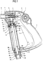
- the hand-held spray gun 1 shown in the drawing comprises a housing consisting of two essentially mirror-symmetrical half-shells 2.
- the housing receives in a top part a central structural unit 4 with a closing valve 5 which can be actuated via a handle 6.
- This handle 6, which is pivotable on Housing is mounted, runs along a handle portion 3 of the housing.
- line means can be connected to the assembly 4, for example a spray lance not shown in the drawing, for this purpose the assembly 4 has a connector 7 with an external thread 8.
- a substantially tubular section 9 of the housing runs essentially parallel to the grip area 3 and is connected at its lower end to the lower end of the grip area 3 via a web 10. At its upper end, the central structural unit 4 opens into this tubular section 9 with a step 11 narrowing bore 11 leading to the closing valve 5.
- the tubular section 9 of the housing communicates with the outside space via an opening 12, this opening 12 is delimited laterally by walls 13 running parallel to the longitudinal axis of the tubular section 9 and has the cross section of a regular hexagon.
- a tubular piece 14 is inserted into the tubular section 9 through the opening 12 and carries at its inserted end a nipple 15 which plunges into the section 16 of the bore 11 with a smaller diameter in a sealed manner.
- the nipple 15 is adjoined by a radially projecting ring shoulder 17, on which a roller bearing 18 surrounding the pipe section 14 rests on the side opposite the nipple.
- This can be fixed in the axial direction between the ring shoulder 17 and a further ring shoulder 19.
- the annular shoulders 17 and 19 and the roller bearing 18 arranged between them dip into the section 20 of the bore 11 with a larger diameter.
- a U-shaped bracket 22 is slidably guided in two parallel bores or notches 21 running transversely to the longitudinal axis of the bore 11, the arms 23 of which, when the bracket 22 is inserted, accommodate the pipe section 14 between them and thereby as a stop for the roller bearing 18 serve.
- the bracket 22 can be pulled out through an opening 24 in the housing, and then it is easily possible to remove the pipe section 14 from the bore 11 and from the tubular section 9 pull out.
- the opening 12 is chosen so large that the pipe section 14 with the annular shoulder 17 and the roller bearing 18 fits through the opening 12.
- the storage described leads to a releasable fixing of the pipe section 14 in the central structural unit 4, in which there is a sealed connection, the pipe section 14 being fixed in the axial direction and remaining freely rotatable about its longitudinal axis.
- the pipe section 14 carries a cylindrical connecting piece 25 with a larger outside diameter, which has an external thread 26 at its lower end, to which one in the drawing Flexible hose, not shown, can be screwed on.
- a hexagonal polygonal region 27 adjoins the external thread 26 toward the housing, on which a sleeve 28 is mounted so as to be longitudinally displaceable.
- This sleeve 28 surrounds the polygonal region 27 tightly, so that the sleeve 28 is rotatably mounted relative to the polygonal region 27.
- the outer surface of the sleeve 28 is divided into four sections, namely a handle region 29 remote from the housing with circumferential ribs 30, an adjoining polygonal region 31 which is designed to be complementary and exactly matching the cross section of the opening 12 of the housing, and an adjoining circular cylindrical element close to the housing Area 32, the outer diameter of which is selected such that it can be freely rotated when it enters the opening 12, and a recess area 33 in which recesses 34, 35 which radially recess relative to the circular cylindrical area 32 are provided (FIG. 4).
- the recesses 34 are formed by lateral flattening, the recesses 35 by an essentially concentric recess with lateral boundary walls 36.
- the sleeve 28 can be moved on the connector 25 between a position remote from the housing and a position close to the housing. In the position remote from the housing, the area 32 plunges into the opening 12, the tube piece can thereby be freely rotated in the housing of the hand-held spray gun 1, nevertheless the sleeve 28 closes the opening 12 to the outside.
- the polygonal region 31 dips into the opening 12 and thereby establishes a rotationally fixed connection between the housing of the hand-held spray gun 1 and the sleeve 28.
- the sleeve 28 is further positioned such that reinforcing ribs 37 arranged on the inner wall of the half-shells 2 and projecting into the interior engage in the recesses 35, while transverse walls 38 of the half-shells 2 engage in the recesses 34 (FIG. 3). This also results in a rotation lock between the sleeve 28 and the housing, which, in addition to the rotation lock, ensures secure rotation fixation by the engagement of the polygonal region 31 in the opening 12.
- the sleeve 28 can also be used to prevent rotation if the user wants to avoid the rotatability of the hand-held spray gun 1 relative to the pipe section 14 and the hose line connected to it for other reasons, this sleeve 28 therefore gives the option of optionally switching the rotation lock on or off.
Landscapes
- Engineering & Computer Science (AREA)
- Mechanical Engineering (AREA)
- Nozzles (AREA)
- Cleaning By Liquid Or Steam (AREA)
- Details Or Accessories Of Spraying Plant Or Apparatus (AREA)
- Detergent Compositions (AREA)
Applications Claiming Priority (2)
| Application Number | Priority Date | Filing Date | Title |
|---|---|---|---|
| DE19617417A DE19617417A1 (de) | 1996-05-01 | 1996-05-01 | Handspritzpistole für ein Hochdruckreinigungsgerät |
| DE19617417 | 1996-05-01 |
Publications (3)
| Publication Number | Publication Date |
|---|---|
| EP0804970A2 true EP0804970A2 (fr) | 1997-11-05 |
| EP0804970A3 EP0804970A3 (fr) | 1998-08-12 |
| EP0804970B1 EP0804970B1 (fr) | 2002-09-04 |
Family
ID=7792977
Family Applications (1)
| Application Number | Title | Priority Date | Filing Date |
|---|---|---|---|
| EP97104296A Expired - Lifetime EP0804970B1 (fr) | 1996-05-01 | 1997-03-13 | Pistolet de pulvérisation à main pour appareil de nettoyage haute pression |
Country Status (4)
| Country | Link |
|---|---|
| EP (1) | EP0804970B1 (fr) |
| AT (1) | ATE223261T1 (fr) |
| DE (3) | DE19617417A1 (fr) |
| DK (1) | DK0804970T3 (fr) |
Cited By (2)
| Publication number | Priority date | Publication date | Assignee | Title |
|---|---|---|---|---|
| CN111050923A (zh) * | 2017-09-14 | 2020-04-21 | 瓦格纳喷涂技术有限公司 | 简化的无气喷枪 |
| CN119368352A (zh) * | 2024-12-27 | 2025-01-28 | 宁波美志工具有限公司 | 一种旋转定位调节的喷水枪 |
Families Citing this family (4)
| Publication number | Priority date | Publication date | Assignee | Title |
|---|---|---|---|---|
| IT238406Y1 (it) * | 1997-05-22 | 2000-11-13 | Interpump Group S P A | Pistola spruzzatrice con innesto rapido |
| DE19743094A1 (de) * | 1997-09-30 | 1999-04-01 | Wap Reinigungssysteme | Abschaltpistole für ein Hochdruckreinigungsgerät mit Antiverdreheinrichtung für den Hochdruckschlauch |
| DE20001101U1 (de) | 2000-01-22 | 2000-03-23 | Alfred Kärcher GmbH & Co, 71364 Winnenden | Strahlrohr für ein Hochdruckreinigungsgerät |
| US6749628B1 (en) | 2001-05-17 | 2004-06-15 | Advanced Cardiovascular Systems, Inc. | Stent and catheter assembly and method for treating bifurcations |
Family Cites Families (7)
| Publication number | Priority date | Publication date | Assignee | Title |
|---|---|---|---|---|
| DE2426042A1 (de) * | 1974-05-30 | 1975-12-11 | Romeico Gmbh | Waschpistole mit spritzrohr oder waschlanze |
| DE3236913A1 (de) * | 1982-10-06 | 1984-04-12 | Wolfgang 4800 Bielefeld Suttner | Spritzvorrichtung |
| DE3407744C2 (de) * | 1984-03-02 | 1986-01-23 | Alfred Kärcher GmbH & Co, 7057 Winnenden | Handspritzpistole für ein Hochdruckreinigungsgerät |
| FR2658435A1 (fr) * | 1990-02-19 | 1991-08-23 | Marcoulet Joseph | Appareil de douche a plusieurs fonctions. |
| DE4035008C2 (de) * | 1990-02-28 | 1993-10-28 | Suttner Gmbh & Co Kg | Schlauchkupplung für Hochdruckschläuche |
| JP2819005B2 (ja) * | 1994-09-21 | 1998-10-30 | 株式会社喜多村合金製作所 | シャワー装置 |
| DE19508638C2 (de) * | 1995-03-10 | 1997-02-27 | Hansa Metallwerke Ag | Handbrause |
-
1996
- 1996-05-01 DE DE19617417A patent/DE19617417A1/de not_active Withdrawn
- 1996-07-26 DE DE29612977U patent/DE29612977U1/de not_active Expired - Lifetime
-
1997
- 1997-03-13 DE DE59708099T patent/DE59708099D1/de not_active Expired - Lifetime
- 1997-03-13 AT AT97104296T patent/ATE223261T1/de not_active IP Right Cessation
- 1997-03-13 EP EP97104296A patent/EP0804970B1/fr not_active Expired - Lifetime
- 1997-03-13 DK DK97104296T patent/DK0804970T3/da active
Cited By (3)
| Publication number | Priority date | Publication date | Assignee | Title |
|---|---|---|---|---|
| CN111050923A (zh) * | 2017-09-14 | 2020-04-21 | 瓦格纳喷涂技术有限公司 | 简化的无气喷枪 |
| EP3681642A4 (fr) * | 2017-09-14 | 2021-06-09 | Wagner Spray Tech Corporation | Pistolet de pulvérisation simplifié sans air |
| CN119368352A (zh) * | 2024-12-27 | 2025-01-28 | 宁波美志工具有限公司 | 一种旋转定位调节的喷水枪 |
Also Published As
| Publication number | Publication date |
|---|---|
| DE59708099D1 (de) | 2002-10-10 |
| EP0804970B1 (fr) | 2002-09-04 |
| EP0804970A3 (fr) | 1998-08-12 |
| DK0804970T3 (da) | 2002-10-07 |
| ATE223261T1 (de) | 2002-09-15 |
| DE29612977U1 (de) | 1996-09-19 |
| DE19617417A1 (de) | 1997-11-06 |
Similar Documents
| Publication | Publication Date | Title |
|---|---|---|
| DE102008052277B3 (de) | Spenderventilanordnung für ein Gefäß | |
| DE19637074A1 (de) | Kupplungseinrichtung zur Verbindung zweier Rohrelemente | |
| DE2011409B2 (de) | Ventilschnellkupplung für zwei gas- oder flüssigkeitsführende Leitungen | |
| DE4345003C1 (de) | Zahnbürste | |
| DE102005031871B3 (de) | Anschluß-Vorrichtung für einen Wellschlauch | |
| DE4035008C2 (de) | Schlauchkupplung für Hochdruckschläuche | |
| DE4433812C2 (de) | Schlauchanschluß zum Anschluß eines Schlauches, insbesondere eines Gartenschlauches, an einem Anschlußnippel | |
| EP0964493A2 (fr) | Entrée de câble de forme angulaire avec une lieu de séparation entre les deux branches | |
| EP0804970A2 (fr) | Pistolet de pulvérisation à main pour appareil de nettoyage haute pression | |
| EP0859890B1 (fr) | Robinet a usage sanitaire | |
| EP0170042B1 (fr) | Raccord | |
| EP1649111B1 (fr) | Dispositif de retenue pour une douche | |
| DE19545945C1 (de) | Wasserauslaufarmatur mit lösbarem Armaturenkörper | |
| EP3935225A1 (fr) | Douchette de voyage | |
| DE8608406U1 (de) | Transportfaß für Flüssigkeiten, insbesondere für Bier | |
| DE9001274U1 (de) | Vorrichtung zur Kupplung eines unter Druck stehenden Vorratsbehälters mit einer Ausgabeeinrichtung | |
| DE3937278A1 (de) | Vorrichtung fuer auslaufrohr fuer kunststoffkanister | |
| EP0730911A1 (fr) | Douche à main | |
| DE3010404A1 (de) | Feuerloeschgeraet zum anschliessen an haushalt-wasserzapfstellen | |
| DE7219010U (de) | Eckarmatur zum Anschluß flexibler Leitungen | |
| EP1561063A1 (fr) | Douchette a main pour enrouleur de tuyau flexible | |
| DE19831186C2 (de) | Betätigungsvorrichtung für den Arretierstift des Schwenkhebels einer Einrichtung für die Entnahme von Flüssigkeiten unter Druck aus einem Behälter | |
| AT18336U1 (de) | Anschlussstück für Schläuche | |
| DE29809787U1 (de) | Schlauchkupplung | |
| DE8337630U1 (de) | Rohrschelle od.dgl. mit gewindeanschlussteil |
Legal Events
| Date | Code | Title | Description |
|---|---|---|---|
| PUAI | Public reference made under article 153(3) epc to a published international application that has entered the european phase |
Free format text: ORIGINAL CODE: 0009012 |
|
| AK | Designated contracting states |
Kind code of ref document: A2 Designated state(s): AT BE CH DE DK ES FI FR GB GR IE IT LI LU MC NL PT SE |
|
| PUAL | Search report despatched |
Free format text: ORIGINAL CODE: 0009013 |
|
| AK | Designated contracting states |
Kind code of ref document: A3 Designated state(s): AT BE CH DE DK ES FI FR GB GR IE IT LI LU MC NL PT SE |
|
| 17P | Request for examination filed |
Effective date: 19981008 |
|
| 17Q | First examination report despatched |
Effective date: 19990315 |
|
| GRAG | Despatch of communication of intention to grant |
Free format text: ORIGINAL CODE: EPIDOS AGRA |
|
| GRAG | Despatch of communication of intention to grant |
Free format text: ORIGINAL CODE: EPIDOS AGRA |
|
| GRAH | Despatch of communication of intention to grant a patent |
Free format text: ORIGINAL CODE: EPIDOS IGRA |
|
| GRAH | Despatch of communication of intention to grant a patent |
Free format text: ORIGINAL CODE: EPIDOS IGRA |
|
| GRAA | (expected) grant |
Free format text: ORIGINAL CODE: 0009210 |
|
| AK | Designated contracting states |
Kind code of ref document: B1 Designated state(s): AT BE CH DE DK ES FI FR GB GR IE IT LI LU MC NL PT SE |
|
| PG25 | Lapsed in a contracting state [announced via postgrant information from national office to epo] |
Ref country code: NL Free format text: LAPSE BECAUSE OF FAILURE TO SUBMIT A TRANSLATION OF THE DESCRIPTION OR TO PAY THE FEE WITHIN THE PRESCRIBED TIME-LIMIT Effective date: 20020904 Ref country code: IE Free format text: LAPSE BECAUSE OF FAILURE TO SUBMIT A TRANSLATION OF THE DESCRIPTION OR TO PAY THE FEE WITHIN THE PRESCRIBED TIME-LIMIT Effective date: 20020904 Ref country code: GR Free format text: LAPSE BECAUSE OF FAILURE TO SUBMIT A TRANSLATION OF THE DESCRIPTION OR TO PAY THE FEE WITHIN THE PRESCRIBED TIME-LIMIT Effective date: 20020904 Ref country code: FI Free format text: LAPSE BECAUSE OF FAILURE TO SUBMIT A TRANSLATION OF THE DESCRIPTION OR TO PAY THE FEE WITHIN THE PRESCRIBED TIME-LIMIT Effective date: 20020904 |
|
| REF | Corresponds to: |
Ref document number: 223261 Country of ref document: AT Date of ref document: 20020915 Kind code of ref document: T |
|
| REG | Reference to a national code |
Ref country code: GB Ref legal event code: FG4D Free format text: NOT ENGLISH |
|
| REG | Reference to a national code |
Ref country code: CH Ref legal event code: EP |
|
| REG | Reference to a national code |
Ref country code: IE Ref legal event code: FG4D Free format text: GERMAN |
|
| REG | Reference to a national code |
Ref country code: DK Ref legal event code: T3 |
|
| REF | Corresponds to: |
Ref document number: 59708099 Country of ref document: DE Date of ref document: 20021010 |
|
| PG25 | Lapsed in a contracting state [announced via postgrant information from national office to epo] |
Ref country code: SE Free format text: LAPSE BECAUSE OF FAILURE TO SUBMIT A TRANSLATION OF THE DESCRIPTION OR TO PAY THE FEE WITHIN THE PRESCRIBED TIME-LIMIT Effective date: 20021204 |
|
| PG25 | Lapsed in a contracting state [announced via postgrant information from national office to epo] |
Ref country code: PT Free format text: LAPSE BECAUSE OF FAILURE TO SUBMIT A TRANSLATION OF THE DESCRIPTION OR TO PAY THE FEE WITHIN THE PRESCRIBED TIME-LIMIT Effective date: 20021212 |
|
| NLV1 | Nl: lapsed or annulled due to failure to fulfill the requirements of art. 29p and 29m of the patents act | ||
| GBT | Gb: translation of ep patent filed (gb section 77(6)(a)/1977) |
Effective date: 20030115 |
|
| PG25 | Lapsed in a contracting state [announced via postgrant information from national office to epo] |
Ref country code: LU Free format text: LAPSE BECAUSE OF NON-PAYMENT OF DUE FEES Effective date: 20030313 Ref country code: AT Free format text: LAPSE BECAUSE OF NON-PAYMENT OF DUE FEES Effective date: 20030313 |
|
| PG25 | Lapsed in a contracting state [announced via postgrant information from national office to epo] |
Ref country code: ES Free format text: LAPSE BECAUSE OF FAILURE TO SUBMIT A TRANSLATION OF THE DESCRIPTION OR TO PAY THE FEE WITHIN THE PRESCRIBED TIME-LIMIT Effective date: 20030328 |
|
| PG25 | Lapsed in a contracting state [announced via postgrant information from national office to epo] |
Ref country code: MC Free format text: LAPSE BECAUSE OF NON-PAYMENT OF DUE FEES Effective date: 20030331 Ref country code: LI Free format text: LAPSE BECAUSE OF NON-PAYMENT OF DUE FEES Effective date: 20030331 Ref country code: CH Free format text: LAPSE BECAUSE OF NON-PAYMENT OF DUE FEES Effective date: 20030331 Ref country code: BE Free format text: LAPSE BECAUSE OF NON-PAYMENT OF DUE FEES Effective date: 20030331 |
|
| ET | Fr: translation filed | ||
| RAP2 | Party data changed (patent owner data changed or rights of a patent transferred) |
Owner name: ALFRED KAERCHER GMBH & CO. KG |
|
| REG | Reference to a national code |
Ref country code: IE Ref legal event code: FD4D Ref document number: 0804970E Country of ref document: IE |
|
| PLBE | No opposition filed within time limit |
Free format text: ORIGINAL CODE: 0009261 |
|
| STAA | Information on the status of an ep patent application or granted ep patent |
Free format text: STATUS: NO OPPOSITION FILED WITHIN TIME LIMIT |
|
| 26N | No opposition filed |
Effective date: 20030605 |
|
| BERE | Be: lapsed |
Owner name: ALFRED *KARCHER G.M.B.H. & CO. Effective date: 20030331 |
|
| REG | Reference to a national code |
Ref country code: CH Ref legal event code: PL |
|
| PGFP | Annual fee paid to national office [announced via postgrant information from national office to epo] |
Ref country code: DK Payment date: 20140311 Year of fee payment: 18 |
|
| PGFP | Annual fee paid to national office [announced via postgrant information from national office to epo] |
Ref country code: FR Payment date: 20140311 Year of fee payment: 18 Ref country code: IT Payment date: 20140310 Year of fee payment: 18 |
|
| PGFP | Annual fee paid to national office [announced via postgrant information from national office to epo] |
Ref country code: GB Payment date: 20140312 Year of fee payment: 18 |
|
| PGFP | Annual fee paid to national office [announced via postgrant information from national office to epo] |
Ref country code: DE Payment date: 20140430 Year of fee payment: 18 |
|
| REG | Reference to a national code |
Ref country code: DE Ref legal event code: R082 Ref document number: 59708099 Country of ref document: DE Representative=s name: HOEGER, STELLRECHT & PARTNER PATENTANWAELTE MB, DE |
|
| REG | Reference to a national code |
Ref country code: DE Ref legal event code: R119 Ref document number: 59708099 Country of ref document: DE |
|
| REG | Reference to a national code |
Ref country code: DK Ref legal event code: EBP Effective date: 20150331 |
|
| GBPC | Gb: european patent ceased through non-payment of renewal fee |
Effective date: 20150313 |
|
| PG25 | Lapsed in a contracting state [announced via postgrant information from national office to epo] |
Ref country code: IT Free format text: LAPSE BECAUSE OF NON-PAYMENT OF DUE FEES Effective date: 20150313 |
|
| REG | Reference to a national code |
Ref country code: FR Ref legal event code: ST Effective date: 20151130 |
|
| PG25 | Lapsed in a contracting state [announced via postgrant information from national office to epo] |
Ref country code: GB Free format text: LAPSE BECAUSE OF NON-PAYMENT OF DUE FEES Effective date: 20150313 Ref country code: DE Free format text: LAPSE BECAUSE OF NON-PAYMENT OF DUE FEES Effective date: 20151001 |
|
| PG25 | Lapsed in a contracting state [announced via postgrant information from national office to epo] |
Ref country code: FR Free format text: LAPSE BECAUSE OF NON-PAYMENT OF DUE FEES Effective date: 20150331 |
|
| PG25 | Lapsed in a contracting state [announced via postgrant information from national office to epo] |
Ref country code: DK Free format text: LAPSE BECAUSE OF NON-PAYMENT OF DUE FEES Effective date: 20150331 |