EP0804889A2 - Ressort à gaz pour chaise - Google Patents
Ressort à gaz pour chaise Download PDFInfo
- Publication number
- EP0804889A2 EP0804889A2 EP97106443A EP97106443A EP0804889A2 EP 0804889 A2 EP0804889 A2 EP 0804889A2 EP 97106443 A EP97106443 A EP 97106443A EP 97106443 A EP97106443 A EP 97106443A EP 0804889 A2 EP0804889 A2 EP 0804889A2
- Authority
- EP
- European Patent Office
- Prior art keywords
- housing
- piston
- gas spring
- piston rod
- valve
- Prior art date
- Legal status (The legal status is an assumption and is not a legal conclusion. Google has not performed a legal analysis and makes no representation as to the accuracy of the status listed.)
- Granted
Links
Images

Classifications
-
- A—HUMAN NECESSITIES
- A47—FURNITURE; DOMESTIC ARTICLES OR APPLIANCES; COFFEE MILLS; SPICE MILLS; SUCTION CLEANERS IN GENERAL
- A47C—CHAIRS; SOFAS; BEDS
- A47C3/00—Chairs characterised by structural features; Chairs or stools with rotatable or vertically-adjustable seats
- A47C3/20—Chairs or stools with vertically-adjustable seats
- A47C3/30—Chairs or stools with vertically-adjustable seats with vertically-acting fluid cylinder
-
- F—MECHANICAL ENGINEERING; LIGHTING; HEATING; WEAPONS; BLASTING
- F16—ENGINEERING ELEMENTS AND UNITS; GENERAL MEASURES FOR PRODUCING AND MAINTAINING EFFECTIVE FUNCTIONING OF MACHINES OR INSTALLATIONS; THERMAL INSULATION IN GENERAL
- F16F—SPRINGS; SHOCK-ABSORBERS; MEANS FOR DAMPING VIBRATION
- F16F9/00—Springs, vibration-dampers, shock-absorbers, or similarly-constructed movement-dampers using a fluid or the equivalent as damping medium
- F16F9/32—Details
-
- F—MECHANICAL ENGINEERING; LIGHTING; HEATING; WEAPONS; BLASTING
- F16—ENGINEERING ELEMENTS AND UNITS; GENERAL MEASURES FOR PRODUCING AND MAINTAINING EFFECTIVE FUNCTIONING OF MACHINES OR INSTALLATIONS; THERMAL INSULATION IN GENERAL
- F16F—SPRINGS; SHOCK-ABSORBERS; MEANS FOR DAMPING VIBRATION
- F16F9/00—Springs, vibration-dampers, shock-absorbers, or similarly-constructed movement-dampers using a fluid or the equivalent as damping medium
- F16F9/02—Springs, vibration-dampers, shock-absorbers, or similarly-constructed movement-dampers using a fluid or the equivalent as damping medium using gas only or vacuum
- F16F9/0209—Telescopic
- F16F9/0245—Means for adjusting the length of, or for locking, the spring or dampers
Definitions
- the invention relates to a chair gas spring according to the preamble of claim 1.
- the invention is therefore based on the object of designing a chair gas spring of the generic type in such a way that it has a maximum possible height adjustment range in the loaded state.
- the chair column shown in FIG. 1 has a guide tube 2 attached to a base 1, which is provided with a guide bush 3 at its upper open end.
- a gas spring 4 which is adjustable in terms of eyes and the housing 5 of which is arranged so as to be displaceable in the guide bush 3 in the direction of a common central longitudinal axis 6.
- a piston rod 7 is led out of the housing 5 downwards, the free end of which is supported by means of an axial bearing 8 on a base 9 of the guide tube 2 and is fastened thereon by means of a fastening element 10.
- the housing 5 of the gas spring 4 has an outer cylinder 11 and an inner cylinder 12 arranged concentrically therein.
- a piston 14 lies in a sealed manner on the inner wall 13 of the inner cylinder 12, which is attached to the inner end of the piston rod 7.
- the piston 14 divides the inner cylinder 12 into two housing spaces 15, 16.
- the piston rod 7 is guided in the region of its exit from the housing 5 in a guide 17 which is sealed off from the inner wall 18 of the outer cylinder 11 and in which a multiple lip seal 19 is arranged which bears against the piston rod 7.
- the guide 17 is held by means of a flange 20 of the outer cylinder 11. Due to the design described, the gas spring 4 is sealed gas and liquid-tight at the outlet of the piston rod 7.
- a centering ring 21, which bears against the guide 17 and covers the seal 19, is arranged towards the adjacent housing space 15, which, on the one hand, bears against the inner wall 18 of the outer cylinder 11 and is thereby centered on the axis 6 and, on the other hand, one which receives the inner cylinder 12 and the axis 6 centering centering collar 22.
- the inner cylinder 12 is supported on the centering ring 21 in the direction of the axis 6.
- connecting channels 23 are formed which connect the housing space 15 formed between the piston 14 and the piston rod outlet end of the housing 5 to a gap-like annular overflow channel 24 formed between the outer cylinder 11 and the inner cylinder 12.
- a valve 25 is arranged in the housing 5, the valve housing 26 of which rests sealed against the inner wall 18 of the outer cylinder 11 and the inner wall 13 of the inner cylinder 12 and which centers the inner cylinder 12 to the axis 6 by means of a centering collar 27 and which Inner cylinder 12 is supported in the direction of the axis 6.
- the valve housing 26 has a connecting channel 28 connected to the overflow channel 24, which is connected to a connecting space 29 formed concentrically to the axis 6 in the valve housing 26 and which can be connected to the housing space 16 between the valve 25 and the piston 14.
- a valve pin 30 which opens a closing point 30a when pushed in in the direction of the housing space 16 and thus connects the connection space 29 to the housing space 16 and that in it In the rest position shown in the drawing, the closing point 30a closes and thus separates the connecting space from the building space 16.
- the valve pin 30 is led outwards from the valve housing 26 and bears against a slide 31 which is guided and held in a fastening section 32 of the housing 5 in the direction of the axis 6.
- a spacer 33 is arranged in the fastening section 32, which is held by a flange 34 of the outer cylinder 11. This spacer 33 also holds the valve 25 in its axial position.
- the seat support of a chair or armchair can be fastened to this fastening section 32.
- the slider 31 is operated by means of a lever or the like.
- the housing spaces 15, 16 and the connecting channels 23, 28, the connecting space 29 and the overflow channel 24 are filled with compressed gas and possibly some oil.
- the piston rod 7 can spring with the piston 14 relative to the housing 5. If the closing point 30a of the valve 25 is opened by pushing the valve pin 30 in the direction of the housing space 16, then either gas from the housing space 15 through the connecting channels 23, the overflow channel 24, the connecting channel 28 and the connecting space 29 into the housing space 16 or vice versa flow depending on the force acting on the piston rod 7 in the direction of the axis 6.
- the structure of the entire chair column including the gas spring 5 and its mode of operation as a chair gas spring with the exception of the design of the overflow channel 27 are known, for example from the basic DE-PS 18 12 282 (corresponding to US Pat. No. 3,656,593 and JP- PS 846 405).
- the volume V O is formed by the housing space 16, which is delimited by the piston top 36 facing the valve 25 on the one hand and the valve housing 26 to the closing point 30 a on the other and naturally the inner wall 13 of the inner cylinder 12. It applies V O / V U > 10 . Is preferred V O / V U > 20 . It is particularly preferred V O / V U > 30 and even more preferred V O / V U > 40 .
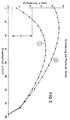
- the described design ensures that the available adjustment length of the gas spring is increased. This is explained, inter alia, using the diagram according to FIG. 2.
Landscapes
- Engineering & Computer Science (AREA)
- General Engineering & Computer Science (AREA)
- Mechanical Engineering (AREA)
- Chairs Characterized By Structure (AREA)
- Fluid-Damping Devices (AREA)
- Absorbent Articles And Supports Therefor (AREA)
Applications Claiming Priority (2)
| Application Number | Priority Date | Filing Date | Title |
|---|---|---|---|
| DE29608147U | 1996-05-04 | ||
| DE29608147U DE29608147U1 (de) | 1996-05-04 | 1996-05-04 | Stuhl-Gasfeder |
Publications (3)
| Publication Number | Publication Date |
|---|---|
| EP0804889A2 true EP0804889A2 (fr) | 1997-11-05 |
| EP0804889A3 EP0804889A3 (fr) | 1999-12-29 |
| EP0804889B1 EP0804889B1 (fr) | 2003-06-18 |
Family
ID=8023569
Family Applications (1)
| Application Number | Title | Priority Date | Filing Date |
|---|---|---|---|
| EP97106443A Expired - Lifetime EP0804889B1 (fr) | 1996-05-04 | 1997-04-18 | Ressort à gaz pour chaise |
Country Status (6)
| Country | Link |
|---|---|
| EP (1) | EP0804889B1 (fr) |
| JP (1) | JPH1061703A (fr) |
| KR (1) | KR100456220B1 (fr) |
| DE (2) | DE29608147U1 (fr) |
| ES (1) | ES2201218T3 (fr) |
| TW (1) | TW349614U (fr) |
Cited By (1)
| Publication number | Priority date | Publication date | Assignee | Title |
|---|---|---|---|---|
| WO2002077497A1 (fr) * | 2001-03-23 | 2002-10-03 | Montajes Mecanicos Lezo, S.L. | Cylindre a gaz a double chemise |
Families Citing this family (3)
| Publication number | Priority date | Publication date | Assignee | Title |
|---|---|---|---|---|
| DE19809389C1 (de) * | 1998-03-05 | 1999-10-07 | Stabilus Gmbh | Längenverstellbare Säule |
| KR100478652B1 (ko) * | 2002-09-10 | 2005-03-23 | 정의협 | 길이 조절 가스 스프링 |
| DE102015209465A1 (de) | 2015-05-22 | 2016-11-24 | Sedus Stoll Ag | Gasfedervorrichtung zur Höhenverstellung eines Stuhls und Stuhl mit einer solchen Gasfedervorrichtung |
Family Cites Families (6)
| Publication number | Priority date | Publication date | Assignee | Title |
|---|---|---|---|---|
| DE1554201B1 (de) * | 1965-02-25 | 1971-07-01 | Fichtel & Sachs Ag | Hydropneumatisches Hubaggregat,insbesondere zur stufenlosen Hoehenverstellung von Tischplatten und Stuehlen |
| DE1812282C3 (de) * | 1968-12-03 | 1981-07-30 | Fritz Bauer + Söhne oHG, 8503 Altdorf | Hubvorrichtung zum stufenlosen Höhenverstellen von Tischplatten, Stuhlsitzen u.dgl. |
| DE2907100A1 (de) * | 1979-02-23 | 1980-08-28 | Bauer Fritz & Soehne Ohg | Laengenverstellbare gasfeder |
| US4834347A (en) * | 1988-04-20 | 1989-05-30 | Grazina J. Pauliukonis | Positioner with large diameter piston rod and fluted volume-compensating piston |
| DE4009034A1 (de) * | 1990-03-21 | 1991-09-26 | Suspa Federungstech | Laengenverstellbare gasfeder |
| DE4420914A1 (de) * | 1994-06-16 | 1995-12-21 | Suspa Compart Ag | Längenverstellbare Gasfeder und längenverstellbare Säule für Stühle, Tische mit einer längenverstellbaren Gasfeder |
-
1996
- 1996-05-04 DE DE29608147U patent/DE29608147U1/de not_active Expired - Lifetime
-
1997
- 1997-04-18 ES ES97106443T patent/ES2201218T3/es not_active Expired - Lifetime
- 1997-04-18 DE DE59710291T patent/DE59710291D1/de not_active Expired - Lifetime
- 1997-04-18 EP EP97106443A patent/EP0804889B1/fr not_active Expired - Lifetime
- 1997-04-28 TW TW086206730U patent/TW349614U/zh unknown
- 1997-04-30 KR KR1019970016525A patent/KR100456220B1/ko not_active Expired - Fee Related
- 1997-05-01 JP JP9113910A patent/JPH1061703A/ja active Pending
Cited By (2)
| Publication number | Priority date | Publication date | Assignee | Title |
|---|---|---|---|---|
| WO2002077497A1 (fr) * | 2001-03-23 | 2002-10-03 | Montajes Mecanicos Lezo, S.L. | Cylindre a gaz a double chemise |
| US6886671B2 (en) | 2001-03-23 | 2005-05-03 | Gain Gas Technique, S.L. | Gas cylinder with a double jacket |
Also Published As
| Publication number | Publication date |
|---|---|
| EP0804889A3 (fr) | 1999-12-29 |
| EP0804889B1 (fr) | 2003-06-18 |
| DE59710291D1 (de) | 2003-07-24 |
| DE29608147U1 (de) | 1996-08-01 |
| TW349614U (en) | 1999-01-01 |
| ES2201218T3 (es) | 2004-03-16 |
| JPH1061703A (ja) | 1998-03-06 |
| KR100456220B1 (ko) | 2005-01-26 |
| KR970075455A (ko) | 1997-12-10 |
Similar Documents
| Publication | Publication Date | Title |
|---|---|---|
| DE3738298C2 (de) | Längenverstellbare Gasfeder für höhenverstellbare Stühle | |
| DE2408052C3 (de) | Längenverstellbare Gasfeder | |
| DE69009754T2 (de) | Dosierventil für aerosolbehälter. | |
| DE69016218T2 (de) | Hydraulisch blockierbare Gasfeder. | |
| DE2164943C3 (de) | Hydraulisch blockierbare Hubvorrichtung | |
| DE2341352C2 (de) | Blockierbares Hubaggregat mit Endfederung | |
| DE19827657A1 (de) | Längenverstellbare Gasfeder | |
| EP1403549A2 (fr) | Ressort à compression réglable en longueur | |
| DE2312445B2 (de) | Hydraulischer Stoßdämpfer | |
| DE3210112A1 (de) | Vorrichtung zum tragen eines sitzes in einer vorbestimmten hoehe | |
| DE3616438A1 (de) | Hydropneumatische verstelleinheit | |
| EP1526301B1 (fr) | Ressort de compression avec une longueur réglable et siège avec un tel ressort | |
| DE1925963A1 (de) | Gasfeder | |
| EP1525144B1 (fr) | Valve de regulation de pression | |
| EP2807963A1 (fr) | Machine à café expresso avec une unité d'infusion | |
| DE10163996A1 (de) | Längenverstellbare Gasfeder | |
| DE7825656U1 (de) | Gasfeder | |
| EP1736682B1 (fr) | Ressort à gaz réglable en longueur | |
| DE2744917A1 (de) | Sitzventil mit geradem durchgang | |
| EP1741843A2 (fr) | Ensemble anti-retour | |
| DE3630911C2 (fr) | ||
| EP1557114B1 (fr) | Colonne de chaise réglable en hauteur | |
| DE9204971U1 (de) | Federelement | |
| EP0804889B1 (fr) | Ressort à gaz pour chaise | |
| DE102007012838B3 (de) | Gasfeder |
Legal Events
| Date | Code | Title | Description |
|---|---|---|---|
| PUAI | Public reference made under article 153(3) epc to a published international application that has entered the european phase |
Free format text: ORIGINAL CODE: 0009012 |
|
| AK | Designated contracting states |
Kind code of ref document: A2 Designated state(s): DE ES FR GB IT |
|
| PUAL | Search report despatched |
Free format text: ORIGINAL CODE: 0009013 |
|
| AK | Designated contracting states |
Kind code of ref document: A3 Designated state(s): DE ES FR GB IT |
|
| RIC1 | Information provided on ipc code assigned before grant |
Free format text: 6A 47C 3/30 A, 6F 16F 9/02 B |
|
| 17P | Request for examination filed |
Effective date: 19991214 |
|
| RAP1 | Party data changed (applicant data changed or rights of an application transferred) |
Owner name: SUSPA HOLDING GMBH |
|
| 17Q | First examination report despatched |
Effective date: 20011003 |
|
| GRAH | Despatch of communication of intention to grant a patent |
Free format text: ORIGINAL CODE: EPIDOS IGRA |
|
| GRAH | Despatch of communication of intention to grant a patent |
Free format text: ORIGINAL CODE: EPIDOS IGRA |
|
| RAP1 | Party data changed (applicant data changed or rights of an application transferred) |
Owner name: SUSPA COMPART GMBH |
|
| GRAA | (expected) grant |
Free format text: ORIGINAL CODE: 0009210 |
|
| AK | Designated contracting states |
Designated state(s): DE ES FR GB IT |
|
| REG | Reference to a national code |
Ref country code: GB Ref legal event code: FG4D Free format text: NOT ENGLISH |
|
| GBT | Gb: translation of ep patent filed (gb section 77(6)(a)/1977) | ||
| REF | Corresponds to: |
Ref document number: 59710291 Country of ref document: DE Date of ref document: 20030724 Kind code of ref document: P |
|
| ET | Fr: translation filed | ||
| RAP2 | Party data changed (patent owner data changed or rights of a patent transferred) |
Owner name: SUSPA HOLDING GMBH |
|
| REG | Reference to a national code |
Ref country code: ES Ref legal event code: FG2A Ref document number: 2201218 Country of ref document: ES Kind code of ref document: T3 |
|
| PLBE | No opposition filed within time limit |
Free format text: ORIGINAL CODE: 0009261 |
|
| STAA | Information on the status of an ep patent application or granted ep patent |
Free format text: STATUS: NO OPPOSITION FILED WITHIN TIME LIMIT |
|
| 26N | No opposition filed |
Effective date: 20040319 |
|
| PGFP | Annual fee paid to national office [announced via postgrant information from national office to epo] |
Ref country code: GB Payment date: 20050407 Year of fee payment: 9 |
|
| PG25 | Lapsed in a contracting state [announced via postgrant information from national office to epo] |
Ref country code: GB Free format text: LAPSE BECAUSE OF NON-PAYMENT OF DUE FEES Effective date: 20060418 |
|
| PGFP | Annual fee paid to national office [announced via postgrant information from national office to epo] |
Ref country code: IT Payment date: 20060430 Year of fee payment: 10 |
|
| GBPC | Gb: european patent ceased through non-payment of renewal fee |
Effective date: 20060418 |
|
| PGFP | Annual fee paid to national office [announced via postgrant information from national office to epo] |
Ref country code: ES Payment date: 20080424 Year of fee payment: 12 |
|
| PGFP | Annual fee paid to national office [announced via postgrant information from national office to epo] |
Ref country code: FR Payment date: 20080418 Year of fee payment: 12 |
|
| PG25 | Lapsed in a contracting state [announced via postgrant information from national office to epo] |
Ref country code: IT Free format text: LAPSE BECAUSE OF NON-PAYMENT OF DUE FEES Effective date: 20070418 |
|
| REG | Reference to a national code |
Ref country code: FR Ref legal event code: ST Effective date: 20091231 |
|
| PG25 | Lapsed in a contracting state [announced via postgrant information from national office to epo] |
Ref country code: FR Free format text: LAPSE BECAUSE OF NON-PAYMENT OF DUE FEES Effective date: 20091222 |
|
| REG | Reference to a national code |
Ref country code: ES Ref legal event code: FD2A Effective date: 20090420 |
|
| PG25 | Lapsed in a contracting state [announced via postgrant information from national office to epo] |
Ref country code: ES Free format text: LAPSE BECAUSE OF NON-PAYMENT OF DUE FEES Effective date: 20090420 |
|
| PGFP | Annual fee paid to national office [announced via postgrant information from national office to epo] |
Ref country code: DE Payment date: 20100430 Year of fee payment: 14 |
|
| REG | Reference to a national code |
Ref country code: DE Ref legal event code: R119 Ref document number: 59710291 Country of ref document: DE |
|
| REG | Reference to a national code |
Ref country code: DE Ref legal event code: R119 Ref document number: 59710291 Country of ref document: DE |
|
| PG25 | Lapsed in a contracting state [announced via postgrant information from national office to epo] |
Ref country code: DE Free format text: LAPSE BECAUSE OF NON-PAYMENT OF DUE FEES Effective date: 20111031 |