EP0804878B1 - Backofen mit Heissluftführung - Google Patents
Backofen mit Heissluftführung Download PDFInfo
- Publication number
- EP0804878B1 EP0804878B1 EP97201293A EP97201293A EP0804878B1 EP 0804878 B1 EP0804878 B1 EP 0804878B1 EP 97201293 A EP97201293 A EP 97201293A EP 97201293 A EP97201293 A EP 97201293A EP 0804878 B1 EP0804878 B1 EP 0804878B1
- Authority
- EP
- European Patent Office
- Prior art keywords
- belt
- plate
- hot air
- products
- housing
- Prior art date
- Legal status (The legal status is an assumption and is not a legal conclusion. Google has not performed a legal analysis and makes no representation as to the accuracy of the status listed.)
- Expired - Lifetime
Links
- 238000010438 heat treatment Methods 0.000 claims abstract description 11
- 235000013305 food Nutrition 0.000 claims abstract description 10
- 238000004804 winding Methods 0.000 claims description 16
- 230000002093 peripheral effect Effects 0.000 claims description 4
- 238000007599 discharging Methods 0.000 claims description 2
- 238000009434 installation Methods 0.000 description 3
- 238000010411 cooking Methods 0.000 description 2
- 238000004519 manufacturing process Methods 0.000 description 2
- 241000287828 Gallus gallus Species 0.000 description 1
- 235000002595 Solanum tuberosum Nutrition 0.000 description 1
- 244000061456 Solanum tuberosum Species 0.000 description 1
- 235000013330 chicken meat Nutrition 0.000 description 1
- 238000001816 cooling Methods 0.000 description 1
- 235000013372 meat Nutrition 0.000 description 1
- 230000001360 synchronised effect Effects 0.000 description 1
- 235000013311 vegetables Nutrition 0.000 description 1
- XLYOFNOQVPJJNP-UHFFFAOYSA-N water Substances O XLYOFNOQVPJJNP-UHFFFAOYSA-N 0.000 description 1
Images

Classifications
-
- A—HUMAN NECESSITIES
- A21—BAKING; EDIBLE DOUGHS
- A21B—BAKERS' OVENS; MACHINES OR EQUIPMENT FOR BAKING
- A21B1/00—Bakers' ovens
- A21B1/02—Bakers' ovens characterised by the heating arrangements
- A21B1/24—Ovens heated by media flowing therethrough
- A21B1/26—Ovens heated by media flowing therethrough by hot air
-
- A—HUMAN NECESSITIES
- A21—BAKING; EDIBLE DOUGHS
- A21B—BAKERS' OVENS; MACHINES OR EQUIPMENT FOR BAKING
- A21B1/00—Bakers' ovens
- A21B1/40—Bakers' ovens characterised by the means for regulating the temperature
-
- A—HUMAN NECESSITIES
- A21—BAKING; EDIBLE DOUGHS
- A21B—BAKERS' OVENS; MACHINES OR EQUIPMENT FOR BAKING
- A21B1/00—Bakers' ovens
- A21B1/42—Bakers' ovens characterised by the baking surfaces moving during the baking
- A21B1/48—Bakers' ovens characterised by the baking surfaces moving during the baking with surfaces in the form of an endless band
Definitions
- the invention is related to an oven for preparing food products, comprising housing, a conveyor belt which is movable through the housing and on which the food products can be arranged, which conveyor belt is accommodated on the outside of a drum with vertical axis and which follows a helical path which has several windings above one another, heating means and booster means for generating a stream of hot air through a duct in the housing, said duct having a mouth for discharging said hot air in connection with heating the food products arranged on the belt.
- Such an oven is disclosed in EP-A-558151.
- the food products such as meat, chicken, potato dishes, vegetables and the like, are cooked through and browned in said oven by exposure to the hot air.
- the oven is particularly suitable for large production capacities and also for products which require relatively long cooking times.
- the hot air is not supplied to all locations to the same degree.
- the products on the inside of the belt are located closer to one another than are those on the outside of the belt, which reduces the accessibility for the hot air.
- That aim is achieved in that a plate is located above and approximately parallel to a winding at a distance such that the products on the belt are able to move along underneath the plate, said plate being located on the outer peripheral region of the belt and in the vicinity of the mouth of the duct for guiding the stream of hot air over the belt in such a way that the products are heated uniformly in the transverse direction of the belt.
- the belt comprises several windings above one another, in which case a plate located between two windings is some distance away from the upper winding, leaving a gap for feeding through hot air.
- the feed means for supplying the hot air from the booster are located on the outside of the helical path.
- each plate has on the outside a skirt which is directed downwards towards the belt.
- each plate can have a baffle directed upwards at its front and/or rear end.
- the feed means can form a tube which runs parallel to the axis of the helix and is open on the side facing the helical path, and the plates can extend along said open side.
- the innermost edge of the belt is accommodated on the outside of a drum which has a vertical axis.
- the outermost edge of the belt can be at least partially surrounded by a correspondingly curved jacket plate beyond the peripheral region of the belt where the plates are located.
- Figure 1 shows a cross-section along I - I in Figure 2, according to the invention.
- Figure 2 shows a top, cross-sectional view of the oven.
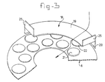
- Figure 3 shows a detail of the belt with guide plate according to the invention.
- the oven shown in the figures comprises a baseframe 1 over which a cover 2 is placed. Said cover 2 can be lifted relative to the baseframe 1 by means of known lifting means, which are not shown. Baseframe 1 and cover 2 are sealed with respect to one another by means of water lock 3.
- Two drums 4, 5 are arranged inside the oven.
- the conveyor belt which is indicated in its entirety by 8, is guided helically around the exterior of each drum 4, 5 by means of helical supports 6 arranged around the exterior of the drums.
- the drums can be driven by means of synchronised drive motors, connected to the shafts 7, which are supported in the baseframe 1.
- Boosters 9 which can be driven by means of motors 10 arranged outside the cover, are arranged in the cover. Said boosters draw in the air in accordance with the arrows shown in Figure 1 and force said air over the heating installation 11. During this operation the air is heated, and, via the heating installation 11, the air reaches the products which are located on the conveyor belt 8, likewise as shown in Figure 1.
- the duct through which the air flows from the boosters 9 to the associated heating installation 11 is indicated by 12. Said duct is delimited at the top by the cover 2 and at the bottom by plate 13, whilst the side boundary 14 of the ducts concerned can be seen in Figure 2.
- the discharge of the ducts downwards is indicated by 15; from the mouth 15, the air passes into a vertical tube which is delimited by the walls of the cover 2 and the windings.
- Jacket plates 16, 17 are mounted around the outside of each helically wound section of the belt 8. In the vicinity of the mouth of duct 12 the windings, which are located above one another, of the helical sections of the belt 8 are covered by a guide element, which is indicated in its entirety by 18, as is also shown in Figure 3.
- Each guide element 18 consists of a curved plate 19 which runs approximately parallel to the belt surface and a skirt 20.
- the hot air discharged through the mouth 15 flows over the plate 19 and then comes into contact with the products 21 located on the inside of the winding of the belt 8.
- Said products 21 are now supplied with hot air which has not yet been cooled down by the products 22 located further towards the outside.
- uniform heating of all products on the belt is ensured: this is because a situation is now prevented where the products 21 located on the inside are supplied with air which has already been cooled by the products 22 located on the outside.
- the products 21, 22 are heated in the same way over the remainder of the path of each winding, that is to say beyond the plates 18, such that no temperature differences between products located alongside one another on the belt occur over the path from the feed 23 to the discharge 24 from the conveyor belt 8.
- the guide elements can also be provided with upright baffles 25 located at the ends, which baffles make further advantageous guiding of the hot air possible.
Landscapes
- Life Sciences & Earth Sciences (AREA)
- Engineering & Computer Science (AREA)
- Food Science & Technology (AREA)
- Baking, Grill, Roasting (AREA)
- Drying Of Solid Materials (AREA)
- Cold Air Circulating Systems And Constructional Details In Refrigerators (AREA)
- Air Bags (AREA)
- Control And Other Processes For Unpacking Of Materials (AREA)
Claims (7)
- Ofen für die Zubereitung von Nahrungsprodukten, mit einem Gehäuse (1, 2), einem Förderband (8), das sich durch das Gehäuse hindurch bewegen läßt und auf dem die Nahrungsprodukte (21, 22) angeordnet werden können, wobei das Förderband (8) auf der Außenseite einer Trommel (4, 5) mit vertikaler Achse aufgenommen ist und einer schraubenlinienförmigen Bahn mit mehreren Windungen übereinander folgt, mit einer Heizeinrichtung (11) und einer Verstärkungseinrichtung (9, 10) zum Erzeugen eines Heißluftstromes durch einen Kanal in dem Gehäuse, wobei der Kanal eine Austrittsöffnung (15) für den Austritt der Heißluft in Verbindung mit der Erhitzung der auf dem Band (8) angeordneten Nahrungsprodukte (21, 22) aufweist,
dadurch gekennzeichnet, daß eine Platte (19) über sowie in etwa parallel zu einer Windung in einer derartigen Distanz angeordnet ist, daß die Produkte (21, 22) auf dem Band sich unter der Platte (19) hindurch weiterbewegen können, wobei die Platte (19) an dem Außenumfangsbereich des Bands (8) sowie in der Nähe der Austrittsöffnung des Kanals (12) angeordnet ist, um den Heißluftstrom in einer derartigen Weise über das Band (8) zu führen, daß die Produkte (21, 22) in Querrichtung des Bands (8) gleichmäßig erhitzt werden. - Ofen nach Anspruch 1,
mit einem Band, das mehrere Windungen übereinander aufweist, wobei eine zwischen zwei Windungen angeordnete Platte (19) in einer gewissen Distanz von der oberen Windung angeordnet ist, so daß ein Spalt für die Hindurchführung von Heißluft verbleibt. - Ofen nach Anspruch 1 oder 2,
wobei eine Zuführeinrichtung im Inneren des Gehäuses vorhanden ist, um die Heißluft von der Verstärkungseinrichtung (9, 10) auf die Außenseite der schraubenlinienförmigen Bahn zuzuführen, und wobei jede Platte (19) schmaler als das Band (18) ist und sich von außen her in Querrichtung des Bands erstreckt. - Ofen nach Anspruch 3,
wobei jede Platte (19) an der Außenseite eine Schürze (20) aufweist, die nach unten in Richtung auf das Band (8) gerichtet ist. - Ofen nach Anspruch 1, 2, 3 oder 4,
wobei jede Platte (19) an ihrem vorderen und/oder hinteren Ende eine nach oben gerichtete Barriere (25) aufweist. - Ofen nach Anspruch 2, 3, 4 oder 5,
wobei die Zuführeinrichtung eine Röhre bildet, die parallel zu der Achse der schraubenlinienförmigen Bahn verläuft und auf der der schraubenlinienförmigen Bahn zugewandten Seite offen ist, und wobei sich die Platten entlang der offenen Seite erstrecken. - Ofen nach Anspruch 6,
wobei der innerste Rand des Bands (8) auf der Außenseite einer Trommel (4, 5) mit einer vertikalen Achse aufgenommen ist und wobei der äußerste Rand des Bands (8) nach dem peripheren Bereich des Bands (8), wo sich die Platten (19) befinden, wenigstens zum Teil von einer entsprechend gekrümmten Mantelplatte (16, 17) umgeben ist.
Applications Claiming Priority (2)
| Application Number | Priority Date | Filing Date | Title |
|---|---|---|---|
| NL1003027 | 1996-05-03 | ||
| NL1003027A NL1003027C2 (nl) | 1996-05-03 | 1996-05-03 | Oven met hetelucht-geleiding. |
Publications (2)
| Publication Number | Publication Date |
|---|---|
| EP0804878A1 EP0804878A1 (de) | 1997-11-05 |
| EP0804878B1 true EP0804878B1 (de) | 2001-07-18 |
Family
ID=19762798
Family Applications (1)
| Application Number | Title | Priority Date | Filing Date |
|---|---|---|---|
| EP97201293A Expired - Lifetime EP0804878B1 (de) | 1996-05-03 | 1997-04-29 | Backofen mit Heissluftführung |
Country Status (7)
| Country | Link |
|---|---|
| US (1) | US5836240A (de) |
| EP (1) | EP0804878B1 (de) |
| AT (1) | ATE203142T1 (de) |
| DE (1) | DE69705668T2 (de) |
| DK (1) | DK0804878T3 (de) |
| ES (1) | ES2160888T3 (de) |
| NL (1) | NL1003027C2 (de) |
Families Citing this family (19)
| Publication number | Priority date | Publication date | Assignee | Title |
|---|---|---|---|---|
| NL1009020C2 (nl) | 1998-04-28 | 1999-10-29 | Stork Titan Bv | Behandelingsinrichting voor het met geconditioneerde lucht behandelen van voedselproducten. |
| NL1011199C1 (nl) * | 1998-04-28 | 1999-10-29 | Stork Titan Bv | Behandelingsinrichting voor het met geconditioneerde lucht behandelen van voedselproducten. |
| NL1012244C2 (nl) * | 1999-06-04 | 2000-12-06 | Koppens Bv | Spiraaloven met verbeterde bandaandrijving. |
| US6393348B1 (en) | 2000-07-14 | 2002-05-21 | Douglas K. Ziegler | Passenger monitoring vehicle safety seat and monitoring device |
| NL1017040C2 (nl) † | 2001-01-05 | 2002-07-08 | Koppens Bv | Oven met luchtstraalinrichting. |
| US7134543B2 (en) | 2004-09-22 | 2006-11-14 | Frito-Lay North America, Inc. | Containment apparatus for multi-pass ovens |
| NL1027446C2 (nl) * | 2004-11-08 | 2006-05-09 | Stork Titan Bv | Behandelingsinrichting en werkwijze voor het met geconditioneerde lucht behandelen van voedselproducten. |
| PL2987410T3 (pl) | 2008-06-19 | 2021-11-08 | Gea Food Solutions Bakel B.V. | Piec spiralny z kontrolowanym przepływem powietrza na szerokości taśmy |
| US8646383B1 (en) * | 2009-09-15 | 2014-02-11 | David Howard | Spiral oven apparatus and method of cooking |
| US20120204733A1 (en) * | 2011-02-15 | 2012-08-16 | Gilbert Dennis | Cooking System |
| US9107422B2 (en) | 2011-03-09 | 2015-08-18 | Unitherm Food Systems, Inc. | Airflow pattern for spiral ovens |
| US9220276B2 (en) * | 2011-03-09 | 2015-12-29 | Unitherm Food Systems, Inc. | Airflow pattern for spiral ovens |
| EP2532971A1 (de) * | 2011-06-07 | 2012-12-12 | Koninklijke Philips Electronics N.V. | Vorrichtung zur Lebensmittelzubereitung |
| US9161651B2 (en) * | 2012-01-27 | 2015-10-20 | Ts Techniek Bv | Dual drum spiral oven |
| US20170013991A1 (en) * | 2015-07-16 | 2017-01-19 | Unitherm Food Systems, Inc | Two-tier heat transfer system and method for its use |
| WO2017147473A1 (en) | 2016-02-26 | 2017-08-31 | Provisur Technologies, Inc. | Cooking devices and methods of using the same |
| NL2016385B1 (en) * | 2016-03-08 | 2017-09-27 | Marel Townsend Further Proc Bv | Closed processing system and method for treating elongated food products. |
| EP3451838A4 (de) | 2016-05-05 | 2020-04-01 | Provisur Technologies, Inc. | Spiralkochvorrichtungen und verfahren zur verwendung davon |
| CN115968919B (zh) * | 2023-03-02 | 2025-07-22 | 山东省食品药品检验研究院 | 一种低粘连油炸加工机 |
Family Cites Families (7)
| Publication number | Priority date | Publication date | Assignee | Title |
|---|---|---|---|---|
| FR1566750A (de) * | 1968-03-29 | 1969-05-09 | ||
| US4118181A (en) * | 1976-12-11 | 1978-10-03 | Hirosuke Onodera | Baking apparatus |
| AT383471B (de) * | 1984-08-08 | 1987-07-10 | Koenig Helmut | Backofen |
| US5078120A (en) * | 1990-01-26 | 1992-01-07 | Stein, Inc. | Cooking oven for slow cooking of food products |
| US5322007A (en) * | 1991-08-15 | 1994-06-21 | Heat And Control, Inc. | Compact, high-capacity oven |
| NL9200351A (nl) * | 1992-02-26 | 1993-09-16 | Koppens Maschf Bv | Oven. |
| US5702245A (en) * | 1996-03-20 | 1997-12-30 | Stein, Inc. | Conveyor for processing equipment having gas flow compensation |
-
1996
- 1996-05-03 NL NL1003027A patent/NL1003027C2/nl not_active IP Right Cessation
-
1997
- 1997-04-29 EP EP97201293A patent/EP0804878B1/de not_active Expired - Lifetime
- 1997-04-29 AT AT97201293T patent/ATE203142T1/de not_active IP Right Cessation
- 1997-04-29 DK DK97201293T patent/DK0804878T3/da active
- 1997-04-29 ES ES97201293T patent/ES2160888T3/es not_active Expired - Lifetime
- 1997-04-29 DE DE69705668T patent/DE69705668T2/de not_active Expired - Lifetime
- 1997-05-02 US US08/850,514 patent/US5836240A/en not_active Expired - Lifetime
Also Published As
| Publication number | Publication date |
|---|---|
| DK0804878T3 (da) | 2001-09-24 |
| ES2160888T3 (es) | 2001-11-16 |
| DE69705668T2 (de) | 2001-10-31 |
| US5836240A (en) | 1998-11-17 |
| NL1003027C2 (nl) | 1997-11-06 |
| DE69705668D1 (de) | 2001-08-23 |
| ATE203142T1 (de) | 2001-08-15 |
| EP0804878A1 (de) | 1997-11-05 |
Similar Documents
| Publication | Publication Date | Title |
|---|---|---|
| EP0804878B1 (de) | Backofen mit Heissluftführung | |
| CA2860529C (en) | Dual drum spiral oven | |
| EP0558151B1 (de) | Ofen | |
| EP1211914B1 (de) | Heizvorrichtung versehen mit einer Heizquelle unterschiedlicher von Mikrowellen bei einem Mikrowellenofen | |
| US4121509A (en) | Controlled atmosphere broiler | |
| US7290405B2 (en) | Method and apparatus for conducting heat to a glass sheet | |
| EP0870430B1 (de) | Dampfofen | |
| JPH1014504A (ja) | 製品を処理する処理装置、処理装置用のコンベヤ 及び製品の処理方法 | |
| KR930004695A (ko) | 처리증기를 사용하는 간편하고 고용량인 조리용 오븐 | |
| EP1221575B1 (de) | Ofen mit Flüssigstrahlvorrichtung | |
| US5156873A (en) | Multiple zone shrimp precooking method and apparatus for machine peeling shrimp | |
| CN113143053A (zh) | 烹饪设备 | |
| CN113143052A (zh) | 烹饪设备 | |
| US20100083525A1 (en) | Device and method for heat-treating a pourable plant product | |
| US2365769A (en) | Oven | |
| CN221060445U (zh) | 一种新型控温的电子式烤箱 | |
| JPS61295488A (ja) | 熱成形用の熱処理用熱可塑性シ−ト物質 | |
| SU1684578A1 (ru) | Установка дл микронизации зерна | |
| US5040974A (en) | Internal air circulation system for lanham oven | |
| US4246834A (en) | Patty broiler | |
| GB2147788A (en) | Biscuit manufacture | |
| CN220507610U (zh) | 一种多层式干燥机 | |
| CN216365947U (zh) | 一种中药炒药装置 | |
| EP0900353A1 (de) | Verfahren und vorrichtung zur trocknung von rieselfähigen feststoffpartikeln | |
| CN223415637U (zh) | 一种猫粮生产用挤压成型装置 |
Legal Events
| Date | Code | Title | Description |
|---|---|---|---|
| PUAI | Public reference made under article 153(3) epc to a published international application that has entered the european phase |
Free format text: ORIGINAL CODE: 0009012 |
|
| AK | Designated contracting states |
Kind code of ref document: A1 Designated state(s): AT BE CH DE DK ES FR GB IT LI NL SE |
|
| 17P | Request for examination filed |
Effective date: 19980316 |
|
| 17Q | First examination report despatched |
Effective date: 19991215 |
|
| GRAG | Despatch of communication of intention to grant |
Free format text: ORIGINAL CODE: EPIDOS AGRA |
|
| GRAG | Despatch of communication of intention to grant |
Free format text: ORIGINAL CODE: EPIDOS AGRA |
|
| GRAH | Despatch of communication of intention to grant a patent |
Free format text: ORIGINAL CODE: EPIDOS IGRA |
|
| GRAH | Despatch of communication of intention to grant a patent |
Free format text: ORIGINAL CODE: EPIDOS IGRA |
|
| GRAA | (expected) grant |
Free format text: ORIGINAL CODE: 0009210 |
|
| AK | Designated contracting states |
Kind code of ref document: B1 Designated state(s): AT BE CH DE DK ES FR GB IT LI NL SE |
|
| REF | Corresponds to: |
Ref document number: 203142 Country of ref document: AT Date of ref document: 20010815 Kind code of ref document: T |
|
| ITF | It: translation for a ep patent filed | ||
| REG | Reference to a national code |
Ref country code: CH Ref legal event code: EP |
|
| REG | Reference to a national code |
Ref country code: CH Ref legal event code: NV Representative=s name: BUGNION S.A. |
|
| REF | Corresponds to: |
Ref document number: 69705668 Country of ref document: DE Date of ref document: 20010823 |
|
| REG | Reference to a national code |
Ref country code: DK Ref legal event code: T3 |
|
| REG | Reference to a national code |
Ref country code: ES Ref legal event code: FG2A Ref document number: 2160888 Country of ref document: ES Kind code of ref document: T3 |
|
| ET | Fr: translation filed | ||
| REG | Reference to a national code |
Ref country code: GB Ref legal event code: IF02 |
|
| PLBE | No opposition filed within time limit |
Free format text: ORIGINAL CODE: 0009261 |
|
| STAA | Information on the status of an ep patent application or granted ep patent |
Free format text: STATUS: NO OPPOSITION FILED WITHIN TIME LIMIT |
|
| 26N | No opposition filed | ||
| PGFP | Annual fee paid to national office [announced via postgrant information from national office to epo] |
Ref country code: IT Payment date: 20060430 Year of fee payment: 10 |
|
| PGFP | Annual fee paid to national office [announced via postgrant information from national office to epo] |
Ref country code: BE Payment date: 20060523 Year of fee payment: 10 Ref country code: AT Payment date: 20060523 Year of fee payment: 10 |
|
| PGFP | Annual fee paid to national office [announced via postgrant information from national office to epo] |
Ref country code: SE Payment date: 20060524 Year of fee payment: 10 Ref country code: CH Payment date: 20060524 Year of fee payment: 10 |
|
| PGFP | Annual fee paid to national office [announced via postgrant information from national office to epo] |
Ref country code: ES Payment date: 20060526 Year of fee payment: 10 |
|
| PGFP | Annual fee paid to national office [announced via postgrant information from national office to epo] |
Ref country code: DK Payment date: 20070425 Year of fee payment: 11 |
|
| REG | Reference to a national code |
Ref country code: CH Ref legal event code: PL |
|
| BERE | Be: lapsed |
Owner name: *KOPPENS B.V. Effective date: 20070430 |
|
| PG25 | Lapsed in a contracting state [announced via postgrant information from national office to epo] |
Ref country code: CH Free format text: LAPSE BECAUSE OF NON-PAYMENT OF DUE FEES Effective date: 20070430 Ref country code: LI Free format text: LAPSE BECAUSE OF NON-PAYMENT OF DUE FEES Effective date: 20070430 Ref country code: AT Free format text: LAPSE BECAUSE OF NON-PAYMENT OF DUE FEES Effective date: 20070429 |
|
| PG25 | Lapsed in a contracting state [announced via postgrant information from national office to epo] |
Ref country code: BE Free format text: LAPSE BECAUSE OF NON-PAYMENT OF DUE FEES Effective date: 20070430 |
|
| PGFP | Annual fee paid to national office [announced via postgrant information from national office to epo] |
Ref country code: FR Payment date: 20070418 Year of fee payment: 11 |
|
| PG25 | Lapsed in a contracting state [announced via postgrant information from national office to epo] |
Ref country code: SE Free format text: LAPSE BECAUSE OF NON-PAYMENT OF DUE FEES Effective date: 20070430 |
|
| REG | Reference to a national code |
Ref country code: ES Ref legal event code: FD2A Effective date: 20070430 |
|
| PG25 | Lapsed in a contracting state [announced via postgrant information from national office to epo] |
Ref country code: ES Free format text: LAPSE BECAUSE OF NON-PAYMENT OF DUE FEES Effective date: 20070430 |
|
| REG | Reference to a national code |
Ref country code: DK Ref legal event code: EBP |
|
| PGFP | Annual fee paid to national office [announced via postgrant information from national office to epo] |
Ref country code: GB Payment date: 20080423 Year of fee payment: 12 |
|
| REG | Reference to a national code |
Ref country code: FR Ref legal event code: ST Effective date: 20081231 |
|
| PG25 | Lapsed in a contracting state [announced via postgrant information from national office to epo] |
Ref country code: FR Free format text: LAPSE BECAUSE OF NON-PAYMENT OF DUE FEES Effective date: 20080430 Ref country code: DK Free format text: LAPSE BECAUSE OF NON-PAYMENT OF DUE FEES Effective date: 20080430 |
|
| PG25 | Lapsed in a contracting state [announced via postgrant information from national office to epo] |
Ref country code: IT Free format text: LAPSE BECAUSE OF NON-PAYMENT OF DUE FEES Effective date: 20070429 |
|
| GBPC | Gb: european patent ceased through non-payment of renewal fee |
Effective date: 20090429 |
|
| PG25 | Lapsed in a contracting state [announced via postgrant information from national office to epo] |
Ref country code: GB Free format text: LAPSE BECAUSE OF NON-PAYMENT OF DUE FEES Effective date: 20090429 |
|
| PGFP | Annual fee paid to national office [announced via postgrant information from national office to epo] |
Ref country code: NL Payment date: 20160422 Year of fee payment: 20 |
|
| PGFP | Annual fee paid to national office [announced via postgrant information from national office to epo] |
Ref country code: DE Payment date: 20160421 Year of fee payment: 20 |
|
| REG | Reference to a national code |
Ref country code: DE Ref legal event code: R071 Ref document number: 69705668 Country of ref document: DE |
|
| REG | Reference to a national code |
Ref country code: NL Ref legal event code: MK Effective date: 20170428 |