EP0804388B1 - Systeme de goulottes pour transporter une goutte de verre d'un distributeur de verre a la preforme d'une machine a fabriquer le verre - Google Patents
Systeme de goulottes pour transporter une goutte de verre d'un distributeur de verre a la preforme d'une machine a fabriquer le verre Download PDFInfo
- Publication number
- EP0804388B1 EP0804388B1 EP96900900A EP96900900A EP0804388B1 EP 0804388 B1 EP0804388 B1 EP 0804388B1 EP 96900900 A EP96900900 A EP 96900900A EP 96900900 A EP96900900 A EP 96900900A EP 0804388 B1 EP0804388 B1 EP 0804388B1
- Authority
- EP
- European Patent Office
- Prior art keywords
- outlet
- chute
- glass
- channel
- drop
- Prior art date
- Legal status (The legal status is an assumption and is not a legal conclusion. Google has not performed a legal analysis and makes no representation as to the accuracy of the status listed.)
- Expired - Lifetime
Links
Images
Classifications
-
- C—CHEMISTRY; METALLURGY
- C03—GLASS; MINERAL OR SLAG WOOL
- C03B—MANUFACTURE, SHAPING, OR SUPPLEMENTARY PROCESSES
- C03B7/00—Distributors for the molten glass; Means for taking-off charges of molten glass; Producing the gob, e.g. controlling the gob shape, weight or delivery tact
- C03B7/14—Transferring molten glass or gobs to glass blowing or pressing machines
- C03B7/16—Transferring molten glass or gobs to glass blowing or pressing machines using deflector chutes
Definitions
- the invention relates to a channel arrangement for Transfer of a glass drop from a drop distributor to a preform of a glass machine, with a central channel, their inlet to a gutter of the drop distributor connected and the between their enema and its outlet is inclined downwards and a deflection channel, whose inlet is connected to the outlet of the central channel is, the outlet-side end portion approximately rectilinear is formed and by means of an adjustable suspension device so on a frame part of the glass machine is held that the position of their outlet on the central axis the preform of the glass machine is adaptable.
- the invention has for its object the generic Channel arrangement for transferring a glass drop from a drop distributor to a preform of a glass machine to develop such that an exactly centered Transfer of the glass drop from the deflection channel of the channel arrangement into the preform of the glass machine.
- This funnel-shaped outlet-side end section of the deflection channel is in arranged spatially fixed with respect to the preform.
- the remaining deflection channel is arranged to be movable. Because of their mobility becomes the central axis of the outlet area the deflection channel as far as possible in alignment with the central axis of the funnel or the preform. Slight deviations between the central axis of the outlet the deflection channel and the central axis of the funnel removed so far by the funnel effect that the glass drop exactly on the central axis of the funnel-shaped, to the preform spatially fixed end section leaves this.
- the glass drop gets exactly in the desired one Alignment in the preform. This results in a ideal distribution of the existing within the glass drop Glass material inside the preform. Furthermore, with the end portion designed according to the invention causes the glass drop is almost not deformed or is deformed as little as possible becomes.
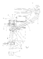
- a channel arrangement shown in Figure 1 is used for transfer a glass drop not shown in the figures from a drop distributor 1 of the glass machine into a preform 2 of the glass machine.
- FIG 1 there are two such Channel arrangements 3 shown, of which, since they are in terms of correspond to their function and their components, only one is described in detail.
- the drop distributor 1 For transferring the glass drop from the drop distributor 1 in the channel arrangement 3, the drop distributor 1 has a Collecting gutter 4.
- the gutter 4, which is curved in this way is that they are first in a vertical direction and then runs diagonally downwards, the channel arrangement 3 follows.
- the channel arrangement 3 has a central channel 5 and a deflection channel 6 on.
- the inlet of the central channel 5 is the outlet the gutter 4 of the drop distributor, the outlet the central channel 5 the inlet of the deflection channel 6 and the outlet the deflection channel 6 assigned to the inlet of the preform 2.
- the central channel 5 is approximately rectilinear and runs approximately in the same direction as the outlet side End section of the collecting trough 4 of the drop distributor 1.
- the central channel 5 is pivotable near its inlet a support arm firmly connected to the frame of the glass machine 7 stored. Because of the alignment the central channel 5 and the outlet end portion of the The gutter 4 of the drop distributor 1 is a uniform one and largely undisturbed transition of the glass drop from the Collecting channel 4 of the drop distributor 1 into the central channel 5 the channel arrangement 3 guaranteed.
- the outlet-side storage of the central channel 5 takes place by means of one between the outlet of the central channel 5 and the inlet the crossbar 6 arranged connecting crossbar 8.
- the connecting crossbar 8 is both with the outlet of the central channel 5 and the inlet of the deflection channel 6 connected.
- the connecting cross member 8 is shown in particular in FIG Ball head bearing 9 is provided. Whose bullet is there screwed to the free end of one on the connecting cross member 8 attached threaded bolt 10.
- Threaded bolt 10 on the connecting cross member 8 is the latter with a provided firmly on her mother 11.
- Connection crossbeam 8 is from a suspension device 13 held, which in turn via a joint 14 with one firmly connected to the frame of the glass machine Frame part 15 is connected.
- the joint 14 allows an adjustment of the inlet side End portion of the guide channel 6 in the arrow A indicated vertical direction, in the arrow B indicated horizontal direction and in the arrow C indicated, extending at right angles to the horizontal direction B. Horizontal direction C. So it is by means of the joint 14 possible to adjust the guide channel 6 so that the central axis 16 of its outlet largely with the central axis 17 the preform 2 is aligned.
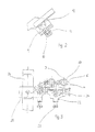
- the outlet-side end section 18 is spatially fixed in arranged with respect to the preform 2. It is therefore possible that the central axis 19 of the outlet-side end section 18th exactly aligned with the central axis 17 of the preform 2, so that a precisely centered transition of the not shown in the figures Glass drop from the outlet end section 18 in the preform 2 is possible.
- Compensate end section 18 is the outlet side End section 18 with a dashed line in the figure shown funnel 21 designed between the inlet of the outlet-side end section 18 and the Outlet tapered.
- This will in any case ensured that the remaining from the outlet 20 Deflection channel 6 in the outlet end section 18, the is separated from the deflection channel 6, transferred glass drops at the outlet of the outlet side provided with the funnel 21 End section 18 in exact alignment with the central axis 17 of the preform 2 of the glass machine moves.
- the outlet-side end section provided with the funnel 21 18 is held on a suspension unit 22, on the two Adjustment devices 23, 24 are provided, by means of which the position of the outlet-side end section 18 both in the direction D shown in Figure 3 as well as in the direction E shown in Figure 3 to the position the preform 2 of the glass machine can be adapted.
- the directions D and E are perpendicular to each other and to the vertically arranged Center axis 19 of the outlet-side end section 18th
- the suspension unit 22 of the outlet-side end section 18 in turn is connected to a carriage 25 which is on a rail 26 is movable. This makes it comparative less expensive, the outlet-side end section 18th to be replaced by another, for example better is adapted to a preform also exchanged.
Landscapes
- Chemical & Material Sciences (AREA)
- Engineering & Computer Science (AREA)
- Materials Engineering (AREA)
- Organic Chemistry (AREA)
- Branching, Merging, And Special Transfer Between Conveyors (AREA)
- Processing And Handling Of Plastics And Other Materials For Molding In General (AREA)
- Feeding Of Articles To Conveyors (AREA)
- Automobile Manufacture Line, Endless Track Vehicle, Trailer (AREA)
- Re-Forming, After-Treatment, Cutting And Transporting Of Glass Products (AREA)
Claims (5)
- Agencement de goulotte pour amener une goutte de verre d'un répartiteur de gouttes (1) à une préforme (2) d'une machine de travail du verre comportant une goulotte intermédiaire (5) dont l'entrée est connectée à une goulotte de sortie (4) du répartiteur de gouttes (1) et qui est inclinée vers le bas entre son entrée et sa sortie, une goulotte de déviation (6) dont l'entrée est connectée à la sortie de la goulotte intermédiaire et dont le tronçon d'extrémité (18) côté sortie est sensiblement rectiligne et qui est fixée à l'aide d'un dispositif de suspension réglable (13) à un élément de cadre (15) de la machine de travail du verre de telle sorte que la position de sa sortie puisse être adaptée par rapport à l'axe médian (17) de la préforme (2) de la machine de travail du verre, caractérisé par le fait que le tronçon d'extrémité (18) côté sortie de la goulotte de déviation (6) est séparé de cette dernière et est agencé en forme d'entonnoir (21).
- Agencement de goulotte selon la revendication 1, dans lequel le tronçon d'extrémité (18) côté sortie de la goulotte de déviation (6) est tenu à l'aide d'une unité de suspension (22) et est réglable suivant deux axes (D; E) mutuellement perpendiculaires et perpendiculaires à l'axe médian (19) du tronçon d'extrémité (18) grâce à deux dispositifs de réglage (23, 24) prévus sur l'unité de suspension (22).
- Agencement de goulotte selon la revendication 1 ou 2, dans lequel l'unité de suspension (22) est disposée sur un chariot (25) qui se déplace sur un rail (26).
- Agencement de goulotte selon une des revendications 1 à 3, dans lequel la sortie de la goulotte intermédiaire (5) et l'entrée de la goulotte de déviation (6) sont reliées l'une à l'autre à l'aide d'une traverse de liaison (8) entre laquelle et la sortie de la goulotte intermédiaire (5) est disposé un palier sphérique (9).
- Agencement de goulotte selon une des revendications 1 à 4, dans lequel le dispositif de suspension (13) de la goulotte de déviation (6) à est lié à l'élément de cadre (15) de la machine de travail du verre à l'aide d'une articulation (14) réglable suivants trois axes mutuellement perpendiculaires.
Applications Claiming Priority (3)
| Application Number | Priority Date | Filing Date | Title |
|---|---|---|---|
| DE19501762 | 1995-01-21 | ||
| DE19501762A DE19501762C2 (de) | 1995-01-21 | 1995-01-21 | Rinnenanordnung zur Überführung eines Glastropfens von einem Tropfenverteiler zu einer Vorform einer Glasmaschine |
| PCT/EP1996/000017 WO1996022253A1 (fr) | 1995-01-21 | 1996-01-04 | Systeme de goulottes pour transporter une goutte de verre d'un distributeur de verre a la preforme d'une machine a fabriquer le verre |
Publications (2)
| Publication Number | Publication Date |
|---|---|
| EP0804388A1 EP0804388A1 (fr) | 1997-11-05 |
| EP0804388B1 true EP0804388B1 (fr) | 1998-11-11 |
Family
ID=7751997
Family Applications (1)
| Application Number | Title | Priority Date | Filing Date |
|---|---|---|---|
| EP96900900A Expired - Lifetime EP0804388B1 (fr) | 1995-01-21 | 1996-01-04 | Systeme de goulottes pour transporter une goutte de verre d'un distributeur de verre a la preforme d'une machine a fabriquer le verre |
Country Status (5)
| Country | Link |
|---|---|
| US (1) | US5888267A (fr) |
| EP (1) | EP0804388B1 (fr) |
| JP (1) | JP3970320B2 (fr) |
| DE (2) | DE19501762C2 (fr) |
| WO (1) | WO1996022253A1 (fr) |
Families Citing this family (8)
| Publication number | Priority date | Publication date | Assignee | Title |
|---|---|---|---|---|
| IT245774Y1 (it) * | 1998-01-13 | 2002-03-26 | Bottero Spa | Gruppo di consegna goccia per una macchina di formatura di articoli divetro. |
| ITTO980022A1 (it) * | 1998-01-13 | 1999-07-13 | Bottero Spa | Gruppo di consegna per il convogliamento di gocce di vetro verso uno s tampo di una macchina per la formatura di articoli di vetro. |
| US6032492A (en) * | 1998-12-03 | 2000-03-07 | Emhart Glass S.A. | I.S. machine |
| US6170295B1 (en) * | 1999-03-04 | 2001-01-09 | Emhart Glass S.A. | I.S. machine |
| US6776011B2 (en) * | 2000-08-21 | 2004-08-17 | Owens-Brockway Glass Container Inc. | Apparatus for conveying gobs of glass to a glass container forming machine |
| US7543461B2 (en) * | 2004-10-12 | 2009-06-09 | Owens-Brockway Glass Container Inc. | Variable radius deflector |
| CN105110606B (zh) * | 2015-09-24 | 2017-06-16 | 山东三金玻璃机械有限公司 | 一种独立调整的行列式制瓶机流料槽支架 |
| DE202016004390U1 (de) * | 2016-07-19 | 2017-10-20 | Rolf Themann & Partner SA | Rinnenanlage zum Transport von Glastropfen von einer Speiservorrichtung zu Stationen einer Glasmaschine |
Family Cites Families (17)
| Publication number | Priority date | Publication date | Assignee | Title |
|---|---|---|---|---|
| FR554674A (fr) * | 1923-06-15 | |||
| US1653479A (en) * | 1927-12-20 | soubier | ||
| US1331511A (en) * | 1918-06-17 | 1920-02-24 | Owens Bottle Machine Company | Apparatus for transferring glass to molds |
| US1331536A (en) * | 1918-07-08 | 1920-02-24 | Owens Bottle Machine Company | Means for transferring molten glass to molds |
| US1692553A (en) * | 1921-09-23 | 1928-11-20 | Owens Bottle Co | Glass-feeding mechanism |
| US1645221A (en) * | 1926-11-20 | 1927-10-11 | Hartford Empire Co | Method and apparatus for feeding molten glass |
| US2147307A (en) * | 1936-06-20 | 1939-02-14 | Capstan Glass Co | Charge forming machine |
| US2293860A (en) * | 1940-03-08 | 1942-08-25 | Jeannette Glass Company | Method of feeding glass |
| US2334064A (en) * | 1940-05-01 | 1943-11-09 | Gen Electric | Glass feeding apparatus |
| US2758421A (en) * | 1952-04-03 | 1956-08-14 | Owens Illinois Glass Co | Chute for conveying molten glass |
| US2873555A (en) * | 1954-01-27 | 1959-02-17 | Owens Illinois Glass Co | Chute for conveying molten glass |
| US3198617A (en) * | 1959-10-08 | 1965-08-03 | Owens Illinois Glass Co | Mechanism for pressing charges of molten glass in a forming mold |
| US3198616A (en) * | 1960-12-09 | 1965-08-03 | Owens Illinois Glass Co | Apparatus for conveying molten glass charges |
| FR2193792A1 (en) * | 1973-07-24 | 1974-02-22 | Emhart Corp | Automatic control of weight of glass articles - using tiltable tube allo-wing for variations in viscosity |
| JP2535360B2 (ja) * | 1987-11-18 | 1996-09-18 | 株式会社ナべヤ | ゴブ案内装置 |
| GB2249089B (en) * | 1990-10-10 | 1994-03-30 | Vhc Ltd | Improved alignment apparatus |
| DE4116593C1 (fr) * | 1991-05-22 | 1993-01-07 | Fa. Hermann Heye, 3063 Obernkirchen, De |
-
1995
- 1995-01-21 DE DE19501762A patent/DE19501762C2/de not_active Expired - Fee Related
-
1996
- 1996-01-04 US US08/894,218 patent/US5888267A/en not_active Expired - Lifetime
- 1996-01-04 WO PCT/EP1996/000017 patent/WO1996022253A1/fr not_active Ceased
- 1996-01-04 DE DE59600806T patent/DE59600806D1/de not_active Expired - Lifetime
- 1996-01-04 JP JP52199496A patent/JP3970320B2/ja not_active Expired - Lifetime
- 1996-01-04 EP EP96900900A patent/EP0804388B1/fr not_active Expired - Lifetime
Also Published As
| Publication number | Publication date |
|---|---|
| JP3970320B2 (ja) | 2007-09-05 |
| DE19501762A1 (de) | 1996-07-25 |
| DE19501762C2 (de) | 1997-04-30 |
| US5888267A (en) | 1999-03-30 |
| EP0804388A1 (fr) | 1997-11-05 |
| WO1996022253A1 (fr) | 1996-07-25 |
| DE59600806D1 (de) | 1998-12-17 |
| JPH10512230A (ja) | 1998-11-24 |
Similar Documents
| Publication | Publication Date | Title |
|---|---|---|
| DE19535930C1 (de) | Vorrichtung zur veränderlichen Begrenzung eines flachen Fließkanals und Verfahren zum Austragen einer Massebahn mit veränderlicher Geometrie | |
| EP0654451B1 (fr) | Goulotte d'écoulement pour une machine de fabrication d'objets en verre | |
| EP0382135B1 (fr) | Elément d'enraînement pour lève-glace à câble | |
| DE3878650T2 (de) | Regelvorrichtung fuer mehrfache tropfenspeiser zum schneiden in einer geraden linie. | |
| EP0804388B1 (fr) | Systeme de goulottes pour transporter une goutte de verre d'un distributeur de verre a la preforme d'une machine a fabriquer le verre | |
| DE69105452T2 (de) | Verbesserte Ausgleichvorrichtung. | |
| CH711070B1 (de) | Pneumatisches Verstellsystem. | |
| DE60302471T2 (de) | Ausrichtungsmittel für eine spritzgiessvorrichtung | |
| WO1996026824A1 (fr) | Dispositif de demoulage de pieces coulees | |
| EP0787110B1 (fr) | Structure de conduits pour machine a mouler le verre a section individuelle | |
| EP0898155B1 (fr) | Assemblage d'alimentation pour décharger un matériau coulant dans un dispositif de dosage | |
| DE1956889A1 (de) | Vorrichtung zur Korrektur der Durchbiegung eines horizontalen Halterungselementes einer Werkzeugmaschine | |
| DE10328104B4 (de) | Extrusionsdüse mit zumindest einem flexiblen Lippenelement | |
| DE202004021625U1 (de) | Schnellrüstsystem für Kalibriervorrichtungen | |
| DE3541256A1 (de) | Pantograph | |
| DE69203323T2 (de) | Vorrichtung zum kontinuierlichen filtrieren. | |
| EP0728544A1 (fr) | Dispositif permettant de transférer des pièces dans une série de postes de travail | |
| DE69210573T2 (de) | Abschneidescherenmechanismus für eine Glasformmaschine | |
| DE3024311A1 (de) | Beschickungseinrichtung fuer kokillengussmaschine | |
| DE4200628C1 (en) | Extruder head with e.g. three settings - has die and intermediate feed tool which can both be rotated to align their angled flow bores differently with that supplied from extruder | |
| DE69822116T2 (de) | Vorrichtung zur Speisung von Glasposten in eine Maschine zur Herstellung von Glasgegenständen | |
| DE4004282C1 (en) | Appts. for plastic pipe prodn. - comprises injection head with nozzle unit and moulding unit having two matrix sections | |
| EP0761852A1 (fr) | Banc d'étirage avec appareil de reglage de l'écartement des rouleaux d'étirage | |
| DE1806204C3 (de) | Niederdruck-Gießvorrichtung | |
| EP0769358A2 (fr) | Procédé et installation pour insérer un boudin de matériau dans un moule |
Legal Events
| Date | Code | Title | Description |
|---|---|---|---|
| PUAI | Public reference made under article 153(3) epc to a published international application that has entered the european phase |
Free format text: ORIGINAL CODE: 0009012 |
|
| 17P | Request for examination filed |
Effective date: 19970703 |
|
| AK | Designated contracting states |
Kind code of ref document: A1 Designated state(s): CH DE FR GB IT LI SE |
|
| GRAG | Despatch of communication of intention to grant |
Free format text: ORIGINAL CODE: EPIDOS AGRA |
|
| 17Q | First examination report despatched |
Effective date: 19980113 |
|
| GRAG | Despatch of communication of intention to grant |
Free format text: ORIGINAL CODE: EPIDOS AGRA |
|
| GRAH | Despatch of communication of intention to grant a patent |
Free format text: ORIGINAL CODE: EPIDOS IGRA |
|
| GRAH | Despatch of communication of intention to grant a patent |
Free format text: ORIGINAL CODE: EPIDOS IGRA |
|
| GRAA | (expected) grant |
Free format text: ORIGINAL CODE: 0009210 |
|
| AK | Designated contracting states |
Kind code of ref document: B1 Designated state(s): CH DE FR GB IT LI SE |
|
| REG | Reference to a national code |
Ref country code: CH Ref legal event code: EP |
|
| REF | Corresponds to: |
Ref document number: 59600806 Country of ref document: DE Date of ref document: 19981217 |
|
| ITF | It: translation for a ep patent filed | ||
| ET | Fr: translation filed | ||
| GBT | Gb: translation of ep patent filed (gb section 77(6)(a)/1977) |
Effective date: 19990209 |
|
| PLBE | No opposition filed within time limit |
Free format text: ORIGINAL CODE: 0009261 |
|
| STAA | Information on the status of an ep patent application or granted ep patent |
Free format text: STATUS: NO OPPOSITION FILED WITHIN TIME LIMIT |
|
| 26N | No opposition filed | ||
| PG25 | Lapsed in a contracting state [announced via postgrant information from national office to epo] |
Ref country code: LI Free format text: LAPSE BECAUSE OF NON-PAYMENT OF DUE FEES Effective date: 20000131 Ref country code: CH Free format text: LAPSE BECAUSE OF NON-PAYMENT OF DUE FEES Effective date: 20000131 |
|
| REG | Reference to a national code |
Ref country code: CH Ref legal event code: PL |
|
| REG | Reference to a national code |
Ref country code: GB Ref legal event code: IF02 |
|
| PGFP | Annual fee paid to national office [announced via postgrant information from national office to epo] |
Ref country code: FR Payment date: 20090120 Year of fee payment: 14 |
|
| REG | Reference to a national code |
Ref country code: FR Ref legal event code: ST Effective date: 20100930 |
|
| PG25 | Lapsed in a contracting state [announced via postgrant information from national office to epo] |
Ref country code: FR Free format text: LAPSE BECAUSE OF NON-PAYMENT OF DUE FEES Effective date: 20100201 |
|
| PGFP | Annual fee paid to national office [announced via postgrant information from national office to epo] |
Ref country code: IT Payment date: 20110126 Year of fee payment: 16 Ref country code: SE Payment date: 20110121 Year of fee payment: 16 Ref country code: DE Payment date: 20110318 Year of fee payment: 16 |
|
| PGFP | Annual fee paid to national office [announced via postgrant information from national office to epo] |
Ref country code: GB Payment date: 20110121 Year of fee payment: 16 |
|
| REG | Reference to a national code |
Ref country code: SE Ref legal event code: EUG |
|
| GBPC | Gb: european patent ceased through non-payment of renewal fee |
Effective date: 20120104 |
|
| PG25 | Lapsed in a contracting state [announced via postgrant information from national office to epo] |
Ref country code: SE Free format text: LAPSE BECAUSE OF NON-PAYMENT OF DUE FEES Effective date: 20120105 Ref country code: GB Free format text: LAPSE BECAUSE OF NON-PAYMENT OF DUE FEES Effective date: 20120104 Ref country code: DE Free format text: LAPSE BECAUSE OF NON-PAYMENT OF DUE FEES Effective date: 20120801 |
|
| REG | Reference to a national code |
Ref country code: DE Ref legal event code: R119 Ref document number: 59600806 Country of ref document: DE Effective date: 20120801 |
|
| PG25 | Lapsed in a contracting state [announced via postgrant information from national office to epo] |
Ref country code: IT Free format text: LAPSE BECAUSE OF NON-PAYMENT OF DUE FEES Effective date: 20120104 |