EP0804388B1 - Channel arrangement for transferring a drop of glass from a drop distributor to a pre-mould of a glass machine - Google Patents
Channel arrangement for transferring a drop of glass from a drop distributor to a pre-mould of a glass machine Download PDFInfo
- Publication number
- EP0804388B1 EP0804388B1 EP96900900A EP96900900A EP0804388B1 EP 0804388 B1 EP0804388 B1 EP 0804388B1 EP 96900900 A EP96900900 A EP 96900900A EP 96900900 A EP96900900 A EP 96900900A EP 0804388 B1 EP0804388 B1 EP 0804388B1
- Authority
- EP
- European Patent Office
- Prior art keywords
- outlet
- chute
- glass
- channel
- drop
- Prior art date
- Legal status (The legal status is an assumption and is not a legal conclusion. Google has not performed a legal analysis and makes no representation as to the accuracy of the status listed.)
- Expired - Lifetime
Links
Images
Classifications
-
- C—CHEMISTRY; METALLURGY
- C03—GLASS; MINERAL OR SLAG WOOL
- C03B—MANUFACTURE, SHAPING, OR SUPPLEMENTARY PROCESSES
- C03B7/00—Distributors for the molten glass; Means for taking-off charges of molten glass; Producing the gob, e.g. controlling the gob shape, weight or delivery tact
- C03B7/14—Transferring molten glass or gobs to glass blowing or pressing machines
- C03B7/16—Transferring molten glass or gobs to glass blowing or pressing machines using deflector chutes
Definitions
- the invention relates to a channel arrangement for Transfer of a glass drop from a drop distributor to a preform of a glass machine, with a central channel, their inlet to a gutter of the drop distributor connected and the between their enema and its outlet is inclined downwards and a deflection channel, whose inlet is connected to the outlet of the central channel is, the outlet-side end portion approximately rectilinear is formed and by means of an adjustable suspension device so on a frame part of the glass machine is held that the position of their outlet on the central axis the preform of the glass machine is adaptable.
- the invention has for its object the generic Channel arrangement for transferring a glass drop from a drop distributor to a preform of a glass machine to develop such that an exactly centered Transfer of the glass drop from the deflection channel of the channel arrangement into the preform of the glass machine.
- This funnel-shaped outlet-side end section of the deflection channel is in arranged spatially fixed with respect to the preform.
- the remaining deflection channel is arranged to be movable. Because of their mobility becomes the central axis of the outlet area the deflection channel as far as possible in alignment with the central axis of the funnel or the preform. Slight deviations between the central axis of the outlet the deflection channel and the central axis of the funnel removed so far by the funnel effect that the glass drop exactly on the central axis of the funnel-shaped, to the preform spatially fixed end section leaves this.
- the glass drop gets exactly in the desired one Alignment in the preform. This results in a ideal distribution of the existing within the glass drop Glass material inside the preform. Furthermore, with the end portion designed according to the invention causes the glass drop is almost not deformed or is deformed as little as possible becomes.
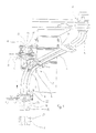
- a channel arrangement shown in Figure 1 is used for transfer a glass drop not shown in the figures from a drop distributor 1 of the glass machine into a preform 2 of the glass machine.
- FIG 1 there are two such Channel arrangements 3 shown, of which, since they are in terms of correspond to their function and their components, only one is described in detail.
- the drop distributor 1 For transferring the glass drop from the drop distributor 1 in the channel arrangement 3, the drop distributor 1 has a Collecting gutter 4.
- the gutter 4, which is curved in this way is that they are first in a vertical direction and then runs diagonally downwards, the channel arrangement 3 follows.
- the channel arrangement 3 has a central channel 5 and a deflection channel 6 on.
- the inlet of the central channel 5 is the outlet the gutter 4 of the drop distributor, the outlet the central channel 5 the inlet of the deflection channel 6 and the outlet the deflection channel 6 assigned to the inlet of the preform 2.
- the central channel 5 is approximately rectilinear and runs approximately in the same direction as the outlet side End section of the collecting trough 4 of the drop distributor 1.
- the central channel 5 is pivotable near its inlet a support arm firmly connected to the frame of the glass machine 7 stored. Because of the alignment the central channel 5 and the outlet end portion of the The gutter 4 of the drop distributor 1 is a uniform one and largely undisturbed transition of the glass drop from the Collecting channel 4 of the drop distributor 1 into the central channel 5 the channel arrangement 3 guaranteed.
- the outlet-side storage of the central channel 5 takes place by means of one between the outlet of the central channel 5 and the inlet the crossbar 6 arranged connecting crossbar 8.
- the connecting crossbar 8 is both with the outlet of the central channel 5 and the inlet of the deflection channel 6 connected.
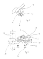
- the connecting cross member 8 is shown in particular in FIG Ball head bearing 9 is provided. Whose bullet is there screwed to the free end of one on the connecting cross member 8 attached threaded bolt 10.
- Threaded bolt 10 on the connecting cross member 8 is the latter with a provided firmly on her mother 11.
- Connection crossbeam 8 is from a suspension device 13 held, which in turn via a joint 14 with one firmly connected to the frame of the glass machine Frame part 15 is connected.
- the joint 14 allows an adjustment of the inlet side End portion of the guide channel 6 in the arrow A indicated vertical direction, in the arrow B indicated horizontal direction and in the arrow C indicated, extending at right angles to the horizontal direction B. Horizontal direction C. So it is by means of the joint 14 possible to adjust the guide channel 6 so that the central axis 16 of its outlet largely with the central axis 17 the preform 2 is aligned.
- the outlet-side end section 18 is spatially fixed in arranged with respect to the preform 2. It is therefore possible that the central axis 19 of the outlet-side end section 18th exactly aligned with the central axis 17 of the preform 2, so that a precisely centered transition of the not shown in the figures Glass drop from the outlet end section 18 in the preform 2 is possible.
- Compensate end section 18 is the outlet side End section 18 with a dashed line in the figure shown funnel 21 designed between the inlet of the outlet-side end section 18 and the Outlet tapered.
- This will in any case ensured that the remaining from the outlet 20 Deflection channel 6 in the outlet end section 18, the is separated from the deflection channel 6, transferred glass drops at the outlet of the outlet side provided with the funnel 21 End section 18 in exact alignment with the central axis 17 of the preform 2 of the glass machine moves.
- the outlet-side end section provided with the funnel 21 18 is held on a suspension unit 22, on the two Adjustment devices 23, 24 are provided, by means of which the position of the outlet-side end section 18 both in the direction D shown in Figure 3 as well as in the direction E shown in Figure 3 to the position the preform 2 of the glass machine can be adapted.
- the directions D and E are perpendicular to each other and to the vertically arranged Center axis 19 of the outlet-side end section 18th
- the suspension unit 22 of the outlet-side end section 18 in turn is connected to a carriage 25 which is on a rail 26 is movable. This makes it comparative less expensive, the outlet-side end section 18th to be replaced by another, for example better is adapted to a preform also exchanged.
Landscapes
- Chemical & Material Sciences (AREA)
- Engineering & Computer Science (AREA)
- Materials Engineering (AREA)
- Organic Chemistry (AREA)
- Branching, Merging, And Special Transfer Between Conveyors (AREA)
- Processing And Handling Of Plastics And Other Materials For Molding In General (AREA)
- Feeding Of Articles To Conveyors (AREA)
- Automobile Manufacture Line, Endless Track Vehicle, Trailer (AREA)
- Re-Forming, After-Treatment, Cutting And Transporting Of Glass Products (AREA)
Description
Die Erfindung bezieht sich auf eine Rinnenanordnung zur Überführung eines Glastropfens von einem Tropfenverteiler zu einer Vorform einer Glasmaschine, mit einer Mittelrinne, deren Einlauf an eine Auffangrinne des Tropfenverteilers angeschlossen und die zwischen ihrem Einlauf und ihrem Auslauf abwärts geneigt ist, und einer Umlenkrinne, deren Einlauf an den Auslauf der Mittelrinne angeschlossen ist, deren auslaufseitiger Endabschnitt etwa geradlinig ausgebildet ist und die mittels einer verstellbaren Aufhängevorrichtung so an einem Rahmenteil der Glasmaschine gehaltert ist, daß die Position ihres Auslaufs an die Mittelachse der Vorform der Glasmaschine anpaßbar ist.The invention relates to a channel arrangement for Transfer of a glass drop from a drop distributor to a preform of a glass machine, with a central channel, their inlet to a gutter of the drop distributor connected and the between their enema and its outlet is inclined downwards and a deflection channel, whose inlet is connected to the outlet of the central channel is, the outlet-side end portion approximately rectilinear is formed and by means of an adjustable suspension device so on a frame part of the glass machine is held that the position of their outlet on the central axis the preform of the glass machine is adaptable.
Bei bekannten derartigen Rinnenanordnungen wird eine möglichst störungsfreie Übergabe des Glastropfens aus der Umlenkrinne in die Vorform dadurch zu erreichen versucht, daß der Auslauf der Umlenkrinne mit letzterer bewegbar ist, so daß er in Fluchtung mit der Mittelachse der Vorform gebracht werten kann. Aufgrund der Beweglichkeit der Umlenkrinne in bezug auf die Vorform kommt es jedoch zu leichten Abweichungen zwischen der Mittelachse des auslaufseitigen Endabschnitts der Umlenkrinne und der Mittelachse der Vorform. Hieraus resultieren Qualitätseinbußen bei dem aus dem Glastropfen hergestellten Glasartikel.In known channel arrangements of this type, one is possible trouble-free transfer of the glass drop from the deflection channel in the preform trying to achieve that the outlet of the deflection channel is movable with the latter, so that he is aligned with the central axis of the preform can evaluate. Due to the flexibility of the deflection channel however, with regard to the preform, it is easy Deviations between the center axis of the outlet side End section of the deflection channel and the central axis of the preform. This results in loss of quality in the from Glass drops made glass items.
Der Erfindung liegt die Aufgabe zugrunde, die gattungsgemäße Rinnenanordnung zur Überführung eines Glastropfens von einem Tropfenverteiler zu einer Vorform einer Glasmaschine derart weiterzubilden, daß eine exakt zentrierte Übergabe des Glastropfens aus der Umlenkrinne der Rinnenanordnung in die Vorform der Glasmaschine ermöglicht wird.The invention has for its object the generic Channel arrangement for transferring a glass drop from a drop distributor to a preform of a glass machine to develop such that an exactly centered Transfer of the glass drop from the deflection channel of the channel arrangement into the preform of the glass machine.
Diese Aufgabe wird erfindungsgemäß dadurch gelöst, daß der auslaufseitige Endabschnitt der Umlenkrinne von dieser abgetrennt und als Trichter ausgebildet ist. Dieser trichterförmige auslaufseitige Endabschnitt der Umlenkrinne ist in bezug auf die Vorform räumlich fixiert angeordnet. Zum Trichter, der sich in Richtung auf die Vorform verjüngt, beweglich ist die verbleibende Umlenkrinne angeordnet. Aufgrund ihrer Beweglichkeit wird die Mittelachse des Auslaufbereichs der Umlenkrinne möglichst weit in Fluchtung mit der Mittelachse des Trichters bzw. der Vorform gestellt. Leichte Abweichungen zwischen der Mittelachse des Auslaufs der Umlenkrinne und der Mittelachse des Trichters werden durch die Trichterwirkung soweit beseitigt, daß der Glastropfen exakt auf der Mittelachse des trichterförmigen, zur Vorform räumlich fixierten Endabschnitts diesen verläßt. Da dessen Mittelachse aufgrund seiner zur Vorform fixierten räumlichen Anordnung immer mit der Mittelachse der Vorform fluchtet, gerät der Glastropfen exakt in der gewünschten Ausrichtung in die Vorform. Hierdurch ergibt sich eine ideale Verteilung des innerhalb des Glastropfens vorhandenen Glasmaterials innerhalb der Vorform. Des weiteren wird mit dem erfindungsgemäß ausgebildeten Endabschnitt bewirkt, daß der Glastropfen nahezu nicht bzw. möglichst geringfügig verformt wird.This object is achieved in that the end section of the deflection channel separated from the latter and is designed as a funnel. This funnel-shaped outlet-side end section of the deflection channel is in arranged spatially fixed with respect to the preform. To the Funnel that tapers towards the preform the remaining deflection channel is arranged to be movable. Because of their mobility becomes the central axis of the outlet area the deflection channel as far as possible in alignment with the central axis of the funnel or the preform. Slight deviations between the central axis of the outlet the deflection channel and the central axis of the funnel removed so far by the funnel effect that the glass drop exactly on the central axis of the funnel-shaped, to the preform spatially fixed end section leaves this. Because its central axis due to its fixed to the preform spatial arrangement always with the central axis of the preform aligned, the glass drop gets exactly in the desired one Alignment in the preform. This results in a ideal distribution of the existing within the glass drop Glass material inside the preform. Furthermore, with the end portion designed according to the invention causes the glass drop is almost not deformed or is deformed as little as possible becomes.
Eine exakte Ausrichtung der Mittelachse des trichterförmigen, separaten auslaufseitigen Endabschnitts der Umlenkrinne mit der Mittelachse der Vorform wird in einfacher Weise möglich, wenn der auslaufseitige Endabschnitt der Umlenkrinne mittels einer Aufhängeeinheit gehaltert und mittels zweier an der Aufhängeeinheit vorgesehener Verstelleinrichtung in zwei zueinander und zur Mittelachse des Endabschnitts senkrechten Achse verstellbar ist.An exact alignment of the central axis of the funnel-shaped, separate outlet-side end section of the deflection channel with the central axis of the preform is easily possible if the outlet-side end section of the deflection channel by means of a suspension unit and by means of two on the suspension unit provided adjustment device in two to each other and perpendicular to the central axis of the end portion Axis is adjustable.
Zum Austausch der separaten auslaufseitigen Endabschnitte ist es zweckmäßig, wenn die vorstehend erwähnte Aufhängeeinheit an einem Schlitten angeordnet ist, der auf einer Schiene verfahrbar ist. Hierdurch wird beispielsweise eine Auswechselung der trichterförmigen, auslaufseitigen Endabschnitte der Umlenkrinne ermöglicht.To replace the separate outlet end sections it is useful if the above-mentioned suspension unit is arranged on a carriage which is on a Rail is movable. This will, for example Replacement of the funnel-shaped, outlet-side end sections the deflection channel enables.
Ein möglichst wenig störanfälliger und wenig die Qualität des Glastropfens beeinträchtigender Übergang zwischen der Mittelrinne der Rinnenanordnung und deren Umlenkrinne ist möglich, wenn der Auslauf der Mittelrinne und der Einlauf der Umlenkrinne mittels einer Verbindungstraverse miteinander verbunden sind, zwischen der und dem Auslauf der Mittelrinne ein Kugelkopflager angeordnet ist. Hierdurch ergibt sich bei jedweder Bewegung der Umlenkrinne eine entsprechende Anpassung des Auslaufs der Mittelrinne, wodurch ein störungsfreier Übergang des Glastropfens aus dem Auslauf der Mittelrinne in den Einlauf der Umlenkrinne gewährleistet wird.The least possible failure and the quality of the glass drop impairing transition between the Middle channel of the channel arrangement and its deflection channel is possible if the outlet of the central channel and the inlet the deflection channel by means of a connecting cross are connected between the and the outlet of the central channel a ball head bearing is arranged. This gives with each movement of the deflection channel Adjustment of the spout of the central channel, whereby a trouble-free transition of the glass drop from the spout the central channel is guaranteed in the inlet of the deflection channel becomes.
Eine möglichst genaue Ausrichtung der Mittelachse des auslaufseitigen Endbereichs der verbliebenen Umlenkrinne ist erzielbar, wenn die Aufhängevorrichtung der Umlenkrinne mittels eines in drei zueinander rechtwinkligen Achsen verstellbaren Gelenks mit dem Rahmenteil der Glasmaschine verbunden ist. Hierdurch kann die Beanspruchung des Glastropfens im auf die verbliebene Umlenkrinne folgenden, in bezug auf die Vorform räumlich fixierten trichterförmigen Endabschnitt weiter verringert werden.The most accurate possible alignment of the center axis of the outlet side End area of the remaining deflector is achievable if the suspension device of the deflection channel by means of one in three mutually perpendicular axes adjustable joint with the frame part of the glass machine connected is. This can stress the glass drop in the following deflecting channel, in funnel-shaped spatially fixed with respect to the preform End section can be further reduced.
Im folgenden wird die Erfindung an Hand einer Ausführungsform unter Bezugnahme auf die Zeichnung näher erläutert.In the following, the invention is illustrated by an embodiment explained in more detail with reference to the drawing.
Es zeigen:
- Figur 1
- eine Darstellung der erfindungsgemäßen Rinnenanordnung;
Figur 2- eine vergrößerte Darstellung der in Figur 1 mit Y gekennzeichneten Einzelheit; und
- Figur 3
- eine Draufsicht aus der Richtung X in Figur 1 auf eine Aufhängeeinheit der erfindungsgemäßen Rinnenanordnung.
- Figure 1
- a representation of the channel arrangement according to the invention;
- Figure 2
- an enlarged view of the detail marked Y in Figure 1; and
- Figure 3
- a plan view from the direction X in Figure 1 of a suspension unit of the channel arrangement according to the invention.
Eine in Figur 1 dargestellte Rinnenanordnung dient zur Überführung
eines in den Figuren nicht dargestellten Glastropfens
aus einem Tropfenverteiler 1 der Glasmaschine in eine Vorform
2 der Glasmaschine. In Figur 1 sind zwei derartige
Rinnenanordnungen 3 dargestellt, von denen, da sie sich hinsichtlich
ihrer Funktion und ihrer Bauteile entsprechen, nur
eine eingehend beschrieben wird.A channel arrangement shown in Figure 1 is used for transfer
a glass drop not shown in the figures
from a drop distributor 1 of the glass machine into a
Zur Überleitung des Glastropfens aus dem Tropfenverteiler 1 in die Rinnenanordnung 3 weist der Tropfenverteiler 1 eine Auffangrinne 4 auf. Der Auffangrinne 4, die derart gekrümmt ist, daß sie zunächst in einer Vertikalrichtung und dann schräg abwärts verläuft, folgt die Rinnenanordnung 3.For transferring the glass drop from the drop distributor 1 in the channel arrangement 3, the drop distributor 1 has a Collecting gutter 4. The gutter 4, which is curved in this way is that they are first in a vertical direction and then runs diagonally downwards, the channel arrangement 3 follows.
Die Rinnenanordnung 3 weist eine Mittelrinne 5 und eine Umlenkrinne
6 auf. Der Einlauf der Mittelrinne 5 ist dem Auslauf
der Auffangrinne 4 des Tropfenverteilers, der Auslauf
der Mittelrinne 5 dem Einlauf der Umlenkrinne 6 und der Auslauf
der Umlenkrinne 6 dem Einlauf der Vorform 2 zugeordnet.The channel arrangement 3 has a
Die Mittelrinne 5 ist etwa geradlinig ausgebildet und verläuft
etwa in der gleichen Richtung wie der auslaufseitige
Endabschnitt der Auffangrinne 4 des Tropfenverteilers 1. The
Nahe ihrem Einlauf ist die Mittelrinne 5 verschwenkbar an
einem mit dem Rahmen der Glasmaschine fest verbundenen Tragarm
7 gelagert. Durch die miteinander fluchtende Ausrichtung
der Mittelrinne 5 und des auslaufseitigen Endabschnitts der
Auffangrinne 4 des Tropfenverteilers 1 ist ein gleichmäßiger
und weitgehend ungestörter Übergang des Glastropfens aus der
Auffangrinne 4 des Tropfenverteilers 1 in die Mittelrinne 5
der Rinnenanordnung 3 gewährleistet.The
Die auslaufseitige Lagerung der Mittelrinne 5 erfolgt mittels
einer zwischen dem Auslauf der Mittelrinne 5 und dem Einlauf
der Umlenkrinne 6 angeordneten Verbindungstraverse 8. Die Verbindungstraverse
8 ist sowohl mit dem Auslauf der Mittelrinne
5 als auch dem Einlauf der Umlenkrinne 6 verbunden. Zur Verbindung
zwischen der Verbindungstraverse 8 und dem Auslauf
der Mittelrinne 5 ist in dem entsprechenden Lagerabschnitt
der Verbindungstraverse 8 ein insbesondere in Figur 2 dargestelltes
Kugelkopflager 9 vorgesehen. Dessen Kugel befindet
sich am freien Ende eines an der Verbindungstraverse 8 verschraubbar
angebrachten Gewindebolzens 10. Zur verschraubbaren
und damit verstellbaren Anbringung des Gewindebolzens
10 an der Verbindungstraverse 8 ist letztere mit einer
fest an ihr angeordneten Mutter 11 versehen.The outlet-side storage of the
Auf dem am mittelrinnenseitigen Ende des Gewindebolzens 10
angeordneten Kugelkopflager 9 sitzt ein mit einer halbkugelförmigen
Ausnehmung versehenes Auflagerteil 12, welches
an der Unterseite des auslaufseitigen Endabschnitts der
Mittelrinne 5 angebracht ist. Eine etwaige Bewegung der Umlenkrinne
6 und damit der mit dieser verbundenen Verbindungstraverse
8 kann somit einerseits durch die verschwenkbare
Anbringung der Mittelrinne 5 am Tragarm 7 und durch die allseitig
anpaßbare Lagerung des Auflagerteils 12 auf dem Kugelkopflager
9 ausgeglichen werden. Somit ergibt sich unabhängig
von der räumlichen Position der Umlenkrinne 6 in bezug auf
die Mittelrinne 5 durch eine entsprechende Verstellung der
Mittelrinne 5 ein gleichmäßiger und störungsfreier Übergang
des Glastropfens aus dem Auslauf der Mittelrinne 5 in den
Einlauf der Umlenkrinne 6.On the middle end of the threaded
Die am einlaufseitigen Endabschnitt der Umlenkrinne 6 angebrachte
Verbindungstraverse 8 wird von einer Aufhängevorrichtung
13 gehaltert, die ihrerseits über ein Gelenk 14
mit einem mit dem Rahmen der Glasmaschine fest verbundenen
Rahmenteil 15 verbunden ist.The one attached to the inlet-side end section of the
Das Gelenk 14 erlaubt eine Verstellung des einlaufseitigen
Endabschnitts der Umlenkrinne 6 in der durch den Pfeil A
angedeuteten Vertikalrichtung, in der durch den Pfeil B
angedeuteten Horizontalrichtung und in der durch den Pfeil C
angedeuteten, zur Horizontalrichtung B rechtwinklig verlaufenden
Horizontalrichtung C. Somit ist es mittels des Gelenks
14 möglich, die Umlenkrinne 6 so zu verstellen, daß die Mittelachse
16 ihres Auslaufs weitgehend mit der Mittelachse 17
der Vorform 2 fluchtet. The
Da jedoch eine absolut genaue Fluchtung zwischen der Mittelachse
16 des Auslaufs der Umlenkrinne 6 und der Mittelachse
17 der Vorform 2 der Glasmaschine nicht oder nur mit einem
sehr großen Verstellaufwand am Gelenk 14 sowie einer sehr
aufwendigen Ausgestaltung dieses Gelenks 14 möglich ist,
ist von der Umlenkrinne 6 der auslaufseitige Endabschnitt
18 abgetrennt.However, since there is an absolutely precise alignment between the central axis
16 of the outlet of the
Der auslaufseitige Endabschnitt 18 ist räumlich fixiert in
bezug auf die Vorform 2 angeordnet. Daher ist es möglich,
daß die Mittelachse 19 des auslaufseitigen Endabschnitts 18
exakt mit der Mittelachse 17 der Vorform 2 fluchtet, so daß
ein genau zentrierter Übergang des in den Figuren nicht dargestellten
Glastropfens aus dem auslaufseitigen Endabschnitt
18 in die Vorform 2 möglich ist.The outlet-
Um geringfügige Abweichungen in der Richtung der Mittelachse
16 des an der Umlenkrinne verbliebenen Auslaufs 20 von der
Mittelachse 19 des von der Umlenkrinne 6 abgetrennten auslaufseitigen
Endabschnitts 18 auszugleichen, ist der auslaufseitige
Endabschnitt 18 mit einem in der Figur gestrichelt
dargestellten Trichter 21 ausgestaltet, der sich zwischen
dem Einlauf des auslaufseitigen Endabschnitts 18 und dem
Auslauf desselben verjüngt. Hierdurch wird in jedem Fall
sichergestellt, daß der aus dem Auslauf 20 der verbliebenen
Umlenkrinne 6 in den auslaufseitigen Endabschnitt 18, der
von der Umlenkrinne 6 abgetrennt ist, überführte Glastropfen
sich am Auslauf des mit dem Trichter 21 versehenen auslaufseitigen
Endabschnitts 18 in genauer Fluchtung mit der Mittelachse
17 der Vorform 2 der Glasmaschine bewegt. Hierdurch
treten die bereits erläuterten Vorteile bei der Herstellung
des Glasartikels aus dem Glastropfen auf.To slight deviations in the direction of the central axis
16 of the
Der mit dem Trichter 21 versehene auslaufseitige Endabschnitt
18 ist an einer Aufhängeeinheit 22 gehaltert, an der zwei
Verstelleinrichtungen 23, 24 vorgesehen sind, mittels denen
die Position des auslaufseitigen Endabschnitts 18 sowohl in
der in Figur 3 dargestellten Richtung D als auch in der ebenfalls
in Figur 3 dargestellten Richtung E an die Position
der Vorform 2 der Glasmaschine angepaßt werden kann. Hierdurch
ist es möglich, eine exakte Fluchtung zwischen der
Mittelachse 19 des auslaufseitigen Endabschnitts 18 und der
Mittelachse 17 der Vorform 2 zu erzielen. Die Richtungen D
und E verlaufen senkrecht zueinander und zur vertikal angeordneten
Mittelachse 19 des auslaufseitigen Endabschnitts
18.The outlet-side end section provided with the funnel 21
18 is held on a
Die Aufhängeeinheit 22 des auslaufseitigen Endabschnitts 18
ihrerseits ist mit einem Schlitten 25 verbunden, der auf
einer Schiene 26 verfahrbar ist. Hierdurch ist es vergleichsweise
wenig aufwendig, den auslaufseitigen Endabschnitt 18
durch einen anderen zu ersetzen, der beispielsweise besser
an eine ebenfalls ausgetauschte Vorform angepaßt ist.The
Claims (5)
- Chute arrangement for the transfer of a glass gob from a gob distributor (1) to a blank mould (2) of a glass-moulding machine, the chute arrangement having a central chute (5) whose inlet is connected to a collection chute (4) of the gob distributor (1) and which is inclined downwards between its inlet and its outlet, and having a deflecting chute (6) whose inlet is connected to the outlet of the central chute, whose outlet-side end portion (18) is approximately linear in form and which is held by means of an adjustable suspension arrangement (13) on a frame portion (15) of the glass-moulding machine in such a manner that the position of its outlet is adaptable to the central axis (17) of the blank mould (2) of the glass-moulding machine, characterised in that the outlet-side end portion (18) of the deflecting chute (6) is separate therefrom and is in the form of a funnel (21).
- Chute arrangement according to claim 1, in which the outlet-side end portion (18) of the deflecting chute (6) is held by means of a suspension unit (22) and is adjustable by means of two adjustment devices (23, 24), provided on the suspension unit (22), along two axes (D, E) which are perpendicular to one another and to the central axis (19) of the end portion (18).
- Chute arrangement according to claim 1 or 2, in which the suspension unit (22) is arranged on a slide (25) which is movable on a rail (26).
- Chute arrangement according to any one of claims 1 to 3, in which the outlet of the central chute (5) and the inlet of the deflecting chute (6) are connected to one another by means of a connection cross-member (8), a ball headed bearing (9) being arranged between the connection cross-member and the outlet of the central chute (5).
- Chute arrangement according to any one of claims 1 to 4, in which the suspension arrangement (13) of the deflecting chute (6) is connected to the frame portion (15) of the glass-moulding machine by means of an articulation (14) which is adjustable along three axes (A, B, C) at right-angles to one another.
Applications Claiming Priority (3)
| Application Number | Priority Date | Filing Date | Title |
|---|---|---|---|
| DE19501762 | 1995-01-21 | ||
| DE19501762A DE19501762C2 (en) | 1995-01-21 | 1995-01-21 | Channel arrangement for transferring a glass drop from a drop distributor to a preform of a glass machine |
| PCT/EP1996/000017 WO1996022253A1 (en) | 1995-01-21 | 1996-01-04 | Channel arrangement for transferring a drop of glass from a drop distributor to a pre-mould of a glass machine |
Publications (2)
| Publication Number | Publication Date |
|---|---|
| EP0804388A1 EP0804388A1 (en) | 1997-11-05 |
| EP0804388B1 true EP0804388B1 (en) | 1998-11-11 |
Family
ID=7751997
Family Applications (1)
| Application Number | Title | Priority Date | Filing Date |
|---|---|---|---|
| EP96900900A Expired - Lifetime EP0804388B1 (en) | 1995-01-21 | 1996-01-04 | Channel arrangement for transferring a drop of glass from a drop distributor to a pre-mould of a glass machine |
Country Status (5)
| Country | Link |
|---|---|
| US (1) | US5888267A (en) |
| EP (1) | EP0804388B1 (en) |
| JP (1) | JP3970320B2 (en) |
| DE (2) | DE19501762C2 (en) |
| WO (1) | WO1996022253A1 (en) |
Families Citing this family (8)
| Publication number | Priority date | Publication date | Assignee | Title |
|---|---|---|---|---|
| IT245774Y1 (en) * | 1998-01-13 | 2002-03-26 | Bottero Spa | DROP DELIVERY GROUP FOR A DIVETRO ARTICLES FORMING MACHINE. |
| ITTO980022A1 (en) * | 1998-01-13 | 1999-07-13 | Bottero Spa | DELIVERY UNIT FOR CONVEYING GLASS DROPS TOWARD A MOLD OF A MACHINE FOR FORMING GLASS ARTICLES. |
| US6032492A (en) * | 1998-12-03 | 2000-03-07 | Emhart Glass S.A. | I.S. machine |
| US6170295B1 (en) * | 1999-03-04 | 2001-01-09 | Emhart Glass S.A. | I.S. machine |
| US6776011B2 (en) * | 2000-08-21 | 2004-08-17 | Owens-Brockway Glass Container Inc. | Apparatus for conveying gobs of glass to a glass container forming machine |
| US7543461B2 (en) * | 2004-10-12 | 2009-06-09 | Owens-Brockway Glass Container Inc. | Variable radius deflector |
| CN105110606B (en) * | 2015-09-24 | 2017-06-16 | 山东三金玻璃机械有限公司 | A kind of individual section machine chute support of independent adjustment |
| DE202016004390U1 (en) * | 2016-07-19 | 2017-10-20 | Rolf Themann & Partner SA | Gutter system for transporting glass gobs from a feeder device to stations of a glass machine |
Family Cites Families (17)
| Publication number | Priority date | Publication date | Assignee | Title |
|---|---|---|---|---|
| FR554674A (en) * | 1923-06-15 | |||
| US1653479A (en) * | 1927-12-20 | soubier | ||
| US1331511A (en) * | 1918-06-17 | 1920-02-24 | Owens Bottle Machine Company | Apparatus for transferring glass to molds |
| US1331536A (en) * | 1918-07-08 | 1920-02-24 | Owens Bottle Machine Company | Means for transferring molten glass to molds |
| US1692553A (en) * | 1921-09-23 | 1928-11-20 | Owens Bottle Co | Glass-feeding mechanism |
| US1645221A (en) * | 1926-11-20 | 1927-10-11 | Hartford Empire Co | Method and apparatus for feeding molten glass |
| US2147307A (en) * | 1936-06-20 | 1939-02-14 | Capstan Glass Co | Charge forming machine |
| US2293860A (en) * | 1940-03-08 | 1942-08-25 | Jeannette Glass Company | Method of feeding glass |
| US2334064A (en) * | 1940-05-01 | 1943-11-09 | Gen Electric | Glass feeding apparatus |
| US2758421A (en) * | 1952-04-03 | 1956-08-14 | Owens Illinois Glass Co | Chute for conveying molten glass |
| US2873555A (en) * | 1954-01-27 | 1959-02-17 | Owens Illinois Glass Co | Chute for conveying molten glass |
| US3198617A (en) * | 1959-10-08 | 1965-08-03 | Owens Illinois Glass Co | Mechanism for pressing charges of molten glass in a forming mold |
| US3198616A (en) * | 1960-12-09 | 1965-08-03 | Owens Illinois Glass Co | Apparatus for conveying molten glass charges |
| FR2193792A1 (en) * | 1973-07-24 | 1974-02-22 | Emhart Corp | Automatic control of weight of glass articles - using tiltable tube allo-wing for variations in viscosity |
| JP2535360B2 (en) * | 1987-11-18 | 1996-09-18 | 株式会社ナべヤ | Gob guide device |
| GB2249089B (en) * | 1990-10-10 | 1994-03-30 | Vhc Ltd | Improved alignment apparatus |
| DE4116593C1 (en) * | 1991-05-22 | 1993-01-07 | Fa. Hermann Heye, 3063 Obernkirchen, De |
-
1995
- 1995-01-21 DE DE19501762A patent/DE19501762C2/en not_active Expired - Fee Related
-
1996
- 1996-01-04 US US08/894,218 patent/US5888267A/en not_active Expired - Lifetime
- 1996-01-04 WO PCT/EP1996/000017 patent/WO1996022253A1/en not_active Ceased
- 1996-01-04 DE DE59600806T patent/DE59600806D1/en not_active Expired - Lifetime
- 1996-01-04 JP JP52199496A patent/JP3970320B2/en not_active Expired - Lifetime
- 1996-01-04 EP EP96900900A patent/EP0804388B1/en not_active Expired - Lifetime
Also Published As
| Publication number | Publication date |
|---|---|
| JP3970320B2 (en) | 2007-09-05 |
| DE19501762A1 (en) | 1996-07-25 |
| DE19501762C2 (en) | 1997-04-30 |
| US5888267A (en) | 1999-03-30 |
| EP0804388A1 (en) | 1997-11-05 |
| WO1996022253A1 (en) | 1996-07-25 |
| DE59600806D1 (en) | 1998-12-17 |
| JPH10512230A (en) | 1998-11-24 |
Similar Documents
| Publication | Publication Date | Title |
|---|---|---|
| DE19535930C1 (en) | Device for variably delimiting a flat flow channel and method for discharging a mass track with variable geometry | |
| EP0654451B1 (en) | Gab chute for a glass-making machine | |
| EP0382135B1 (en) | Catch of a bowden cable window raiser | |
| DE3878650T2 (en) | CONTROL DEVICE FOR MULTIPLE DROP FEEDERS FOR CUTTING IN A STRAIGHT LINE. | |
| EP0804388B1 (en) | Channel arrangement for transferring a drop of glass from a drop distributor to a pre-mould of a glass machine | |
| DE69105452T2 (en) | Improved balancing device. | |
| CH711070B1 (en) | Pneumatic adjustment system. | |
| DE60302471T2 (en) | ALIGNMENT FOR AN INJECTION MOLDING DEVICE | |
| WO1996026824A1 (en) | Device for removing cast parts from moulds | |
| EP0787110B1 (en) | Conduit arrangement for an i.s. glass moulding machine | |
| EP0898155B1 (en) | Feed assembly for discharging a flowable material in a dosing device | |
| DE1956889A1 (en) | Device for correcting the deflection of a horizontal mounting element of a machine tool | |
| DE10328104B4 (en) | Extrusion nozzle with at least one flexible lip element | |
| DE202004021625U1 (en) | Quick setup system for calibration devices | |
| DE3541256A1 (en) | PANTOGRAPH | |
| DE69203323T2 (en) | CONTINUOUS FILTERING DEVICE. | |
| EP0728544A1 (en) | Device for transferring workpieces between processing stations | |
| DE69210573T2 (en) | Cut-off scissors mechanism for a glass molding machine | |
| DE3024311A1 (en) | LOADING DEVICE FOR MILLING CASTING MACHINE | |
| DE4200628C1 (en) | Extruder head with e.g. three settings - has die and intermediate feed tool which can both be rotated to align their angled flow bores differently with that supplied from extruder | |
| DE69822116T2 (en) | Device for feeding glass gobs in a machine for producing glass objects | |
| DE4004282C1 (en) | Appts. for plastic pipe prodn. - comprises injection head with nozzle unit and moulding unit having two matrix sections | |
| EP0761852A1 (en) | Drawing frame with adjusting apparatus of the drafting rollers | |
| DE1806204C3 (en) | Low pressure pouring device | |
| EP0769358A2 (en) | Method and apparatus for introducing a strand of material in a mould |
Legal Events
| Date | Code | Title | Description |
|---|---|---|---|
| PUAI | Public reference made under article 153(3) epc to a published international application that has entered the european phase |
Free format text: ORIGINAL CODE: 0009012 |
|
| 17P | Request for examination filed |
Effective date: 19970703 |
|
| AK | Designated contracting states |
Kind code of ref document: A1 Designated state(s): CH DE FR GB IT LI SE |
|
| GRAG | Despatch of communication of intention to grant |
Free format text: ORIGINAL CODE: EPIDOS AGRA |
|
| 17Q | First examination report despatched |
Effective date: 19980113 |
|
| GRAG | Despatch of communication of intention to grant |
Free format text: ORIGINAL CODE: EPIDOS AGRA |
|
| GRAH | Despatch of communication of intention to grant a patent |
Free format text: ORIGINAL CODE: EPIDOS IGRA |
|
| GRAH | Despatch of communication of intention to grant a patent |
Free format text: ORIGINAL CODE: EPIDOS IGRA |
|
| GRAA | (expected) grant |
Free format text: ORIGINAL CODE: 0009210 |
|
| AK | Designated contracting states |
Kind code of ref document: B1 Designated state(s): CH DE FR GB IT LI SE |
|
| REG | Reference to a national code |
Ref country code: CH Ref legal event code: EP |
|
| REF | Corresponds to: |
Ref document number: 59600806 Country of ref document: DE Date of ref document: 19981217 |
|
| ITF | It: translation for a ep patent filed | ||
| ET | Fr: translation filed | ||
| GBT | Gb: translation of ep patent filed (gb section 77(6)(a)/1977) |
Effective date: 19990209 |
|
| PLBE | No opposition filed within time limit |
Free format text: ORIGINAL CODE: 0009261 |
|
| STAA | Information on the status of an ep patent application or granted ep patent |
Free format text: STATUS: NO OPPOSITION FILED WITHIN TIME LIMIT |
|
| 26N | No opposition filed | ||
| PG25 | Lapsed in a contracting state [announced via postgrant information from national office to epo] |
Ref country code: LI Free format text: LAPSE BECAUSE OF NON-PAYMENT OF DUE FEES Effective date: 20000131 Ref country code: CH Free format text: LAPSE BECAUSE OF NON-PAYMENT OF DUE FEES Effective date: 20000131 |
|
| REG | Reference to a national code |
Ref country code: CH Ref legal event code: PL |
|
| REG | Reference to a national code |
Ref country code: GB Ref legal event code: IF02 |
|
| PGFP | Annual fee paid to national office [announced via postgrant information from national office to epo] |
Ref country code: FR Payment date: 20090120 Year of fee payment: 14 |
|
| REG | Reference to a national code |
Ref country code: FR Ref legal event code: ST Effective date: 20100930 |
|
| PG25 | Lapsed in a contracting state [announced via postgrant information from national office to epo] |
Ref country code: FR Free format text: LAPSE BECAUSE OF NON-PAYMENT OF DUE FEES Effective date: 20100201 |
|
| PGFP | Annual fee paid to national office [announced via postgrant information from national office to epo] |
Ref country code: IT Payment date: 20110126 Year of fee payment: 16 Ref country code: SE Payment date: 20110121 Year of fee payment: 16 Ref country code: DE Payment date: 20110318 Year of fee payment: 16 |
|
| PGFP | Annual fee paid to national office [announced via postgrant information from national office to epo] |
Ref country code: GB Payment date: 20110121 Year of fee payment: 16 |
|
| REG | Reference to a national code |
Ref country code: SE Ref legal event code: EUG |
|
| GBPC | Gb: european patent ceased through non-payment of renewal fee |
Effective date: 20120104 |
|
| PG25 | Lapsed in a contracting state [announced via postgrant information from national office to epo] |
Ref country code: SE Free format text: LAPSE BECAUSE OF NON-PAYMENT OF DUE FEES Effective date: 20120105 Ref country code: GB Free format text: LAPSE BECAUSE OF NON-PAYMENT OF DUE FEES Effective date: 20120104 Ref country code: DE Free format text: LAPSE BECAUSE OF NON-PAYMENT OF DUE FEES Effective date: 20120801 |
|
| REG | Reference to a national code |
Ref country code: DE Ref legal event code: R119 Ref document number: 59600806 Country of ref document: DE Effective date: 20120801 |
|
| PG25 | Lapsed in a contracting state [announced via postgrant information from national office to epo] |
Ref country code: IT Free format text: LAPSE BECAUSE OF NON-PAYMENT OF DUE FEES Effective date: 20120104 |