JP3970320B2 - Channel device for transferring gob from gob distributor to glass machine preform - Google Patents
Channel device for transferring gob from gob distributor to glass machine preform Download PDFInfo
- Publication number
- JP3970320B2 JP3970320B2 JP52199496A JP52199496A JP3970320B2 JP 3970320 B2 JP3970320 B2 JP 3970320B2 JP 52199496 A JP52199496 A JP 52199496A JP 52199496 A JP52199496 A JP 52199496A JP 3970320 B2 JP3970320 B2 JP 3970320B2
- Authority
- JP
- Japan
- Prior art keywords
- channel
- outlet
- gob
- end portion
- central
- Prior art date
- Legal status (The legal status is an assumption and is not a legal conclusion. Google has not performed a legal analysis and makes no representation as to the accuracy of the status listed.)
- Expired - Lifetime
Links
Images

Classifications
-
- C—CHEMISTRY; METALLURGY
- C03—GLASS; MINERAL OR SLAG WOOL
- C03B—MANUFACTURE, SHAPING, OR SUPPLEMENTARY PROCESSES
- C03B7/00—Distributors for the molten glass; Means for taking-off charges of molten glass; Producing the gob, e.g. controlling the gob shape, weight or delivery tact
- C03B7/14—Transferring molten glass or gobs to glass blowing or pressing machines
- C03B7/16—Transferring molten glass or gobs to glass blowing or pressing machines using deflector chutes
Landscapes
- Chemical & Material Sciences (AREA)
- Engineering & Computer Science (AREA)
- Materials Engineering (AREA)
- Organic Chemistry (AREA)
- Branching, Merging, And Special Transfer Between Conveyors (AREA)
- Processing And Handling Of Plastics And Other Materials For Molding In General (AREA)
- Automobile Manufacture Line, Endless Track Vehicle, Trailer (AREA)
- Feeding Of Articles To Conveyors (AREA)
- Re-Forming, After-Treatment, Cutting And Transporting Of Glass Products (AREA)
Description
本発明は、ゴブをゴブ分配器からガラス機械の予備成形型へ移送するためのチャンネル装置に関し、中央チャンネルが設けられており、中央チャンネルの流入口がゴブ分配器の受容チャンネルへ接続されており、かつ中央チャンネルがその流入口と流出口との間で下方へ傾斜しており、変向チャンネルが設けられており、変向チャンネルの流入口が中央チャンネルの流出口へ接続されており、変向チャンネルの流出口側の端部部分がほぼ直線形に構成されており、かつ変向チャンネルの流出口の位置がガラス機械の予備成形型の中心軸線へ適合可能であるように、該変向チャンネルが調整移動可能な懸吊装置によってガラス機械のフレーム部分へ保持されている形式のものに関する。
公知のこの種のチャンネル装置では、変向チャンネルから予備成形型内へのゴブのできる限り支障のない引渡しを、変向チャンネルの流出口が変向チャンネルと一緒に可動であり、そのために該流出口を予備成形型の中心軸線との整列位置へ移動せしめ得るようにすることによって達成しようと試みられている。しかし変向チャンネルが予備成形型に対して可動であるために、変向チャンネルの流出口側の端部部分の中心軸線と予備成形型の中心軸線との間に若干のずれが起る。その結果ゴブから製作されるガラス製品の品質が損われる。
本発明の課題は、ゴブをゴブ分配器からガラス機械の予備成形型へ移送するためのチャンネル装置を、チャンネル装置の変向チャンネルからガラス機械の予備成形型内へのゴブの正確にセンタリングされた引渡しが可能であるように発展させることである。
この課題は、本発明により、変向チャンネルの流出口側の端部部分が変向チャンネルから分離されていてホッパとして構成されていることによって解決される。このホッパ形の流出口側の端部部分は予備成形型に対して空間的に固定して配置されている。残りの変向チャンネルが予備成形型側で先細になったホッパに相対的に可動に配置される。この移動性により変向チャンネルの流出口領域の中心軸線はできる限り十分にホッパないしは予備成形型の中心軸線との整列位置に置かれる。変向チャンネルの流出口の中心軸線とホッパの中心軸線との間の若干のずれはホッパ作用によって除去されて、ゴブは正確に、予備成形型に対して空間的に固定されたホッパ形の端部部分の中心軸線上をこの端部部分から出る。端部部分が予備成形型に対して固定された空間的配置にあるために端部部分の中心軸線は常に予備成形型の中心軸線と整列しているので、ゴブは正確に所望の整列位置で予備成形型内へ入る。これによってゴブ内部に存在するガラス物質の予備成形型内における理想的な分配が得られる。さらには本発明により構成された端部部分は、ゴブがほとんど変形しないかまたは変形ができる限り僅かであるように作用する。
変向チャンネルの別体のホッパ形の流出口側の端部部分の中心軸線と予備成形型の中心軸線との正確な整列は、変向チャンネルの流出口側の端部部分が懸吊ユニットによって保持されており、かつ懸吊ユニットに設けられた2つの調整移動装置を用いて、互いに、かつ端部部分の中心軸線に対して垂直な2つの軸線内で調整移動可能である場合に簡単な形式で可能である。
別体の流出口側の端部部分の交換のためには、上記の懸吊ユニットがキャリッジに配置されており、キャリッジがレール上を走行可能であると有利である。これによって例えば変向チャンネルのホッパ形の流出口側端部部分の交換が可能になる。
中央チャンネルの流出口と変向チャンネルの流入口とが結合トラバースによって互いに結合されており、結合トラバーストと中央チャンネルとの間に球形頭部支承部材が配置されていると、チャンネル装置の中央チャンネルと変向チャンネルの中心軸線間においてできる限り支障の少ない、かつ品質を余り損わないゴブの移送が可能である。これによって変向チャンネルの運動時にも中央チャンネルの流出口の適切な適合が得られ、このために中央チャンネルの流出口から変向チャンネルの流入口内へのゴブの支障のない移行が保証される。
変向チャンネルの懸吊装置が、互いに垂直な3つの軸線内で調整移動可能な継ぎ手を用いてガラス機械のフレーム部分と結合されていると、残りの変向チャンネルの流出口側端部領域の中心軸線のできる限り正確な整列が達成可能である。これによって残った変向チャンネルに続いていて、予備成形型に対して空間的に固定されたホッパ形の端部部分内におけるゴブの応力を一層低減することができる。
本発明を実施例について図面を参照しながら以下で詳説する。
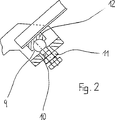
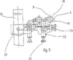
図1は本発明によるチャンネル装置の図、図2は図1のYで示された部分の拡大図、かつ図3は本発明によるチャンネル装置の懸吊ユニットを図1の矢印Xによって示された方向で見た図である。
図1に示されたチャンネル装置は、図示されないゴブをガラス機械のゴブ分配器1からガラス機械の予備成形型2内へ移送するのに使用される。図1にはこのようなチャンネル装置3が2つ示されているが、これらの機能と構成部材は等しいので、一方だけについて説明される。
ゴブ分配器1からチャンネル装置3内へゴブを移送するためにゴブ分配器1は受容チャンネル4を備えている。受容チャンネル4は先ず鉛直方向に、次いで斜め下方へ延びるように曲げられており、受容チャンネルにはチャンネル装置3が続いている。
チャンネル装置3は中央チャンネル5と変向チャンネル6とを備えている。中央チャンネル5の流入口はゴブ分配器の受容チャンネル4の流出口に、中央チャンネル5の流出口は変向チャンネル6の流入口に、かつ変向チャンネル6の流出口は予備成形型2の流入口に配設されている。
中央チャンネル5はほぼ直線形に構成され、かつゴブ分配器1の受容チャンネル4の流出口側の端部部分とほぼ同方向に延びている。中央チャンネル5はその流入口近傍で、ガラス機械のフレームと固定的に結合された支持アーム7に旋回可能に支承されている。中央チャンネル5とゴブ分配器1の受容チャンネル4の流出口側の端部部分とが互いに整列していることによってゴブ分配器1の受容チャンネル4からチャンネル装置3の中央チャンネル5内へのゴブの一様で十分に支障のない移行が保証される。
中央チャンネル5の流出口側での支承は中央チャンネル5の流出口と変向チャンネル6の流入口との間に配置された結合トラバース8を用いて行われている。結合トラバース8は中央チャンネル5の流出口とも、また変向チャンネル6の流入口とも結合されている。結合トラバース8と中央チャンネル5の流出口とを結合するために、結合トラバース8の適切な区間に特に図2に示された球形頭部支承部材9が設けられている。その球体は結合トラバース8にねじ込み可能に取付けられたねじボルト10の自由端にある。ねじボルト10を結合トラバース8へねじ込み可能に、したがって調整移動可能に取付けるために、結合トラバースはこれに不動に配置されたナット11を備えている。
ねじボルト10の中央チャンネル側の端部に配置された球形頭部支承部材9は半球形の切欠を有する支持部材12に支持されており、支持部材は中央チャンネル5の流出口側の端部部分の下面に取付けられている。そのために場合による変向チャンネル6の運動、したがってこれに結合された結合トラバース8の運動は一方では支持アーム7への中央チャンネル5の旋回可能な取付けによって、かつ他方では球形頭部支承部材9における支持部材12の全方向で適合可能な支承によって補償される。これにより変向チャンネル6の中央チャンネル5に対する空間的な位置とは無関係に、中央チャンネル5の適切な調整移動によって中央チャンネル5の流出口から変向チャンネル6の流入口内へのゴブの一様で支障のない引渡しが得られる。
変向チャンネル6の流入口側の端部部分に取付けられた結合トラバース8は懸吊装置13によって保持されており、懸吊装置自体は継ぎ手(Gelenk)14を介して、ガラス機械のフレームと不動に結合されたフレーム部分15と結合されている。
継ぎ手14は、変向チャンネル6の流入口側の端部部分の、矢印Aで示された鉛直方向、矢印Bで示された水平方向、かつ水平方向Bに垂直な、矢印Cで示された水平方向における調整移動を許す。したがって継ぎ手14によって、変向チャンネル6を、その流出口の中心軸線16が十分に予備成形型2の中心軸線17と整列するように調整移動させることが可能である。
しかし変向チャンネル6の流出口の中心軸線16とガラス機械の予備成形型2の中心軸線17との絶対的に正確な整列は可能ではないか、または継ぎ手14でのきわめて大きな調整移動の手間をかけ、かつ継ぎ手14のきわめて費用のかかる構成をもってしてのみ可能であるので、変向チャンネル6から流出口側の端部部分18が分離されている。
この流出口側の端部部分18は予備成形型2に対して空間的に固定されて配置されている。そのために流出口側の端部部分18の中心軸線19が正確に予備成形型2の中心軸線17に整列することができ、その結果流出口側の端部部分18から予備成形型2内へのゴブ(図示されていない)の正確にセンタリングされた移行が可能である。
変向チャンネル6から分離された流出口側の端部部分18の中心軸線19からの、変向チャンネルに残った流出口20の中心軸線16の方向の僅かなずれを補償するために、流出口側の端部部分18は図面に点線で書込まれたホッパ21を備えた構成になっており、ホッパは流出口側の端部部分18の流入口と流出口との間で先細になっている。これによって、残った変向チャンネル6の流出口20が変向チャンネル6から分離された流出口側の端部部分18内へ移送されたゴブがホッパ21を備えた流出口側の端部部分18の流出口でガラス機械の予備成形型2の中心軸線17と正確に整列して移動することがいずれの場合にも保証される。これによってこのゴブからガラス製品を製作する際に上記の利点が得られる。
ホッパ21を備えた流出口側の端部部分18は懸吊ユニット22に保持されている。懸吊ユニットには2つの調整移動装置23,24が設けられており、これらを用いて流出口側の端部部分18の位置がガラス機械の予備成形型2の位置に対して図3にDで示された方向でもまた同様に図3にEで示された方向でも適合せしめられる。これによって、流出口側の端部部分18の中心軸線19と予備成形型2の中心軸線17との間の正確な整列を達成することが可能である。方向DとEは互いに、かつ流出口側端部部分18の鉛直に配置された中心軸線19に対して垂直に延びている。
流出口側の端部部分18の懸吊ユニット22自体はキャリッジ25と結合されており、キャリッジはレール26上を走行可能である。このために流出口側の端部部分18を、例えばやはり交換された予備成形型に対してより良好に適合せしめられた他の端部部分で替えるのは比較的面倒ではない。The present invention relates to a channel device for transferring a gob from a gob distributor to a preform of a glass machine, wherein a central channel is provided, the inlet of the central channel being connected to a receiving channel of the gob distributor. And the central channel is inclined downwardly between its inlet and outlet, a turning channel is provided, and the turning channel inlet is connected to the central channel outlet. The direction of the outlet of the direction channel is substantially straight and the direction of the direction of the outlet of the direction channel can be adapted to the central axis of the preform of the glass machine. It relates to a type in which the channel is held on the frame part of the glass machine by a suspension device which can be adjusted and moved.
In this type of channel device known in the art, as far as possible the transfer of the gob from the turning channel into the preform is possible, the outlet of the turning channel being movable together with the turning channel, so that Attempts have been made to achieve this by allowing the outlet to be moved into alignment with the center axis of the preform. However, since the turning channel is movable with respect to the preforming die, a slight deviation occurs between the center axis of the end portion on the outlet side of the turning channel and the center axis of the preforming die. As a result, the quality of the glass product made from the gob is impaired.
It is an object of the present invention to provide a channel device for transferring a gob from a gob distributor to a glass machine preform, and to accurately center the gob from the channel device turning channel into the glass machine preform. It is to be developed so that delivery is possible.
This problem is solved by the present invention in that the end portion on the outlet side of the turning channel is separated from the turning channel and is configured as a hopper. The end portion on the outlet side of the hopper type is arranged spatially fixed to the preforming die. The remaining diverting channel is movably disposed relative to a hopper tapered on the preform side. Due to this mobility, the central axis of the outlet region of the diverting channel is positioned as much as possible in alignment with the central axis of the hopper or preform. The slight deviation between the center axis of the outlet of the turning channel and the center axis of the hopper is eliminated by the hopper action, so that the gob is accurately positioned at the end of the hopper that is spatially fixed to the preform. It exits from this end part on the central axis of the part part. Since the end portion is in a fixed spatial arrangement with respect to the preform mold, the center axis of the end portion is always aligned with the center axis of the preform mold so that the gob is precisely in the desired alignment position. Enter the preform. This provides an ideal distribution of the glass material present inside the gob within the preform. Furthermore, the end portion constructed in accordance with the present invention acts so that the gob is hardly deformed or as little as possible.
The exact alignment of the center axis of the separate hopper-shaped outlet side of the diverting channel with the center axis of the preform is such that the end of the diverting channel on the outlet side is suspended by the suspension unit. This is simple when the two adjustment movement devices that are held and provided in the suspension unit can be adjusted and moved in two axes that are perpendicular to each other and to the central axis of the end portion. It is possible in the form.
For exchanging the end portion on the separate outlet side, it is advantageous if the suspension unit is arranged on a carriage and the carriage can run on rails. This makes it possible, for example, to exchange the hopper-shaped outlet side end portion of the turning channel.
When the outlet of the central channel and the inlet of the diverting channel are connected to each other by a combined traverse and a spherical head support member is arranged between the combined traburst and the central channel, the central channel of the channel device It is possible to transfer the gob between the central axis of the deflection channel with as little trouble as possible and with little loss of quality. This ensures a proper adaptation of the outlet of the central channel even during the movement of the turning channel, thus ensuring an unobstructed transition of the gob from the outlet of the central channel into the inlet of the turning channel.
When the deflection channel suspension is connected to the frame part of the glass machine using joints that are adjustable in three axes perpendicular to each other, the outlet end region of the remaining deflection channel As accurate alignment as possible of the central axis is achievable. This further reduces the stress of the gob in the end portion of the hopper shape that is spatially fixed to the preforming die, following the remaining turning channel.
The present invention will be described in detail below with reference to the drawings with reference to the drawings.
1 is a diagram of a channel device according to the invention, FIG. 2 is an enlarged view of the portion indicated by Y in FIG. 1, and FIG. 3 is a suspension unit of the channel device according to the invention indicated by an arrow X in FIG. It is the figure seen by direction.
The channel device shown in FIG. 1 is used to transfer a gob (not shown) from a gob distributor 1 of a glass machine into a preform 2 of the glass machine. Although two such channel devices 3 are shown in FIG. 1, their functions and components are the same, so only one will be described.
In order to transfer the gob from the gob distributor 1 into the channel device 3, the gob distributor 1 is provided with a receiving channel 4. The receiving channel 4 is first bent in the vertical direction and then obliquely downward, and the receiving channel is followed by the channel device 3.
The channel device 3 includes a central channel 5 and a
The central channel 5 is configured in a substantially straight line and extends in the same direction as the end portion on the outlet side of the receiving channel 4 of the gob distributor 1. The central channel 5 is pivotally supported in the vicinity of its inlet by a support arm 7 fixedly connected to the frame of the glass machine. The central channel 5 and the end portion on the outlet side of the receiving channel 4 of the gob distributor 1 are aligned with each other so that the gob from the receiving channel 4 of the gob distributor 1 into the central channel 5 of the channel device 3 A uniform and sufficiently trouble-free transition is guaranteed.
The support on the outlet side of the central channel 5 is performed using a joint traverse 8 arranged between the outlet of the central channel 5 and the inlet of the turning
A spherical head support member 9 disposed at the end of the
The joint traverse 8 attached to the end portion on the inlet side of the turning
The
However, absolutely accurate alignment between the center axis 16 of the outlet of the
The end portion 18 on the outlet side is spatially fixed to the preform 2. For this purpose, the central axis 19 of the end part 18 on the outlet side can be precisely aligned with the
In order to compensate for a slight deviation in the direction of the central axis 16 of the
The end portion 18 on the outlet side including the hopper 21 is held by the
The
Claims (5)
Applications Claiming Priority (3)
| Application Number | Priority Date | Filing Date | Title |
|---|---|---|---|
| DE19501762.5 | 1995-01-21 | ||
| DE19501762A DE19501762C2 (en) | 1995-01-21 | 1995-01-21 | Channel arrangement for transferring a glass drop from a drop distributor to a preform of a glass machine |
| PCT/EP1996/000017 WO1996022253A1 (en) | 1995-01-21 | 1996-01-04 | Channel arrangement for transferring a drop of glass from a drop distributor to a pre-mould of a glass machine |
Publications (2)
| Publication Number | Publication Date |
|---|---|
| JPH10512230A JPH10512230A (en) | 1998-11-24 |
| JP3970320B2 true JP3970320B2 (en) | 2007-09-05 |
Family
ID=7751997
Family Applications (1)
| Application Number | Title | Priority Date | Filing Date |
|---|---|---|---|
| JP52199496A Expired - Lifetime JP3970320B2 (en) | 1995-01-21 | 1996-01-04 | Channel device for transferring gob from gob distributor to glass machine preform |
Country Status (5)
| Country | Link |
|---|---|
| US (1) | US5888267A (en) |
| EP (1) | EP0804388B1 (en) |
| JP (1) | JP3970320B2 (en) |
| DE (2) | DE19501762C2 (en) |
| WO (1) | WO1996022253A1 (en) |
Families Citing this family (8)
| Publication number | Priority date | Publication date | Assignee | Title |
|---|---|---|---|---|
| IT245774Y1 (en) * | 1998-01-13 | 2002-03-26 | Bottero Spa | DROP DELIVERY GROUP FOR A DIVETRO ARTICLES FORMING MACHINE. |
| ITTO980022A1 (en) * | 1998-01-13 | 1999-07-13 | Bottero Spa | DELIVERY UNIT FOR CONVEYING GLASS DROPS TOWARD A MOLD OF A MACHINE FOR FORMING GLASS ARTICLES. |
| US6032492A (en) * | 1998-12-03 | 2000-03-07 | Emhart Glass S.A. | I.S. machine |
| US6170295B1 (en) * | 1999-03-04 | 2001-01-09 | Emhart Glass S.A. | I.S. machine |
| US6776011B2 (en) * | 2000-08-21 | 2004-08-17 | Owens-Brockway Glass Container Inc. | Apparatus for conveying gobs of glass to a glass container forming machine |
| US7543461B2 (en) * | 2004-10-12 | 2009-06-09 | Owens-Brockway Glass Container Inc. | Variable radius deflector |
| CN105110606B (en) * | 2015-09-24 | 2017-06-16 | 山东三金玻璃机械有限公司 | A kind of individual section machine chute support of independent adjustment |
| DE202016004390U1 (en) * | 2016-07-19 | 2017-10-20 | Rolf Themann & Partner SA | Gutter system for transporting glass gobs from a feeder device to stations of a glass machine |
Family Cites Families (17)
| Publication number | Priority date | Publication date | Assignee | Title |
|---|---|---|---|---|
| US1653479A (en) * | 1927-12-20 | soubier | ||
| FR554674A (en) * | 1923-06-15 | |||
| US1331511A (en) * | 1918-06-17 | 1920-02-24 | Owens Bottle Machine Company | Apparatus for transferring glass to molds |
| US1331536A (en) * | 1918-07-08 | 1920-02-24 | Owens Bottle Machine Company | Means for transferring molten glass to molds |
| US1692553A (en) * | 1921-09-23 | 1928-11-20 | Owens Bottle Co | Glass-feeding mechanism |
| US1645221A (en) * | 1926-11-20 | 1927-10-11 | Hartford Empire Co | Method and apparatus for feeding molten glass |
| US2147307A (en) * | 1936-06-20 | 1939-02-14 | Capstan Glass Co | Charge forming machine |
| US2293860A (en) * | 1940-03-08 | 1942-08-25 | Jeannette Glass Company | Method of feeding glass |
| US2334064A (en) * | 1940-05-01 | 1943-11-09 | Gen Electric | Glass feeding apparatus |
| US2758421A (en) * | 1952-04-03 | 1956-08-14 | Owens Illinois Glass Co | Chute for conveying molten glass |
| US2873555A (en) * | 1954-01-27 | 1959-02-17 | Owens Illinois Glass Co | Chute for conveying molten glass |
| US3198617A (en) * | 1959-10-08 | 1965-08-03 | Owens Illinois Glass Co | Mechanism for pressing charges of molten glass in a forming mold |
| US3198616A (en) * | 1960-12-09 | 1965-08-03 | Owens Illinois Glass Co | Apparatus for conveying molten glass charges |
| FR2193792A1 (en) * | 1973-07-24 | 1974-02-22 | Emhart Corp | Automatic control of weight of glass articles - using tiltable tube allo-wing for variations in viscosity |
| JP2535360B2 (en) * | 1987-11-18 | 1996-09-18 | 株式会社ナべヤ | Gob guide device |
| GB2249089B (en) * | 1990-10-10 | 1994-03-30 | Vhc Ltd | Improved alignment apparatus |
| DE4116593C1 (en) * | 1991-05-22 | 1993-01-07 | Fa. Hermann Heye, 3063 Obernkirchen, De |
-
1995
- 1995-01-21 DE DE19501762A patent/DE19501762C2/en not_active Expired - Fee Related
-
1996
- 1996-01-04 EP EP96900900A patent/EP0804388B1/en not_active Expired - Lifetime
- 1996-01-04 US US08/894,218 patent/US5888267A/en not_active Expired - Lifetime
- 1996-01-04 JP JP52199496A patent/JP3970320B2/en not_active Expired - Lifetime
- 1996-01-04 DE DE59600806T patent/DE59600806D1/en not_active Expired - Lifetime
- 1996-01-04 WO PCT/EP1996/000017 patent/WO1996022253A1/en active IP Right Grant
Also Published As
| Publication number | Publication date |
|---|---|
| DE59600806D1 (en) | 1998-12-17 |
| US5888267A (en) | 1999-03-30 |
| DE19501762C2 (en) | 1997-04-30 |
| DE19501762A1 (en) | 1996-07-25 |
| EP0804388B1 (en) | 1998-11-11 |
| WO1996022253A1 (en) | 1996-07-25 |
| EP0804388A1 (en) | 1997-11-05 |
| JPH10512230A (en) | 1998-11-24 |
Similar Documents
| Publication | Publication Date | Title |
|---|---|---|
| CA1168453A (en) | Pressurized fluid distributing arrangement for a forming tool for shaping thermoplastic material | |
| JP3970320B2 (en) | Channel device for transferring gob from gob distributor to glass machine preform | |
| JP3295167B2 (en) | Trough equipment | |
| CA1081959A (en) | Glassware forming machine of the i.s. type with in- line mold motion | |
| JPH042528B2 (en) | ||
| US20120111424A1 (en) | Module for Transferring a Component Between Two Positions | |
| JPH0789736A (en) | Glass gob guide apparatus for glass bottle molding machine | |
| JP3920934B2 (en) | Trough assembly for glassware manufacturing equipment | |
| US4969945A (en) | Holder for the mold halves of an IS machine for making hollow glass articles | |
| JPH0653575B2 (en) | A movement mechanism used in an industrial section type glass product manufacturing machine. | |
| US6318130B1 (en) | Liquid cooling of deflectors in a glassware forming system | |
| JP3976801B2 (en) | Baffle mounting equipment in glassware manufacturing equipment | |
| JP4361994B2 (en) | I. S. Glass forming machine | |
| US20060179884A1 (en) | Glassware forming machine mold cooling apparatus and method | |
| AU733505B2 (en) | Plunger base module for a plunger mechanism of an I.S. machine | |
| JP4322389B2 (en) | I. S. Glass bottle making machine | |
| JPS60500809A (en) | Warping plate adjustment device for glass container forming machine | |
| EP0121346A1 (en) | Blow mould cooling | |
| CZ295176B6 (en) | Method for forming cased glass stream and apparatus for making the same |
Legal Events
| Date | Code | Title | Description |
|---|---|---|---|
| TRDD | Decision of grant or rejection written | ||
| A01 | Written decision to grant a patent or to grant a registration (utility model) |
Free format text: JAPANESE INTERMEDIATE CODE: A01 Effective date: 20070515 |
|
| A61 | First payment of annual fees (during grant procedure) |
Free format text: JAPANESE INTERMEDIATE CODE: A61 Effective date: 20070606 |
|
| R150 | Certificate of patent or registration of utility model |
Free format text: JAPANESE INTERMEDIATE CODE: R150 |
|
| FPAY | Renewal fee payment (event date is renewal date of database) |
Free format text: PAYMENT UNTIL: 20100615 Year of fee payment: 3 |
|
| FPAY | Renewal fee payment (event date is renewal date of database) |
Free format text: PAYMENT UNTIL: 20110615 Year of fee payment: 4 |
|
| FPAY | Renewal fee payment (event date is renewal date of database) |
Free format text: PAYMENT UNTIL: 20120615 Year of fee payment: 5 |
|
| FPAY | Renewal fee payment (event date is renewal date of database) |
Free format text: PAYMENT UNTIL: 20130615 Year of fee payment: 6 |
|
| R250 | Receipt of annual fees |
Free format text: JAPANESE INTERMEDIATE CODE: R250 |
|
| R250 | Receipt of annual fees |
Free format text: JAPANESE INTERMEDIATE CODE: R250 |
|
| R250 | Receipt of annual fees |
Free format text: JAPANESE INTERMEDIATE CODE: R250 |
|
| EXPY | Cancellation because of completion of term |