EP0803760B1 - Dispositif pour l'atténuation locale de l'intensité de la lumière - Google Patents
Dispositif pour l'atténuation locale de l'intensité de la lumière Download PDFInfo
- Publication number
- EP0803760B1 EP0803760B1 EP97101584A EP97101584A EP0803760B1 EP 0803760 B1 EP0803760 B1 EP 0803760B1 EP 97101584 A EP97101584 A EP 97101584A EP 97101584 A EP97101584 A EP 97101584A EP 0803760 B1 EP0803760 B1 EP 0803760B1
- Authority
- EP
- European Patent Office
- Prior art keywords
- flc
- liquid crystal
- oaslm
- ferroelectric
- light modulator
- Prior art date
- Legal status (The legal status is an assumption and is not a legal conclusion. Google has not performed a legal analysis and makes no representation as to the accuracy of the status listed.)
- Expired - Lifetime
Links
- 239000004973 liquid crystal related substance Substances 0.000 claims abstract description 10
- 239000005262 ferroelectric liquid crystals (FLCs) Substances 0.000 claims description 50
- 230000003287 optical effect Effects 0.000 claims description 23
- 239000004990 Smectic liquid crystal Substances 0.000 claims description 21
- 230000000007 visual effect Effects 0.000 claims 3
- 230000005540 biological transmission Effects 0.000 claims 2
- 239000011521 glass Substances 0.000 description 10
- 239000000463 material Substances 0.000 description 10
- 230000000694 effects Effects 0.000 description 7
- 230000010287 polarization Effects 0.000 description 5
- 238000010586 diagram Methods 0.000 description 4
- 238000000034 method Methods 0.000 description 4
- 239000004988 Nematic liquid crystal Substances 0.000 description 3
- 210000002858 crystal cell Anatomy 0.000 description 3
- 230000004313 glare Effects 0.000 description 3
- SBIBMFFZSBJNJF-UHFFFAOYSA-N selenium;zinc Chemical compound [Se]=[Zn] SBIBMFFZSBJNJF-UHFFFAOYSA-N 0.000 description 3
- 230000002269 spontaneous effect Effects 0.000 description 3
- 230000007704 transition Effects 0.000 description 3
- 210000004027 cell Anatomy 0.000 description 2
- 230000005693 optoelectronics Effects 0.000 description 2
- 230000008569 process Effects 0.000 description 2
- 239000000758 substrate Substances 0.000 description 2
- 238000003466 welding Methods 0.000 description 2
- 0 CC1*CCC1 Chemical compound CC1*CCC1 0.000 description 1
- 229920000742 Cotton Polymers 0.000 description 1
- 239000004372 Polyvinyl alcohol Substances 0.000 description 1
- 230000008859 change Effects 0.000 description 1
- 239000004744 fabric Substances 0.000 description 1
- 229910052736 halogen Inorganic materials 0.000 description 1
- AMGQUBHHOARCQH-UHFFFAOYSA-N indium;oxotin Chemical compound [In].[Sn]=O AMGQUBHHOARCQH-UHFFFAOYSA-N 0.000 description 1
- 230000002452 interceptive effect Effects 0.000 description 1
- 230000007935 neutral effect Effects 0.000 description 1
- 229920002451 polyvinyl alcohol Polymers 0.000 description 1
- 230000001681 protective effect Effects 0.000 description 1
- 239000010453 quartz Substances 0.000 description 1
- 230000004044 response Effects 0.000 description 1
- 239000005336 safety glass Substances 0.000 description 1
- 238000010008 shearing Methods 0.000 description 1
- VYPSYNLAJGMNEJ-UHFFFAOYSA-N silicon dioxide Inorganic materials O=[Si]=O VYPSYNLAJGMNEJ-UHFFFAOYSA-N 0.000 description 1
- 238000001228 spectrum Methods 0.000 description 1
- 238000004528 spin coating Methods 0.000 description 1
- 230000009466 transformation Effects 0.000 description 1
- 238000000844 transformation Methods 0.000 description 1
- 229910052721 tungsten Inorganic materials 0.000 description 1
- 239000010937 tungsten Substances 0.000 description 1
- -1 tungsten halogen Chemical class 0.000 description 1
- 238000004804 winding Methods 0.000 description 1
Images


Classifications
-
- G—PHYSICS
- G02—OPTICS
- G02C—SPECTACLES; SUNGLASSES OR GOGGLES INSOFAR AS THEY HAVE THE SAME FEATURES AS SPECTACLES; CONTACT LENSES
- G02C7/00—Optical parts
- G02C7/10—Filters, e.g. for facilitating adaptation of the eyes to the dark; Sunglasses
- G02C7/101—Filters, e.g. for facilitating adaptation of the eyes to the dark; Sunglasses having an electro-optical light valve
-
- A—HUMAN NECESSITIES
- A61—MEDICAL OR VETERINARY SCIENCE; HYGIENE
- A61F—FILTERS IMPLANTABLE INTO BLOOD VESSELS; PROSTHESES; DEVICES PROVIDING PATENCY TO, OR PREVENTING COLLAPSING OF, TUBULAR STRUCTURES OF THE BODY, e.g. STENTS; ORTHOPAEDIC, NURSING OR CONTRACEPTIVE DEVICES; FOMENTATION; TREATMENT OR PROTECTION OF EYES OR EARS; BANDAGES, DRESSINGS OR ABSORBENT PADS; FIRST-AID KITS
- A61F9/00—Methods or devices for treatment of the eyes; Devices for putting in contact-lenses; Devices to correct squinting; Apparatus to guide the blind; Protective devices for the eyes, carried on the body or in the hand
- A61F9/02—Goggles
- A61F9/022—Use of special optical filters, e.g. multiple layers, filters for protection against laser light or light from nuclear explosions, screens with different filter properties on different parts of the screen; Rotating slit-discs
- A61F9/023—Use of special optical filters, e.g. multiple layers, filters for protection against laser light or light from nuclear explosions, screens with different filter properties on different parts of the screen; Rotating slit-discs with variable transmission, e.g. photochromic
-
- G—PHYSICS
- G02—OPTICS
- G02B—OPTICAL ELEMENTS, SYSTEMS OR APPARATUS
- G02B26/00—Optical devices or arrangements for the control of light using movable or deformable optical elements
- G02B26/02—Optical devices or arrangements for the control of light using movable or deformable optical elements for controlling the intensity of light
-
- G—PHYSICS
- G02—OPTICS
- G02F—OPTICAL DEVICES OR ARRANGEMENTS FOR THE CONTROL OF LIGHT BY MODIFICATION OF THE OPTICAL PROPERTIES OF THE MEDIA OF THE ELEMENTS INVOLVED THEREIN; NON-LINEAR OPTICS; FREQUENCY-CHANGING OF LIGHT; OPTICAL LOGIC ELEMENTS; OPTICAL ANALOGUE/DIGITAL CONVERTERS
- G02F1/00—Devices or arrangements for the control of the intensity, colour, phase, polarisation or direction of light arriving from an independent light source, e.g. switching, gating or modulating; Non-linear optics
- G02F1/01—Devices or arrangements for the control of the intensity, colour, phase, polarisation or direction of light arriving from an independent light source, e.g. switching, gating or modulating; Non-linear optics for the control of the intensity, phase, polarisation or colour
- G02F1/13—Devices or arrangements for the control of the intensity, colour, phase, polarisation or direction of light arriving from an independent light source, e.g. switching, gating or modulating; Non-linear optics for the control of the intensity, phase, polarisation or colour based on liquid crystals, e.g. single liquid crystal display cells
- G02F1/133—Constructional arrangements; Operation of liquid crystal cells; Circuit arrangements
- G02F1/135—Liquid crystal cells structurally associated with a photoconducting or a ferro-electric layer, the properties of which can be optically or electrically varied
-
- G—PHYSICS
- G02—OPTICS
- G02F—OPTICAL DEVICES OR ARRANGEMENTS FOR THE CONTROL OF LIGHT BY MODIFICATION OF THE OPTICAL PROPERTIES OF THE MEDIA OF THE ELEMENTS INVOLVED THEREIN; NON-LINEAR OPTICS; FREQUENCY-CHANGING OF LIGHT; OPTICAL LOGIC ELEMENTS; OPTICAL ANALOGUE/DIGITAL CONVERTERS
- G02F1/00—Devices or arrangements for the control of the intensity, colour, phase, polarisation or direction of light arriving from an independent light source, e.g. switching, gating or modulating; Non-linear optics
- G02F1/01—Devices or arrangements for the control of the intensity, colour, phase, polarisation or direction of light arriving from an independent light source, e.g. switching, gating or modulating; Non-linear optics for the control of the intensity, phase, polarisation or colour
- G02F1/13—Devices or arrangements for the control of the intensity, colour, phase, polarisation or direction of light arriving from an independent light source, e.g. switching, gating or modulating; Non-linear optics for the control of the intensity, phase, polarisation or colour based on liquid crystals, e.g. single liquid crystal display cells
- G02F1/137—Devices or arrangements for the control of the intensity, colour, phase, polarisation or direction of light arriving from an independent light source, e.g. switching, gating or modulating; Non-linear optics for the control of the intensity, phase, polarisation or colour based on liquid crystals, e.g. single liquid crystal display cells characterised by the electro-optical or magneto-optical effect, e.g. field-induced phase transition, orientation effect, guest-host interaction or dynamic scattering
- G02F1/139—Devices or arrangements for the control of the intensity, colour, phase, polarisation or direction of light arriving from an independent light source, e.g. switching, gating or modulating; Non-linear optics for the control of the intensity, phase, polarisation or colour based on liquid crystals, e.g. single liquid crystal display cells characterised by the electro-optical or magneto-optical effect, e.g. field-induced phase transition, orientation effect, guest-host interaction or dynamic scattering based on orientation effects in which the liquid crystal remains transparent
- G02F1/141—Devices or arrangements for the control of the intensity, colour, phase, polarisation or direction of light arriving from an independent light source, e.g. switching, gating or modulating; Non-linear optics for the control of the intensity, phase, polarisation or colour based on liquid crystals, e.g. single liquid crystal display cells characterised by the electro-optical or magneto-optical effect, e.g. field-induced phase transition, orientation effect, guest-host interaction or dynamic scattering based on orientation effects in which the liquid crystal remains transparent using ferroelectric liquid crystals
Definitions
- the invention relates to a device for local Attenuation of the light intensity in the field of view of the human eye, from video or photo cameras or the like according to the preamble of claim 1 2 or 3.
- the photosensitive matrices must be up to before glare towards damage due to incidence of light too high Intensity are protected.
- the usual safety devices used in this regard have numerous disadvantages: neutral or polarizing filters decrease proportionally to Brightness of interfering light also the brightness of the objects to be observed. Will the exposure reduced, these filters are removed mechanically.
- the well-known glasses with automatic switching on Limit absorbing filters in strong light the entire field of view. A better protective effect the local attenuation of brightness is strong exposed objects that are in the field of view of the eye Video camera and so on, without being at the same time suppress low-light objects.
- the light modulator comprises two Polarizers, between which there is one on the Lens side with a transparent photoconductive Layer provided liquid crystal cell, which is delimited by two transparent plates on which Electrodes are attached.
- the liquid crystal cell has a chiral nematic between the plates Liquid crystal.
- the invention has for its object a improved and faster device for local Attenuation of light intensity for the to create a wide variety of applications to do this Deformation of the ferroelectric helix uses.
- the device proposed in this invention utilizes a much faster electro-optical effect in ferroelectric liquid crystals, namely the deformation of the ferroelectric helix (DHF effect), which was described by LA Beresnev et al in the above-mentioned technical article in Liquid Crystals, 5, p. 1171, (1989).
- DHF effect deformation of the ferroelectric helix
- This effect is characteristic of chiral smectic-C materials with a very short rise height p o the helix (0.3 ⁇ m or less) and has great advantages over the electro-optical effects in nemates.
- the safety device according to the present invention is significantly faster than devices based on nematic liquid crystals.
- the operating frequency is in the range of approx. 10 2 to 10 3 Hz instead of 1-20 Hz for the Nematen. This results in the possibility of avoiding the blurring (blurring) of the image during the observation of strongly moving exposed objects and the glare of the eye or the video camera.
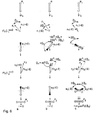
- FIG. 1 shows a general representation of glasses with local attenuation of high light intensity with the aid of optically addressable spatial light modulators OASLM. It also consists of lenses L 1 , L 2 , L 3 , polarizers P 1 , P 2 , photoconductors PC and ferroelectric liquid crystals FLC.
- OASLM optically addressable spatial light modulators
- It also consists of lenses L 1 , L 2 , L 3 , polarizers P 1 , P 2 , photoconductors PC and ferroelectric liquid crystals FLC.
- the following scenario is assumed as an exit: highly exposed image - the sun, weakly exposed image - a house. After passing through the polarizer P 2 , the intensity of the image of the sun is reduced compared to that of the house.
- the optically addressable spatial light modulator OASLM shown in FIG. 1 is based on a photoconductive layer PC and a liquid crystal film FLC.
- a photoconductive layer PC which touches the photoconductive layer PC
- the light from weakly exposed objects (“house”) can pass through the crossed polarizers P 1 and P 2 .
- the light from strongly exposed objects (“sun”), focused on the layer PC induces the local transition from the twisted to the homeotropic state in the layer FLC due to the voltage externally applied to the optically addressable spatial light modulator OASLM.
- the transition twisted - homeotropic - takes place only at the point of the optically addressable spatial light modulator OASLM, at which the conductivity of the photoconductor PC increases due to the strong exposure ("sun"). At this point, the light does not pass through the polarizer P 2 , the brightness of the strongly exposed object (“sun”) is weakened in the resulting image.
- the lenses L 2 and L 3 represent the simplest "eye” 1 for viewing this image.
- the optical design of the system may be more complicated, depending on the size and shape requirements of the glasses (prisms, mirrors, etc. can be installed).
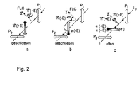
- the middle optical indicatrix runs almost parallel to the direction of the undisturbed helix z (FIG. 2c), which means that almost all of the light is transmitted.
- the plane of polarization of light e ( ⁇ E) is rotated by 90 °.
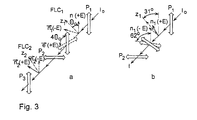
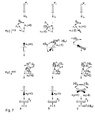
- Fig. 3 shows the mode of operation when using DHF-LC material with a molecular angle of inclination ⁇ o ⁇ 45 °.
- ⁇ E positive polarity
- ⁇ E director n 1 runs in layer FLC 1 .
- the director n 2 (-E) of the shutter 2 coincides with the polarizer P 2 . As a result, no light falls through the polarizer P 3 .
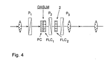
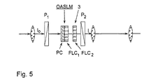
- FIG. 5 shows the optical diagram of the glasses or device with the fast switchable "compensator” 3, where the layer FLC 1 assumes a molecular angle of inclination of ⁇ o ⁇ 45 °.
- the second layer FLC 2 functions as a switchable "compensator” 3, which is the polarization plane e (-E) of the light, which emanates from the strongly exposed areas of the photoconductor in the layer FLC 1 , turns back in the direction U 1 (+ E). In this case, the strongly exposed images are completely suppressed at both polarities of the meander voltage.
- FIG. 6a and b show the position of the director n 1 ( ⁇ E) of the first layer FLC 1 .
- the plane of the polarized light e 2 ( ⁇ E) that passes through the layer FLC 2 is perpendicular to that of the polarizer P 2 . That is why the passage of light is prevented in highly exposed areas of the optically addressable spatial light modulator OASLM.
- 6c shows the small deviation of the director n 1 ( ⁇ E) from the direction z 1 of the helix axis in the layer FLC 2 in weakly exposed areas of the optically addressable spatial light modulator OASLM.
- the light intensity I emanating from these areas is the same for both voltage polarities II o sin 2 (2 ⁇ o ). I o - intensity of the light that falls on the optically addressable spatial light modulator OASLM.
- I I o sin 2 (2 ⁇ o ).
- OASLM optically addressable spatial light modulators used in this scheme consist of two quartz plates with transparent indium-tin oxide electrodes. In one of the electrodes, a quasi-amorphous ZnSe film with a thickness of 1 ⁇ m is used as the photoconductive layer, identified in FIG. 4 as a PC. To achieve optical uniformity of the FLC layer, a polyvinyl alcohol film was applied to circular substrates with a diameter of 35 mm by means of a spin coating process.
- the FLC layer has exactly the geometry of a book-shelf for relatively small values of spontaneous polarization or that of a "dislocation domain structure" for higher spontaneous polarization as described by LA Beresnev, E. Schumacher, SA Pikin, Z. Fan, BI Ostrovsky, S. Hiller, AP Onokhov and W. Haase in Jpn. J. Appl. Phys., Volume 34, Part 1, No. 5A, May 1995.
- FIG. 8a is a selected image of the test target image 0683, focused on the optically addressable spatial light modulator OASLM, based on ZnSe + DHF; the thickness of the FLC layer is 5.5 ⁇ , the amplitude of the applied AC voltage (meander) is ⁇ 7.5 V, whose Frequency 50 Hz.
- the size of the picture is 1.5 x 1.5 mm.
- the numbers in the pictures 100, 200, 150 correspond to the spatial resolution 20, 40 or 30 pl / mm.
- (Fig. 8b-d) - selected image of the test target image can be registered with moving optically addressable spatial Light modulator OASLM.
- the optically addressable spatial Light modulator OASLM moves from top to bottom.
- the dot in the square belongs to the optically addressable one spatial light modulator OASLM and serves as a reference point.
- FIG. 8 shows the basic features of the manufactured optically addressable spatial Light modulator OASLM described.
- the blue light was to record the test target image and the red light to Read out the resulting image used.
- the spatial resolution of the optically addressable so obtained spatial light modulator OASLM is higher than 40 pl / mm a modulation depth of approx. 50%.
- the resolution for only a polarity of the operating voltage can be higher than 100 pl / mm at the same modulation depth.
- the limit is limited by the optical scheme of the projection.
- 8b-d show the "read-out" images when moving of the optically addressable spatial light modulator OASLM represented with regard to the test target image.
- OASLM optically addressable spatial light modulator
- a tungsten halogen lamp of 100 W is used as a very bright image.
- a white paper with an inscription (“goggles") is placed behind the lamp.
- a green filter is connected between the lens L 3 and the video camera in order to suppress the infrared and ultraviolet regions of the light spectrum which pass through the polarizers P 1 and P 3 .
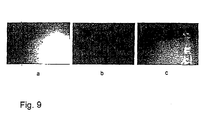
- Fig. 9 shows the operation of the safety device with local attenuation of the brightness of images greatly exposed objects using optical addressable spatial light modulators OASLM on the Basis of a photoconductive film (ZnSe), thickness ⁇ 1 ⁇ m, using the DHF effect in FLC's, thickness of the FLC Layer 5.5 ⁇ m. "With lock" scheme; (see Fig.
- Fig. 9 it is shown that during the application of electrical voltage on the optically addressable spatial light modulator OASLM the brightness of very brightly lit objects (filament) actually is suppressed while the brightness of weaker illuminated objects (paper with the word “goggles”) do not is suppressed. So the text is clearly visible without the video camera is blinded. For comparison, it will same image contrasted when looking at the addressable spatial light modulator OASLM none Voltage is applied. In this case, the brightness the lamp too strong to recognize the text because the video camera is blinded.
- the aperture FLC 2 of the device closes 5 ⁇ 10 ms after the response of the optically addressable spatial light modulator OASLM.
- the polarity of the voltage applied to the optically addressable spatial light modulator OASLM changes.
- the entire cycle is repeated after 10-20 ms.
- the device works up to a meandering frequency of 1 kHz when the fine adjustment for the bias field has taken place and the optically addressable spatial light modulator OASLM is located between the crossed polarizers P 1 and P 2 .
- These high frequencies offer the possibility of observing the movement of poorly illuminated objects against the background of strongly illuminated objects, such as the sun, lamps, etc., without the images becoming blurred and the eye or video camera 1 being blinded.
- the device can not only be successfully used to implement optical controllers in optical telecommunications lines, but also for welding and cutting torch work, as well as for other activities in which high local light intensities occur.
Landscapes
- Physics & Mathematics (AREA)
- Health & Medical Sciences (AREA)
- Optics & Photonics (AREA)
- General Physics & Mathematics (AREA)
- Ophthalmology & Optometry (AREA)
- Nonlinear Science (AREA)
- General Health & Medical Sciences (AREA)
- Animal Behavior & Ethology (AREA)
- Vascular Medicine (AREA)
- Life Sciences & Earth Sciences (AREA)
- Heart & Thoracic Surgery (AREA)
- Biomedical Technology (AREA)
- Public Health (AREA)
- Veterinary Medicine (AREA)
- Mathematical Physics (AREA)
- Chemical & Material Sciences (AREA)
- Crystallography & Structural Chemistry (AREA)
- Engineering & Computer Science (AREA)
- Liquid Crystal (AREA)
- Optical Communication System (AREA)
Claims (9)
- Dispositif d'atténuation locale de l'intensité lumineuse, dans le champ de vision de l'oeil humain, pour des caméras vidéo, des appareils photographiques ou similaires ou des appareils photosensibles d'observation et d'enregistrement de figures éclairées, constitué de lentilles et de filtres, dans lequel, entre un objectif constitué d'une ou plusieurs lentilles (L1) et deux polariseurs à prismes croisés (P1 et P2), est disposé un modulateur de lumière spatial optiquement adressable (OASLM), qui comprend deux plaques transparentes dotées d'électrodes et une couche photoconductrice semi-transparente (PC),
caractérisé en ce que
le modulateur de lumière (OASLM) est pourvu d'un cristal liquide (CL) smectique, ferroélectrique, en forme d'hélice, qui est disposé entre les plaques suivant une géométrie d'empilement et/ou une géométrie des domaines de déformation, l'axe de l'hélice du cristal liquide smectique (CL) est parallèle aux plaques, l'angle d'inclinaison moléculaire 0 de la couche de cristal liquide (CL) est de 45° et le sens de frottement z forme avec le polariseur (P1) un angle de 45°. - Dispositif d'atténuation locale de l'intensité lumineuse dans le champ de vision de l'oeil humain, pour des caméras vidéo, des appareils photographiques ou similaires ou des appareils photosensibles d'observation et d'enregistrement de figures éclairées, constitué de lentilles et de filtres, dans lequel, entre un objectif constitué d'une ou plusieurs lentilles (L1) et deux polariseurs à prismes croisés (P1 et P2), est disposé un modulateur de lumière spatial optiquement adressable (OASLM), qui comprend deux plaques transparentes dotées d'électrodes et une couche photoconductrice semi-transparente (PC),
caractérisé en ce que
le modulateur de lumière (OASLM) est pourvu d'un cristal liquide (CL) smectique, ferroélectrique, en forme d'hélice, qui est disposé entre les plaques suivant une géométrie d'empilement et/ou une géométrie des domaines de déformation, l'axe de l'hélice du cristal liquide smectique (CL) est parallèle aux plaques et, pour empêcher la propagation de la lumière, un élément d'obturation (2) est prévu dans le dispositif pour assurer la contre-polarité de la tension appliquée aux électrodes mentionnées. - Dispositif d'atténuation locale de l'intensité lumineuse dans le champ de vision de l'oeil humain, pour des caméras vidéo, des appareils photographiques ou similaires ou des appareils photosensibles d'observation et d'enregistrement de figures éclairées, constitué de lentilles et de filtres, dans lequel, entre un objectif constitué d'une ou plusieurs lentilles (L1)et deux polariseurs à prismes croisés (P1 et P2), est disposé un modulateur de lumière spatial optiquement adressable (OASLM), qui comprend deux plaques transparentes dotées d'électrodes et une couche photoconductrice semi-transparente (PC),
caractérisé en ce que
le modulateur de lumière (OASLM) est pourvu d'un cristal liquide (CL) smectique, ferroélectrique, en forme d'hélice, qui est disposé entre les plaques suivant une géométrie d'empilement et/ou une géométrie des domaines de déformation, l'axe de l'hélice du cristal liquide smectique (CL1) est parallèle aux plaques et une deuxième couche de cristal liquide smectique, chiral, ferroélectrique (CL2), qui se trouve entre deux autres plaques transparentes dotées d'électrodes, est disposée entre le modulateur de lumière spatial optiquement adressable (OASLM) et un des polariseurs mentionnés (P1, P2). - Dispositif selon la revendication 3, caractérisé en ce que, dans une condition de fort éclairage, pour les deux polarités de tension appliquées aux électrodes, les propriétés optiques du second cristal liquide (CL2) smectique, chiral, ferroélectrique sont réglées de façon à ce que toute transmission de lumière dans le dispositif soit empêchée.
- Dispositif selon l'une des revendications 3 ou 4, caractérisé en ce que le second cristal liquide (CL2) smectique, ferroélectrique se trouve dans la phase C smectique ferroélectrique avec un angle d'inclinaison moléculaire de 45° - 0 ou 0 , 0 représentant l'angle d'inclinaison moléculaire dudit cristal liquide (CL1) smectique ferroélectrique dans le modulateur de lumière spatial optiquement adressable (OASLM).
- Dispositif selon la revendication 4, caractérisé en ce que le second cristal liquide smectique (CL2) se trouve dans la phase smectique A chirale.
- Dispositif selon l'une des revendications précédentes, caractérisé en ce que le cristal liquide smectique ferroélectrique (CL1) se trouve dans la phase smectique C inclinée.
- Dispositif selon la revendication 2, caractérisé en ce que l'élément d'obturation (2) est conçu sous forme d'une autre couche de cristal liquide ferroélectrique (CL2) qui se trouve pour sa part entre deux plaques transparentes dotées d'électrodes et qui est positionnée entre une des couches polarisantes ou polariseurs mentionnés (P1 et P2) et une troisième couche polarisante ou un polariseur (P3).
- Dispositif selon la revendication 9, caractérisé en ce que le second cristal liquide ferroélectrique (CL2) se trouve dans une phase smectique C chirale ou dans une phase smectique A.
Applications Claiming Priority (2)
| Application Number | Priority Date | Filing Date | Title |
|---|---|---|---|
| DE19616323A DE19616323A1 (de) | 1996-04-24 | 1996-04-24 | Vorrichtung zur lokalen Abschwächung der Lichtintensität |
| DE19616323 | 1996-04-24 |
Publications (3)
| Publication Number | Publication Date |
|---|---|
| EP0803760A2 EP0803760A2 (fr) | 1997-10-29 |
| EP0803760A3 EP0803760A3 (fr) | 1998-10-14 |
| EP0803760B1 true EP0803760B1 (fr) | 2004-09-15 |
Family
ID=7792279
Family Applications (1)
| Application Number | Title | Priority Date | Filing Date |
|---|---|---|---|
| EP97101584A Expired - Lifetime EP0803760B1 (fr) | 1996-04-24 | 1997-02-01 | Dispositif pour l'atténuation locale de l'intensité de la lumière |
Country Status (4)
| Country | Link |
|---|---|
| US (1) | US6031588A (fr) |
| EP (1) | EP0803760B1 (fr) |
| AT (1) | ATE276535T1 (fr) |
| DE (2) | DE19616323A1 (fr) |
Families Citing this family (14)
| Publication number | Priority date | Publication date | Assignee | Title |
|---|---|---|---|---|
| FR2773226B1 (fr) * | 1997-12-30 | 2002-01-18 | Thomson Csf | Systeme de protection et dispositif optique de vision comprenant ce systeme de protection |
| DE19815337C2 (de) * | 1998-04-06 | 2001-07-05 | Deutsche Telekom Ag | Vorrichtung zur lokalen Abschwächung der Lichtintensität im Sehfeld einer lichtempfindlichen Beobachtungseinrichtung |
| DE19931989A1 (de) * | 1999-07-09 | 2001-01-11 | Deutsche Telekom Ag | Verfahren und Vorrichtung zur Formung des Intensitätsprofils eines Laserstrahls |
| DE19933397A1 (de) * | 1999-07-21 | 2001-01-25 | Lothar Ertl | Augenschutzvorrichtung |
| DE19952945B4 (de) * | 1999-11-03 | 2006-07-13 | Siemens Ag | System zum Eliminieren von Blendungen einer eine Szene durch eine Scheibe hindurch beobachtenden Person sowie Scheibe |
| SE515709C2 (sv) * | 2000-02-11 | 2001-10-01 | Nekp Sweden Ab | Skyddsanordning vid metallsvetsning eller - skärning |
| US7369773B2 (en) * | 2000-05-24 | 2008-05-06 | Purdue Research Foundation | Methods and systems for polarization control and polarization mode dispersion compensation for wideband optical signals |
| DE10125779A1 (de) | 2001-05-26 | 2003-01-02 | Deutsche Telekom Ag | Verfahren und Vorrichtung zur intensitätsabhängigen Abschwächung von Licht |
| FR2912230B1 (fr) * | 2007-02-02 | 2009-04-03 | Ensmse | Dispositif d'obturation electro-optique pour systeme anti-eblouissement a base d'au moins une couche photosensible. |
| DE102010006661B4 (de) | 2010-02-03 | 2019-08-01 | Diehl Defence Gmbh & Co. Kg | Verfahren und Vorrichtung zum Abbilden einer Umgebung auf eine Detektoreinrichtung |
| DE102010006664A1 (de) * | 2010-02-03 | 2011-08-04 | Diehl BGT Defence GmbH & Co. KG, 88662 | Verfahren und Vorrichtung zum Abbilden einer Umgebung auf eine Detektoreinrichtung |
| NL2007687C2 (en) | 2011-10-31 | 2013-05-07 | House Of Innovation B V | Multi spectral vision aid. |
| RU2503050C1 (ru) * | 2012-05-30 | 2013-12-27 | Игорь Николаевич Компанец | Видеопроектор |
| CN105589202A (zh) * | 2016-03-18 | 2016-05-18 | 京东方科技集团股份有限公司 | 一种显示装置、显示方法和显示系统 |
Family Cites Families (27)
| Publication number | Priority date | Publication date | Assignee | Title |
|---|---|---|---|---|
| US3661442A (en) * | 1969-03-25 | 1972-05-09 | Hitachi Ltd | Electrically operated optical shutter |
| JPS58134578A (ja) * | 1982-02-05 | 1983-08-10 | Nippon Kogaku Kk <Nikon> | テレビジヨンカメラ用フイルタ装置 |
| US4462661A (en) * | 1982-02-23 | 1984-07-31 | Instrument Flight Research | Laser protection goggles |
| HUT36381A (en) * | 1982-10-04 | 1985-09-30 | Zeiss Jena Veb Carl | Anti-dazzle spectacles |
| DE3437704A1 (de) * | 1984-01-02 | 1985-07-11 | Jenoptik Jena Gmbh, Ddr 6900 Jena | Empfaengereinheit fuer eine blendschutzbrille |
| FR2611389B1 (fr) * | 1987-02-27 | 1989-04-28 | Thomson Csf | Dispositif imageur matriciel a cristaux liquides a resolution doublee par birefringence |
| DE3721751A1 (de) * | 1987-07-01 | 1989-01-12 | Eps Elektronik | Optoelektronisches filter vorzugsweise fuer videokameras |
| FR2617990B1 (fr) * | 1987-07-07 | 1991-04-05 | Siegfried Klein | Appareil pour la vue |
| US4848890A (en) * | 1987-08-27 | 1989-07-18 | Grumman Aerospace Corporation | Visor with point sun blocking |
| FR2626385B1 (fr) * | 1988-01-22 | 1991-10-11 | Thomson Csf | Obturateur selectif de lumiere, procede de realisation et son application a un detecteur d'image |
| DE68919249T2 (de) * | 1988-03-23 | 1995-03-23 | Seiko Instr Inc | Optisch geschaltete ferroelektrische Flüssigkeitskristallichtabsperrvorrichtung. |
| JPH02108019A (ja) * | 1988-10-17 | 1990-04-19 | Semiconductor Energy Lab Co Ltd | 強誘電性液晶電気光学装置 |
| US4968127A (en) * | 1988-11-23 | 1990-11-06 | Russell James P | Controllable, variable transmissivity eyewear |
| JP2738724B2 (ja) * | 1988-11-25 | 1998-04-08 | 松下電器産業株式会社 | 空間光変調素子及び神経ネットワーク回路 |
| FR2655163A1 (fr) * | 1989-11-30 | 1991-05-31 | Scanera Ste Civile Rech | Dispositif de visualisation en faibles eclairements a couches de materiaux photo-electriques et electro-optiques. |
| US5015086A (en) * | 1989-04-17 | 1991-05-14 | Seiko Epson Corporation | Electronic sunglasses |
| US5081542A (en) * | 1989-12-12 | 1992-01-14 | Hughes Aircraft Company | Liquid crystal light valve goggles for eye protection |
| FR2661755B1 (fr) * | 1990-05-02 | 1992-07-03 | Thomson Csf | Modulateur spatial de lumiere a base de polymere photoconducteur. |
| US5073010A (en) * | 1990-05-11 | 1991-12-17 | University Of Colorado Foundation, Inc. | Optically addressable spatial light modulator having a distorted helix ferroelectric liquid crystal member |
| JP3010392B2 (ja) * | 1991-07-08 | 2000-02-21 | セイコーインスツルメンツ株式会社 | 空間光変調器とその駆動方法 |
| US5608567A (en) * | 1991-11-05 | 1997-03-04 | Asulab S.A. | Variable transparency electro-optical device |
| US5353080A (en) * | 1992-11-02 | 1994-10-04 | Christman Ernest H | Exposure-equalizing system for photographic images |
| US5298732A (en) * | 1993-02-18 | 1994-03-29 | Emee, Inc. | Automatic visor for continuously repositioning a shading object to shade a designated location from a direct radiation source |
| DE4305807A1 (de) * | 1993-02-25 | 1994-10-13 | Thomson Brandt Gmbh | Kamera mit einer steuerbaren Blende |
| CH687809A5 (de) * | 1993-05-14 | 1997-02-28 | Xelux Holding Ag | Blendschutzvorrichtung. |
| CH686214A5 (de) * | 1994-04-22 | 1996-02-15 | Xelux Holding Ag | Blendschutzvorrichtung. |
| JPH07306421A (ja) * | 1995-04-20 | 1995-11-21 | Canon Inc | 強誘電性液晶素子 |
-
1996
- 1996-04-24 DE DE19616323A patent/DE19616323A1/de not_active Withdrawn
-
1997
- 1997-02-01 EP EP97101584A patent/EP0803760B1/fr not_active Expired - Lifetime
- 1997-02-01 DE DE59711906T patent/DE59711906D1/de not_active Expired - Lifetime
- 1997-02-01 AT AT97101584T patent/ATE276535T1/de active
- 1997-04-23 US US08/838,965 patent/US6031588A/en not_active Expired - Lifetime
Non-Patent Citations (2)
| Title |
|---|
| BERESNEV L.A. ET AL, SOV. TECH. PHYS. LETT., vol. 14, 1988, pages 117 - 118 * |
| TOMILIN M.G. ET AL, MOL. CRYST. LIQ. CRYST., vol. 222, 1992, pages 119 - 124 * |
Also Published As
| Publication number | Publication date |
|---|---|
| US6031588A (en) | 2000-02-29 |
| ATE276535T1 (de) | 2004-10-15 |
| EP0803760A2 (fr) | 1997-10-29 |
| DE19616323A1 (de) | 1997-10-30 |
| DE59711906D1 (de) | 2004-10-21 |
| EP0803760A3 (fr) | 1998-10-14 |
Similar Documents
| Publication | Publication Date | Title |
|---|---|---|
| EP0803760B1 (fr) | Dispositif pour l'atténuation locale de l'intensité de la lumière | |
| DE69333703T2 (de) | Verdrillt-nematische Flüssigkristallanzeigevorrichtung | |
| DE69628544T2 (de) | Flüssigkristall-lichtverschluss | |
| EP0131216B1 (fr) | Affichage à cristaux liquides | |
| DE69920225T2 (de) | Verstellbar lichtschwächende vorrichtung mit dichroitischem flüssigkristall | |
| DE69212591T2 (de) | Projektionsschirm fuer bilder | |
| DE3786377T2 (de) | Optische Dünnschicht-Bauteile. | |
| DE69413961T2 (de) | Schutzvorrichtung | |
| DE69432654T2 (de) | Flüssigkristall-Anzeige und -vorrichtung | |
| DE102020006110B3 (de) | Schaltbarer Lichtfilter mit variabler Transmission und Bildschirm mit einem solchen schaltbaren Lichtfilter und Verwendung eines solchen Bildschirms | |
| DE60035075T2 (de) | Lichtmodulationsvorrichtung, Bildaufnahmevorrichtung und Verfahren zu deren Belichtungszeitsteuerung | |
| EP0756193A1 (fr) | Procédé de production d'angles d'inclination dans des couches PPN | |
| DE2158563B2 (de) | Durch ein elektrisches Feld steuerbare elektrooptische Vorrichtung zur Modulation der Intensität eines Lichtstrahls | |
| EP0611981A1 (fr) | Dispositif optique | |
| DE2055312A1 (de) | Vorfuhrvornchtung | |
| DE2735195A1 (de) | Streufreies lichtventil | |
| DE2160788A1 (de) | Verfahren zur Herstellung der homöotropen Textur in einem nematischen, flüssig-kristallinen Material | |
| WO2022069397A1 (fr) | Filtre de lumière commutable et son utilisation | |
| WO2008092839A1 (fr) | Modulateur de lumière à modulation de phase et procédé pour garantir une modulation d'amplitude minimale dans des modulateurs de lumière à modulation de phase | |
| EP0844293B1 (fr) | Cellule à cristaux liquides ferroélectriques bistables | |
| DE69227221T2 (de) | Räumlicher Lichtmodulator mit Flüssigkristall | |
| DE1764407C3 (de) | Steuerbare Lichtübertragungseinrichtung | |
| DE69323570T2 (de) | Lichtventil mit verdrillten Flüssigkristall mit senkrechter Ausrichtung | |
| EP0998691A2 (fr) | Dispositif et procede pour commander electriquement l'intensite d'une lumiere non polarisee | |
| DE2155241C2 (de) | Verfahren zum Betrieb einer Flüssigkristallzelle |
Legal Events
| Date | Code | Title | Description |
|---|---|---|---|
| PUAI | Public reference made under article 153(3) epc to a published international application that has entered the european phase |
Free format text: ORIGINAL CODE: 0009012 |
|
| AK | Designated contracting states |
Kind code of ref document: A2 Designated state(s): AT BE CH DE DK ES FI FR GB GR IE IT LI LU MC NL PT SE |
|
| PUAL | Search report despatched |
Free format text: ORIGINAL CODE: 0009013 |
|
| AK | Designated contracting states |
Kind code of ref document: A3 Designated state(s): AT BE CH DE DK ES FI FR GB GR IE IT LI LU MC NL PT SE |
|
| 17P | Request for examination filed |
Effective date: 19990414 |
|
| 17Q | First examination report despatched |
Effective date: 20030804 |
|
| GRAP | Despatch of communication of intention to grant a patent |
Free format text: ORIGINAL CODE: EPIDOSNIGR1 |
|
| GRAS | Grant fee paid |
Free format text: ORIGINAL CODE: EPIDOSNIGR3 |
|
| GRAA | (expected) grant |
Free format text: ORIGINAL CODE: 0009210 |
|
| AK | Designated contracting states |
Kind code of ref document: B1 Designated state(s): AT BE CH DE DK ES FI FR GB GR IE IT LI LU MC NL PT SE |
|
| PG25 | Lapsed in a contracting state [announced via postgrant information from national office to epo] |
Ref country code: NL Free format text: LAPSE BECAUSE OF FAILURE TO SUBMIT A TRANSLATION OF THE DESCRIPTION OR TO PAY THE FEE WITHIN THE PRESCRIBED TIME-LIMIT Effective date: 20040915 Ref country code: IE Free format text: LAPSE BECAUSE OF FAILURE TO SUBMIT A TRANSLATION OF THE DESCRIPTION OR TO PAY THE FEE WITHIN THE PRESCRIBED TIME-LIMIT Effective date: 20040915 Ref country code: FI Free format text: LAPSE BECAUSE OF FAILURE TO SUBMIT A TRANSLATION OF THE DESCRIPTION OR TO PAY THE FEE WITHIN THE PRESCRIBED TIME-LIMIT Effective date: 20040915 |
|
| REG | Reference to a national code |
Ref country code: GB Ref legal event code: FG4D Free format text: NOT ENGLISH Ref country code: CH Ref legal event code: EP |
|
| REG | Reference to a national code |
Ref country code: IE Ref legal event code: FG4D Free format text: GERMAN |
|
| REF | Corresponds to: |
Ref document number: 59711906 Country of ref document: DE Date of ref document: 20041021 Kind code of ref document: P |
|
| PG25 | Lapsed in a contracting state [announced via postgrant information from national office to epo] |
Ref country code: GR Free format text: LAPSE BECAUSE OF FAILURE TO SUBMIT A TRANSLATION OF THE DESCRIPTION OR TO PAY THE FEE WITHIN THE PRESCRIBED TIME-LIMIT Effective date: 20041215 Ref country code: DK Free format text: LAPSE BECAUSE OF FAILURE TO SUBMIT A TRANSLATION OF THE DESCRIPTION OR TO PAY THE FEE WITHIN THE PRESCRIBED TIME-LIMIT Effective date: 20041215 |
|
| PG25 | Lapsed in a contracting state [announced via postgrant information from national office to epo] |
Ref country code: ES Free format text: LAPSE BECAUSE OF FAILURE TO SUBMIT A TRANSLATION OF THE DESCRIPTION OR TO PAY THE FEE WITHIN THE PRESCRIBED TIME-LIMIT Effective date: 20041226 |
|
| REG | Reference to a national code |
Ref country code: SE Ref legal event code: TRGR |
|
| PG25 | Lapsed in a contracting state [announced via postgrant information from national office to epo] |
Ref country code: LU Free format text: LAPSE BECAUSE OF NON-PAYMENT OF DUE FEES Effective date: 20050201 |
|
| GBT | Gb: translation of ep patent filed (gb section 77(6)(a)/1977) |
Effective date: 20050124 |
|
| PG25 | Lapsed in a contracting state [announced via postgrant information from national office to epo] |
Ref country code: MC Free format text: LAPSE BECAUSE OF NON-PAYMENT OF DUE FEES Effective date: 20050228 Ref country code: LI Free format text: LAPSE BECAUSE OF NON-PAYMENT OF DUE FEES Effective date: 20050228 Ref country code: CH Free format text: LAPSE BECAUSE OF NON-PAYMENT OF DUE FEES Effective date: 20050228 Ref country code: BE Free format text: LAPSE BECAUSE OF NON-PAYMENT OF DUE FEES Effective date: 20050228 |
|
| NLV1 | Nl: lapsed or annulled due to failure to fulfill the requirements of art. 29p and 29m of the patents act | ||
| REG | Reference to a national code |
Ref country code: IE Ref legal event code: FD4D |
|
| ET | Fr: translation filed | ||
| PLBE | No opposition filed within time limit |
Free format text: ORIGINAL CODE: 0009261 |
|
| STAA | Information on the status of an ep patent application or granted ep patent |
Free format text: STATUS: NO OPPOSITION FILED WITHIN TIME LIMIT |
|
| BERE | Be: lapsed |
Owner name: DEUTSCHE TELEKOM A.G. Effective date: 20050228 |
|
| 26N | No opposition filed |
Effective date: 20050616 |
|
| REG | Reference to a national code |
Ref country code: CH Ref legal event code: PL |
|
| BERE | Be: lapsed |
Owner name: DEUTSCHE *TELEKOM A.G. Effective date: 20050228 |
|
| PG25 | Lapsed in a contracting state [announced via postgrant information from national office to epo] |
Ref country code: PT Free format text: LAPSE BECAUSE OF NON-PAYMENT OF DUE FEES Effective date: 20050215 |
|
| PGFP | Annual fee paid to national office [announced via postgrant information from national office to epo] |
Ref country code: IT Payment date: 20120224 Year of fee payment: 16 |
|
| PGFP | Annual fee paid to national office [announced via postgrant information from national office to epo] |
Ref country code: SE Payment date: 20130219 Year of fee payment: 17 Ref country code: FR Payment date: 20130315 Year of fee payment: 17 Ref country code: GB Payment date: 20130219 Year of fee payment: 17 Ref country code: DE Payment date: 20130220 Year of fee payment: 17 |
|
| PGFP | Annual fee paid to national office [announced via postgrant information from national office to epo] |
Ref country code: AT Payment date: 20130222 Year of fee payment: 17 |
|
| REG | Reference to a national code |
Ref country code: DE Ref legal event code: R119 Ref document number: 59711906 Country of ref document: DE |
|
| REG | Reference to a national code |
Ref country code: SE Ref legal event code: EUG |
|
| REG | Reference to a national code |
Ref country code: AT Ref legal event code: MM01 Ref document number: 276535 Country of ref document: AT Kind code of ref document: T Effective date: 20140201 |
|
| GBPC | Gb: european patent ceased through non-payment of renewal fee |
Effective date: 20140201 |
|
| REG | Reference to a national code |
Ref country code: FR Ref legal event code: ST Effective date: 20141031 |
|
| REG | Reference to a national code |
Ref country code: DE Ref legal event code: R119 Ref document number: 59711906 Country of ref document: DE Effective date: 20140902 |
|
| PG25 | Lapsed in a contracting state [announced via postgrant information from national office to epo] |
Ref country code: AT Free format text: LAPSE BECAUSE OF NON-PAYMENT OF DUE FEES Effective date: 20140201 Ref country code: SE Free format text: LAPSE BECAUSE OF NON-PAYMENT OF DUE FEES Effective date: 20140202 |
|
| PG25 | Lapsed in a contracting state [announced via postgrant information from national office to epo] |
Ref country code: FR Free format text: LAPSE BECAUSE OF NON-PAYMENT OF DUE FEES Effective date: 20140228 Ref country code: GB Free format text: LAPSE BECAUSE OF NON-PAYMENT OF DUE FEES Effective date: 20140201 Ref country code: DE Free format text: LAPSE BECAUSE OF NON-PAYMENT OF DUE FEES Effective date: 20140902 |
|
| PG25 | Lapsed in a contracting state [announced via postgrant information from national office to epo] |
Ref country code: IT Free format text: LAPSE BECAUSE OF NON-PAYMENT OF DUE FEES Effective date: 20140201 |