EP0803649B1 - Vanne de régulation de pression - Google Patents
Vanne de régulation de pression Download PDFInfo
- Publication number
- EP0803649B1 EP0803649B1 EP97105015A EP97105015A EP0803649B1 EP 0803649 B1 EP0803649 B1 EP 0803649B1 EP 97105015 A EP97105015 A EP 97105015A EP 97105015 A EP97105015 A EP 97105015A EP 0803649 B1 EP0803649 B1 EP 0803649B1
- Authority
- EP
- European Patent Office
- Prior art keywords
- valve
- pressure
- guide rod
- closing plate
- housing
- Prior art date
- Legal status (The legal status is an assumption and is not a legal conclusion. Google has not performed a legal analysis and makes no representation as to the accuracy of the status listed.)
- Expired - Lifetime
Links
- 238000007789 sealing Methods 0.000 claims description 58
- 229920001971 elastomer Polymers 0.000 claims description 5
- 239000000463 material Substances 0.000 claims 2
- 239000012528 membrane Substances 0.000 abstract description 18
- 238000002347 injection Methods 0.000 description 7
- 239000007924 injection Substances 0.000 description 7
- 230000006835 compression Effects 0.000 description 6
- 238000007906 compression Methods 0.000 description 6
- 238000012549 training Methods 0.000 description 6
- 238000002485 combustion reaction Methods 0.000 description 5
- 239000012530 fluid Substances 0.000 description 5
- 239000000446 fuel Substances 0.000 description 5
- 238000010586 diagram Methods 0.000 description 4
- 239000013013 elastic material Substances 0.000 description 3
- 239000002184 metal Substances 0.000 description 3
- 229910052751 metal Inorganic materials 0.000 description 3
- 230000001105 regulatory effect Effects 0.000 description 3
- YCKRFDGAMUMZLT-UHFFFAOYSA-N Fluorine atom Chemical compound [F] YCKRFDGAMUMZLT-UHFFFAOYSA-N 0.000 description 2
- 238000013461 design Methods 0.000 description 2
- 239000000806 elastomer Substances 0.000 description 2
- 229910052731 fluorine Inorganic materials 0.000 description 2
- 239000011737 fluorine Substances 0.000 description 2
- 238000003780 insertion Methods 0.000 description 2
- 230000037431 insertion Effects 0.000 description 2
- 238000004519 manufacturing process Methods 0.000 description 2
- 238000012986 modification Methods 0.000 description 2
- 230000004048 modification Effects 0.000 description 2
- 238000004073 vulcanization Methods 0.000 description 2
- 229920000459 Nitrile rubber Polymers 0.000 description 1
- 239000004952 Polyamide Substances 0.000 description 1
- 239000004642 Polyimide Substances 0.000 description 1
- 239000002318 adhesion promoter Substances 0.000 description 1
- 238000011161 development Methods 0.000 description 1
- 230000018109 developmental process Effects 0.000 description 1
- 239000004744 fabric Substances 0.000 description 1
- 239000007788 liquid Substances 0.000 description 1
- 238000003754 machining Methods 0.000 description 1
- 229920002647 polyamide Polymers 0.000 description 1
- 229920001721 polyimide Polymers 0.000 description 1
- 230000003014 reinforcing effect Effects 0.000 description 1
- 239000007787 solid Substances 0.000 description 1
- 239000000243 solution Substances 0.000 description 1
Images

Classifications
-
- G—PHYSICS
- G05—CONTROLLING; REGULATING
- G05D—SYSTEMS FOR CONTROLLING OR REGULATING NON-ELECTRIC VARIABLES
- G05D16/00—Control of fluid pressure
- G05D16/04—Control of fluid pressure without auxiliary power
- G05D16/06—Control of fluid pressure without auxiliary power the sensing element being a flexible membrane, yielding to pressure, e.g. diaphragm, bellows, capsule
- G05D16/063—Control of fluid pressure without auxiliary power the sensing element being a flexible membrane, yielding to pressure, e.g. diaphragm, bellows, capsule the sensing element being a membrane
- G05D16/0644—Control of fluid pressure without auxiliary power the sensing element being a flexible membrane, yielding to pressure, e.g. diaphragm, bellows, capsule the sensing element being a membrane the membrane acting directly on the obturator
- G05D16/0655—Control of fluid pressure without auxiliary power the sensing element being a flexible membrane, yielding to pressure, e.g. diaphragm, bellows, capsule the sensing element being a membrane the membrane acting directly on the obturator using one spring-loaded membrane
Definitions
- the invention relates to a pressure valve with a Valve body that has a valve seat; a valve closure plate; one attached to the valve body, one Inlet space and a low pressure space in the valve housing delimiting membrane made of rubber-elastic material; a membrane plate over which the membrane on the Valve closure plate is clamped; a compression spring, their pressure on the one hand on the membrane plate and on the other hand, to one that delimits the low-pressure space End wall of the valve housing acts; one in the middle the valve closure plate attached perpendicular to this Guide rod; a guide device fixed to the housing, in which the guide rod is guided axially; a between the valve closure plate and the valve seat arranged sealing washer made of rubber-elastic material and one formed on the housing wall of the low pressure chamber Has pipe socket, the compression spring force adjusted by axially pressing in the bulkhead is.
- Such a pressure valve can, for example, as Pressure regulator for the pressure of the fuel of an internal combustion engine serve in the fuel supply line and for this purpose in one of the fuel supply lines branch line leading to the tank, wherein the valve in the fuel supply line if the pressure is too high opens and releases the pressure towards the tank.
- it can be connected to the low pressure room Pipe socket a connection to the suction side of the internal combustion engine or to the atmosphere the opening or closing of the valve by the suction pressure or to control atmospheric pressure.
- Such a pressure valve is, for example, the German one Patent 41 19 431.
- the invention has for its object a pressure valve of the type mentioned above, its manufacture and assembly is easier and still the desired characteristic curve is observed with high accuracy becomes.
- this object is achieved in that the guide rod in one piece with the valve closure plate is formed that the compression spring immediately abuts the end wall and that the pipe socket on the End wall is formed and the guide device forms.
- the pipe socket is in one piece with the End wall formed. Training is therefore not necessary a connection between the valve housing and the Pipe socket.
- sealing washer on their the space between the valve closure plate and valve seat side facing an axially protruding Has sealing lip that has an outlet opening of the valve limited.
- This sealing lip represents one tight closure of the valve when closed for sure.
- it can also with level training of Sealing surface of the sealing washer in that of the sealing washer facing surface of valve closure plate or valve seat be trained. But the training is Sealing lip in the sealing washer itself easier.
- the sealing disk is preferably on one of the two facing surfaces of valve closure plate and vulcanized case back.
- the sealing washer when connecting to the relevant one Surface brought into the desired shape at the same time, see above that an additional operation, especially one If necessary, plan machining of the sealing surface the sealing washer.
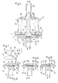
- the pressure valve V according to FIG. 1 has a two-part valve housing made of metal, consisting of an upper housing part 1 and a lower housing part 2, which thereby each other are connected that a flange 3 of the lower housing part 2 around a flange 4 of the upper housing part 1 is crumbled around.
- a rubber elastic Membrane 5 made of a fluorine elastomer or Nitrile butadiene elastomer with a reinforcing fabric Made of polyimide or polyamide and a hardness of about 70 shore clamped.
- the membrane 5 divides that Valve housing in an inlet space 6 and a low pressure space 7. It carries a valve closure plate 8 Metal opposite a sealing washer 9 made of rubber-elastic Material, preferably a fluorine elastomer, with a hardness of about 60 to 70 Shore and a thickness of about 1 mm.
- the sealing disk 9 has a circumferential, an approximately semicircular cross-sectional profile soft sealing lip 10 that plan with a hard Surface 11 of the valve closure plate 8 cooperates.
- the sealing disc 9 is in a flat circular cylindrical Deepening the bottom of the housing part 2 under Intermediate vulcanization of an adhesion promoter.
- inlet openings 12 for a pressure fluid is provided, which is indicated by flow arrows 13 is indicated.
- the inlet openings 12 are within one molded onto the outside of the bottom of the lower housing part 2 Connection piece 14.
- valve closure plate 8 On their through the sealing washer 9 and the bottom facing away from the lower housing part 2 formed valve seat On the side, the valve closure plate 8 has a projection 15, the middle aligned with each other Holes in the membrane 5 and a membrane plate 16 Metal is passed, the membrane 5 between Valve closure plate 8 and membrane plate 16 lies.
- the projection 15 On the circumference of the projection 15 is by axial Upset an edge section of the sealing disk 9 facing end face of the projection 15 a radial projecting flange 17 formed the membrane plate 16 and the membrane 5 between themselves and the valve closure plate 8 clamped.
- Coaxial on the ledge 15, i.e. is in the middle of the valve closure plate 8 perpendicular to this a hollow guide rod 18 in one piece formed with the valve closure plate 8.
- the Guide rod 18 is in with its free end portion the bore of one on the end wall 19 of the upper housing part 1 in one piece with this trained pipe socket 20 led.
- the pipe socket 20 has on the part of Low pressure room 7 an approximated to the outside tapering to the diameter of the guide rod 18 Opening 21 that the insertion of the guide rod 18 facilitated in the bore of the pipe socket 20.
- the guide rod 18 designed as a tube connects the side of the valve closure plate facing the valve seat 8 therefore with the pipe socket 20.
- the inner opening 23 forming an orifice Guide rod 18 from the sealing lip 10 of the sealing washer 9 surrounded.
- FIG. 2 shows a block diagram of an application example of the pressure valve V shown in Fig. 1.
- a pump 25 turns a tank 24 into a combustible one Fluid, e.g. Petrol, into the injection line 26 an internal combustion engine M working with injection pumped.
- the connecting piece 14 of the pressure valve V is with the injection line 26 and the pipe socket 20 with connected to the tank 24.
- sealing washer 9a formed as a ring and in a recess of the surface 11 of the valve closure plate 8 is vulcanized, so that its sealing lip 10 in this case as a valve seat serving bottom of the lower housing part 2 facing is.
- the face 29 of the sealing disk 9a The bottom of the lower housing part 2 is flat in this case and trained hard.
- annular Sealing disc 9b flat on both sides and instead its sealing lip facing the sealing disc 9b Surface 29 of the bottom of the lower housing part 2 with a circumferential annular sealing lip 10a is provided, which cooperates with the sealing washer 9b.
- the pressure valve V ' differs from 1 as follows:
- the guide rod 18a is solid and the sealing washer 9 in one cylindrical recess of the surface 11 of the valve closure plate 8 arranged or vulcanized.
- the area 29 of the bottom of the lower housing part 2 is a valve seat even and hard trained.
- the as an orifice acting outlet opening 23 is in the inner end of the Connection piece 14 formed.
- the inlet openings 12 are located radially outside the connecting piece 14.
- FIG. 7 shows a block diagram of an application example of the pressure valve V 'according to FIG. 6.
- the pipe socket 20 not with the tank 24, but with the suction pipe, not shown an internal combustion engine or the atmosphere and the Connection piece 14 connected to the tank 24. Further are the inlet openings 12 with the pressure side of the pump 25 or the injection line 26 connected.
- valve closure plate 8 differs 6 only in that the sealing washer 9a reversed, i.e. in a depression of the surface 29 vulcanized, ring-shaped and their the sealing opening 10 surrounding the exit opening 23 which in turn hard and flat surface 11 of the valve closure plate 8 is turned.
- sealing washer 9c flat on both sides and the its facing surface 29 of the bottom of the lower housing part 2 with a surrounding the exit opening 23 Sealing lip 10a is provided.
- the valve closure plate 8 is supported in all embodiments via an axial projection that is formed around its edge, on the opposite Bottom of the housing. This lead prevents the sealing lip 10, 10a from being completely axial is pressed into the sealing disk 9, 9a-9c.
- the Sealing lip 10, 10a therefore always causes alone on the side and in connection with the opposite one Surface the seal of the closed valve V, V '.
Landscapes
- Physics & Mathematics (AREA)
- Fluid Mechanics (AREA)
- General Physics & Mathematics (AREA)
- Engineering & Computer Science (AREA)
- Automation & Control Theory (AREA)
- Safety Valves (AREA)
- Check Valves (AREA)
- Fluid-Pressure Circuits (AREA)
- Magnetically Actuated Valves (AREA)
- Valves And Accessory Devices For Braking Systems (AREA)
- Control Of Fluid Pressure (AREA)
Claims (6)
- Vanne de régulation de pression (V, V') dotée d'un boítier de vanne (1, 2) qui présente un siège de vanne (29); une plaque (8) de fermeture de vanne; une membrane (5) en matériau de caoutchouc élastique, fixée dans le boítier de vanne (1, 2) et délimitant une chambre d'admission (6) et une chambre à basse pression (7) dans le boítier de vanne; un plateau de membrane (16) par l'intermédiaire duquel la membrane (5) est serrée contre la plaque (8) de fermeture de vanne ; un ressort de compression (22) dont la poussée agit d'une part sur le plateau de membrane (16) et d'autre part sur une paroi frontale (19) du boítier de vanne (1, 2), qui délimite la chambre à basse pression (7); d'une tige de guidage (18, 18a) fixée au milieu de la plaque (8) de fermeture de vanne et perpendiculaire à cette dernière; un dispositif (20) de guidage fixé au boítier, dans lequel la tige de guidage (18; 18a) est guidée axialement ; une plaque d'étanchéité (9; 9a à 9c) en un matériau de caoutchouc élastique, disposée entre la plaque (8) de fermeture de vanne et le siège de vanne (29), et un raccord tubulaire (20) réalisé sur la paroi du boítier de la chambre à basse pression (7), la force élastique du ressort étant réglée par enfoncement axial de la paroi frontale (19), caractérisée en ce que la tige de guidage (18; 18a) est réalisée d'un seul tenant avec la plaque (8) de fermeture de la vanne, en ce que le ressort de compression (22) repose directement contre la paroi frontale (19) et en ce que le raccord tubulaire (20) est réalisé sur la paroi frontale (19) et forme le dispositif de guidage.
- Vanne de régulation de pression selon la revendication 1, caractérisée en ce que le raccord tubulaire (20) est réalisé d'un seul tenant avec la paroi frontale (19).
- Vanne de régulation de pression selon la revendication 1 ou 2, caractérisée en ce que le raccord tubulaire (20) présente sur le côté de la chambre à basse pression (7) une ouverture (21) qui se rétrécit coniquement en direction de l'extérieur, jusqu'à sensiblement le diamètre de la tige de guidage (18; 18a).
- Vanne de régulation de pression selon l'une des revendications 1 à 3, caractérisée en ce que la tige de guidage (18) est configurée comme tube qui relie au raccord tubulaire (20) le côté de la plaque (8) de fermeture de la vanne qui est tourné vers le siège de vanne (29).
- Vanne de régulation de pression selon l'une des revendications 1 à 4, caractérisée en ce que sur son côté tourné vers la chambre intermédiaire (6) située entre la plaque (8) de fermeture de la vanne et le siège de vanne (29), la plaque d'étanchéité (9) présente une lèvre d'étanchéité (10) qui en déborde axialement et qui délimite une ouverture de sortie (23) de la vanne.
- Vanne de régulation de pression selon l'une des revendications 1 à 5, caractérisée en ce que la plaque d'étanchéité (9; 9a à 9c) est fixée par vulcanisation sur l'une des deux surfaces (11, 29) tournées l'une vers l'autre de la plaque (8) de fermeture de la vanne et du fond du boítier.
Applications Claiming Priority (2)
| Application Number | Priority Date | Filing Date | Title |
|---|---|---|---|
| DE19616512A DE19616512C1 (de) | 1996-04-25 | 1996-04-25 | Druckventil |
| DE19616512 | 1996-04-25 |
Publications (3)
| Publication Number | Publication Date |
|---|---|
| EP0803649A2 EP0803649A2 (fr) | 1997-10-29 |
| EP0803649A3 EP0803649A3 (fr) | 1997-11-05 |
| EP0803649B1 true EP0803649B1 (fr) | 2001-03-07 |
Family
ID=7792409
Family Applications (1)
| Application Number | Title | Priority Date | Filing Date |
|---|---|---|---|
| EP97105015A Expired - Lifetime EP0803649B1 (fr) | 1996-04-25 | 1997-03-25 | Vanne de régulation de pression |
Country Status (5)
| Country | Link |
|---|---|
| EP (1) | EP0803649B1 (fr) |
| AT (1) | ATE199579T1 (fr) |
| DE (2) | DE19616512C1 (fr) |
| ES (1) | ES2155952T3 (fr) |
| PT (1) | PT803649E (fr) |
Families Citing this family (3)
| Publication number | Priority date | Publication date | Assignee | Title |
|---|---|---|---|---|
| DE19739841C5 (de) * | 1997-09-11 | 2004-08-26 | Walter Schiffer | Druckregelventil |
| DE10323836B3 (de) * | 2003-05-23 | 2005-02-03 | Effbe Gmbh | Druckventil mit Dichtungsvorrichtung, insbesondere für die Kraftfahrzeugtechnik |
| CN103047067A (zh) * | 2011-10-11 | 2013-04-17 | 上海索菲玛汽车滤清器有限公司 | 燃油压力调节器 |
Family Cites Families (14)
| Publication number | Priority date | Publication date | Assignee | Title |
|---|---|---|---|---|
| DE2110142A1 (de) * | 1970-03-19 | 1971-10-07 | Fisker, Henry Juhl Jensen, Port Credit, Ontario (Kanada) | Unterdruckregelventil |
| US4204561A (en) * | 1977-09-08 | 1980-05-27 | Tom Mcguane Industries, Inc. | Fuel pressure regulator assembly |
| DE3006587A1 (de) * | 1980-02-22 | 1981-09-10 | Robert Bosch Gmbh, 7000 Stuttgart | Membrandruckregler |
| JPS5814448U (ja) * | 1981-07-20 | 1983-01-29 | 株式会社デンソー | 負圧制御弁 |
| DE3505625C2 (de) * | 1985-02-19 | 1994-06-01 | Bosch Gmbh Robert | Kraftstoff-Druckregelvorrichtung |
| US4903721A (en) * | 1985-04-03 | 1990-02-27 | Outboard Marine Corporation | Fuel pressure regulator |
| US4627463A (en) * | 1985-04-11 | 1986-12-09 | Tom Mcguane Industries, Inc. | Fuel pressure regulator |
| US4646700A (en) * | 1985-04-17 | 1987-03-03 | Walbro Corporation | Pressure regulator for liquid fuel system |
| DE3723359A1 (de) * | 1987-07-15 | 1989-01-26 | Brumme Kg Effbe Werk | Druckventil |
| US4741360A (en) * | 1987-09-14 | 1988-05-03 | Tom Mcguane Industries, Inc. | Fuel pressure regulator |
| JPH01138368A (ja) * | 1987-11-25 | 1989-05-31 | Aisin Seiki Co Ltd | 燃料圧力制御弁 |
| US5076320A (en) * | 1990-10-19 | 1991-12-31 | Siemens Automotive L.P. | Fuel rail mounted fuel pressure regulator |
| DE4119431C2 (de) * | 1991-06-13 | 1994-05-19 | Brumme Kg Effbe Werk | Druckregler |
| DE29515292U1 (de) * | 1995-09-23 | 1995-11-30 | ContiTech Elastomer-Beschichtungen GmbH, 37154 Northeim | Druckregler und Druckdämpfer für Flüssigkeitssysteme |
-
1996
- 1996-04-25 DE DE19616512A patent/DE19616512C1/de not_active Expired - Fee Related
-
1997
- 1997-03-25 ES ES97105015T patent/ES2155952T3/es not_active Expired - Lifetime
- 1997-03-25 DE DE59703087T patent/DE59703087D1/de not_active Expired - Fee Related
- 1997-03-25 PT PT97105015T patent/PT803649E/pt unknown
- 1997-03-25 EP EP97105015A patent/EP0803649B1/fr not_active Expired - Lifetime
- 1997-03-25 AT AT97105015T patent/ATE199579T1/de not_active IP Right Cessation
Also Published As
| Publication number | Publication date |
|---|---|
| ATE199579T1 (de) | 2001-03-15 |
| DE59703087D1 (de) | 2001-04-12 |
| DE19616512C1 (de) | 1997-09-11 |
| EP0803649A3 (fr) | 1997-11-05 |
| EP0803649A2 (fr) | 1997-10-29 |
| ES2155952T3 (es) | 2001-06-01 |
| PT803649E (pt) | 2001-06-29 |
Similar Documents
| Publication | Publication Date | Title |
|---|---|---|
| DE4022129C2 (fr) | ||
| DE19507321A1 (de) | Kraftstoff-Zuführeinrichtung für eine Brennkraftmaschine | |
| DE19649554A1 (de) | Membrandruckregelventilanordnung | |
| WO2005024232A1 (fr) | Pompe de refoulement d'un milieu de traitement postérieur, en particulier d'une solution urée-eau, pour moteurs diesel | |
| DE102007002841A1 (de) | Ventil zum Steuern eines gasförmigen Mediums | |
| EP0803649B1 (fr) | Vanne de régulation de pression | |
| DE10239407A1 (de) | Druckregelventil | |
| DE2710102A1 (de) | Durchflussteuerventil fuer eine abgasrueckfuehrvorrichtung mit abgasdrucksteuerung | |
| DE60311358T2 (de) | Membrananordnung mit festem Anschlag für Brennstoffdruckregler | |
| EP0518207B1 (fr) | Régulateur de pression | |
| DE102007004560A1 (de) | Ventil zum Steuern eines Mediums | |
| WO2009127477A1 (fr) | Pompe manuelle pour le pompage de carburant | |
| DE10355645A1 (de) | Brennstoffeinspritzsystem | |
| DE102020126241A1 (de) | Membrananordnung | |
| WO2020187673A1 (fr) | Dispositif de soupape | |
| EP0021057A1 (fr) | Vanne d'arrêt | |
| DE102009008817A1 (de) | Handpumpe zum Pumpen von Kraftstoff | |
| DE19739841C5 (de) | Druckregelventil | |
| DE10155176A1 (de) | Druckregelventil | |
| DE102018125927A1 (de) | Ventilbauteil zum Regeln oder Steuern eines Fluiddrucks | |
| DE102012202226A1 (de) | Kraftstoffpumpanordnung für ein Kraftfahrzeug | |
| DE2636490A1 (de) | Auslass-rueckschlagventil fuer eine kfz-kraftstoffpumpe | |
| DE19722061A1 (de) | Druckregelventil | |
| DE10306146A1 (de) | Niederdruckspeicher für eine Hochdruckkolbenpumpe | |
| DE112020001933T5 (de) | Membran und fluid-einrichtung |
Legal Events
| Date | Code | Title | Description |
|---|---|---|---|
| PUAI | Public reference made under article 153(3) epc to a published international application that has entered the european phase |
Free format text: ORIGINAL CODE: 0009012 |
|
| PUAL | Search report despatched |
Free format text: ORIGINAL CODE: 0009013 |
|
| AK | Designated contracting states |
Kind code of ref document: A2 Designated state(s): AT BE DE ES FR GB IT NL PT SE |
|
| AK | Designated contracting states |
Kind code of ref document: A3 Designated state(s): AT BE DE ES FR GB IT NL PT SE |
|
| 17P | Request for examination filed |
Effective date: 19971004 |
|
| GRAG | Despatch of communication of intention to grant |
Free format text: ORIGINAL CODE: EPIDOS AGRA |
|
| 17Q | First examination report despatched |
Effective date: 20000229 |
|
| GRAG | Despatch of communication of intention to grant |
Free format text: ORIGINAL CODE: EPIDOS AGRA |
|
| GRAH | Despatch of communication of intention to grant a patent |
Free format text: ORIGINAL CODE: EPIDOS IGRA |
|
| GRAH | Despatch of communication of intention to grant a patent |
Free format text: ORIGINAL CODE: EPIDOS IGRA |
|
| GRAA | (expected) grant |
Free format text: ORIGINAL CODE: 0009210 |
|
| AK | Designated contracting states |
Kind code of ref document: B1 Designated state(s): AT BE DE ES FR GB IT NL PT SE |
|
| REF | Corresponds to: |
Ref document number: 199579 Country of ref document: AT Date of ref document: 20010315 Kind code of ref document: T |
|
| RIN1 | Information on inventor provided before grant (corrected) |
Inventor name: SCHREPFER, JUERGEN Inventor name: SCHIFFER, WALTER |
|
| ITF | It: translation for a ep patent filed | ||
| GBT | Gb: translation of ep patent filed (gb section 77(6)(a)/1977) |
Effective date: 20010307 |
|
| REF | Corresponds to: |
Ref document number: 59703087 Country of ref document: DE Date of ref document: 20010412 |
|
| REG | Reference to a national code |
Ref country code: ES Ref legal event code: FG2A Ref document number: 2155952 Country of ref document: ES Kind code of ref document: T3 |
|
| REG | Reference to a national code |
Ref country code: PT Ref legal event code: SC4A Free format text: AVAILABILITY OF NATIONAL TRANSLATION Effective date: 20010319 |
|
| ET | Fr: translation filed | ||
| REG | Reference to a national code |
Ref country code: GB Ref legal event code: IF02 |
|
| PLBE | No opposition filed within time limit |
Free format text: ORIGINAL CODE: 0009261 |
|
| STAA | Information on the status of an ep patent application or granted ep patent |
Free format text: STATUS: NO OPPOSITION FILED WITHIN TIME LIMIT |
|
| 26N | No opposition filed | ||
| PGFP | Annual fee paid to national office [announced via postgrant information from national office to epo] |
Ref country code: SE Payment date: 20030306 Year of fee payment: 7 |
|
| PGFP | Annual fee paid to national office [announced via postgrant information from national office to epo] |
Ref country code: AT Payment date: 20030312 Year of fee payment: 7 |
|
| PGFP | Annual fee paid to national office [announced via postgrant information from national office to epo] |
Ref country code: PT Payment date: 20030327 Year of fee payment: 7 Ref country code: NL Payment date: 20030327 Year of fee payment: 7 |
|
| PGFP | Annual fee paid to national office [announced via postgrant information from national office to epo] |
Ref country code: BE Payment date: 20030516 Year of fee payment: 7 |
|
| PG25 | Lapsed in a contracting state [announced via postgrant information from national office to epo] |
Ref country code: AT Free format text: LAPSE BECAUSE OF NON-PAYMENT OF DUE FEES Effective date: 20040325 |
|
| PG25 | Lapsed in a contracting state [announced via postgrant information from national office to epo] |
Ref country code: SE Free format text: LAPSE BECAUSE OF NON-PAYMENT OF DUE FEES Effective date: 20040326 |
|
| PG25 | Lapsed in a contracting state [announced via postgrant information from national office to epo] |
Ref country code: BE Free format text: LAPSE BECAUSE OF NON-PAYMENT OF DUE FEES Effective date: 20040331 |
|
| BERE | Be: lapsed |
Owner name: EFFBE-WERK FRITZ *BRUMME G.M.B.H. Effective date: 20040331 |
|
| PG25 | Lapsed in a contracting state [announced via postgrant information from national office to epo] |
Ref country code: NL Free format text: LAPSE BECAUSE OF NON-PAYMENT OF DUE FEES Effective date: 20041001 |
|
| PG25 | Lapsed in a contracting state [announced via postgrant information from national office to epo] |
Ref country code: PT Free format text: LAPSE BECAUSE OF NON-PAYMENT OF DUE FEES Effective date: 20041015 |
|
| EUG | Se: european patent has lapsed | ||
| REG | Reference to a national code |
Ref country code: PT Ref legal event code: MM4A Free format text: LAPSE DUE TO NON-PAYMENT OF FEES Effective date: 20040930 |
|
| NLV4 | Nl: lapsed or anulled due to non-payment of the annual fee |
Effective date: 20041001 |
|
| PG25 | Lapsed in a contracting state [announced via postgrant information from national office to epo] |
Ref country code: IT Free format text: LAPSE BECAUSE OF NON-PAYMENT OF DUE FEES Effective date: 20050325 |
|
| PGFP | Annual fee paid to national office [announced via postgrant information from national office to epo] |
Ref country code: FR Payment date: 20060313 Year of fee payment: 10 |
|
| PGFP | Annual fee paid to national office [announced via postgrant information from national office to epo] |
Ref country code: DE Payment date: 20060314 Year of fee payment: 10 |
|
| PGFP | Annual fee paid to national office [announced via postgrant information from national office to epo] |
Ref country code: ES Payment date: 20060329 Year of fee payment: 10 |
|
| GBPC | Gb: european patent ceased through non-payment of renewal fee |
Effective date: 20070325 |
|
| REG | Reference to a national code |
Ref country code: FR Ref legal event code: ST Effective date: 20071130 |
|
| PG25 | Lapsed in a contracting state [announced via postgrant information from national office to epo] |
Ref country code: DE Free format text: LAPSE BECAUSE OF NON-PAYMENT OF DUE FEES Effective date: 20071002 |
|
| PG25 | Lapsed in a contracting state [announced via postgrant information from national office to epo] |
Ref country code: GB Free format text: LAPSE BECAUSE OF NON-PAYMENT OF DUE FEES Effective date: 20070325 |
|
| REG | Reference to a national code |
Ref country code: ES Ref legal event code: FD2A Effective date: 20070326 |
|
| PG25 | Lapsed in a contracting state [announced via postgrant information from national office to epo] |
Ref country code: FR Free format text: LAPSE BECAUSE OF NON-PAYMENT OF DUE FEES Effective date: 20070402 Ref country code: ES Free format text: LAPSE BECAUSE OF NON-PAYMENT OF DUE FEES Effective date: 20070326 |
|
| PGFP | Annual fee paid to national office [announced via postgrant information from national office to epo] |
Ref country code: GB Payment date: 20060322 Year of fee payment: 10 |