EP0803609A2 - Method for accurately placing an insert in concrete, apparatus for performing said method , and railway track obtained through the method - Google Patents
Method for accurately placing an insert in concrete, apparatus for performing said method , and railway track obtained through the method Download PDFInfo
- Publication number
- EP0803609A2 EP0803609A2 EP97400910A EP97400910A EP0803609A2 EP 0803609 A2 EP0803609 A2 EP 0803609A2 EP 97400910 A EP97400910 A EP 97400910A EP 97400910 A EP97400910 A EP 97400910A EP 0803609 A2 EP0803609 A2 EP 0803609A2
- Authority
- EP
- European Patent Office
- Prior art keywords
- concrete
- saddle
- insert
- given
- une
- Prior art date
- Legal status (The legal status is an assumption and is not a legal conclusion. Google has not performed a legal analysis and makes no representation as to the accuracy of the status listed.)
- Granted
Links
Images

Classifications
-
- E—FIXED CONSTRUCTIONS
- E01—CONSTRUCTION OF ROADS, RAILWAYS, OR BRIDGES
- E01B—PERMANENT WAY; PERMANENT-WAY TOOLS; MACHINES FOR MAKING RAILWAYS OF ALL KINDS
- E01B3/00—Transverse or longitudinal sleepers; Other means resting directly on the ballastway for supporting rails
- E01B3/28—Transverse or longitudinal sleepers; Other means resting directly on the ballastway for supporting rails made from concrete or from natural or artificial stone
- E01B3/38—Longitudinal sleepers; Longitudinal sleepers integral or combined with tie-rods; Combined longitudinal and transverse sleepers; Layers of concrete supporting both rails
-
- B—PERFORMING OPERATIONS; TRANSPORTING
- B28—WORKING CEMENT, CLAY, OR STONE
- B28B—SHAPING CLAY OR OTHER CERAMIC COMPOSITIONS; SHAPING SLAG; SHAPING MIXTURES CONTAINING CEMENTITIOUS MATERIAL, e.g. PLASTER
- B28B23/00—Arrangements specially adapted for the production of shaped articles with elements wholly or partly embedded in the moulding material; Production of reinforced objects
- B28B23/005—Arrangements specially adapted for the production of shaped articles with elements wholly or partly embedded in the moulding material; Production of reinforced objects with anchoring or fastening elements for the shaped articles
-
- B—PERFORMING OPERATIONS; TRANSPORTING
- B28—WORKING CEMENT, CLAY, OR STONE
- B28B—SHAPING CLAY OR OTHER CERAMIC COMPOSITIONS; SHAPING SLAG; SHAPING MIXTURES CONTAINING CEMENTITIOUS MATERIAL, e.g. PLASTER
- B28B23/00—Arrangements specially adapted for the production of shaped articles with elements wholly or partly embedded in the moulding material; Production of reinforced objects
- B28B23/0062—Arrangements specially adapted for the production of shaped articles with elements wholly or partly embedded in the moulding material; Production of reinforced objects forcing the elements into the cast material, e.g. hooks into cast concrete
-
- E—FIXED CONSTRUCTIONS
- E01—CONSTRUCTION OF ROADS, RAILWAYS, OR BRIDGES
- E01B—PERMANENT WAY; PERMANENT-WAY TOOLS; MACHINES FOR MAKING RAILWAYS OF ALL KINDS
- E01B29/00—Laying, rebuilding, or taking-up tracks; Tools or machines therefor
- E01B29/32—Installing or removing track components, not covered by the preceding groups, e.g. sole-plates, rail anchors
-
- E—FIXED CONSTRUCTIONS
- E01—CONSTRUCTION OF ROADS, RAILWAYS, OR BRIDGES
- E01B—PERMANENT WAY; PERMANENT-WAY TOOLS; MACHINES FOR MAKING RAILWAYS OF ALL KINDS
- E01B31/00—Working rails, sleepers, baseplates, or the like, in or on the line; Machines, tools, or auxiliary devices specially designed therefor
- E01B31/20—Working or treating non-metal sleepers in or on the line, e.g. marking, creosoting
- E01B31/26—Inserting or removing inserts or fillings for holes in sleepers, e.g. plugs, sleeves
-
- E—FIXED CONSTRUCTIONS
- E01—CONSTRUCTION OF ROADS, RAILWAYS, OR BRIDGES
- E01B—PERMANENT WAY; PERMANENT-WAY TOOLS; MACHINES FOR MAKING RAILWAYS OF ALL KINDS
- E01B9/00—Fastening rails on sleepers, or the like
- E01B9/02—Fastening rails, tie-plates, or chairs directly on sleepers or foundations; Means therefor
- E01B9/04—Fastening on wooden or concrete sleepers or on masonry without clamp members
- E01B9/14—Plugs, sleeves, thread linings, or other inserts for holes in sleepers
- E01B9/18—Plugs, sleeves, thread linings, or other inserts for holes in sleepers for concrete sleepers
Definitions
- the invention relates to civil engineering, in particular the construction of railway tracks.
- this method is particularly advantageous for inserting, in a concrete slab, saddles supporting railway rails. It is also applicable in all cases where one inserts in concrete, at a given position, with an accuracy of the order of a millimeter, an insert which comprises at least one cavity which must be filled with concrete for the 'insert withstands significant efforts.
- the object of the invention is to provide a method for making a railway track, without sleepers, at a lower cost than this known method.
- the method thus characterized makes it possible to use inserts comprising relatively deep cavities without there being a risk of improper filling. Therefore, it guarantees an anchorage very resistant to constraints. This property is particularly advantageous for inserts supporting railway rails.
- the method thus characterized makes it possible to significantly reduce the cost of making a railway track, since there is no longer a step consisting in fixing spacer gauges, and in verifying its position before pouring concrete.
- the precision obtained on the position of each saddle is sufficient to obtain the desired precision for the spacing between the two rails of a track, and for the position of the running surface.
- the fact of depositing a concrete slab before laying the rails, and not after, makes it possible to use a conventional machine with sliding formwork which makes it possible to pour a concrete slab with very little labor.
- the method according to the invention is characterized in that, for driving a saddle into a concrete slab, by vibrating this saddle, until it reaches a given position, with a given tolerance, it consists in slaving the position of the saddle to a predetermined position setpoint, along three axes orthogonal to each other, or another equivalent reference.
- the process thus characterized makes it possible to automate the sinking of the saddle, while providing excellent position accuracy.
- the invention also relates to a device for implementing the method according to the invention.
- the invention relates to a railway track obtained by the method according to the invention.
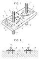
- the plate 3 has a generally rectangular, flat and horizontal shape, comprising: a vertical border 11 over its entire periphery, four reinforcing ribs, and two bosses 5 and 10 having vertical walls slightly inclined. These bosses 5 and 10 are provided in particular to collaborate with parts, not shown, which will be used for the subsequent fixing of a rail. In the use made of it here, the bosses 5 and 10 also have the function of providing a free space allowing the ascent of a volume of concrete equal to the volume of the concrete displaced by the sealing rods 6 and 9 when the saddle is embedded in concrete. On the other hand, the saddles 1 and 1 ′ have a plurality of orifices 7, 12 allowing the air to escape when the concrete fills the bowl formed by the plate 3, its edge 11, and the bosses 5 and 10.
- Each stud is fixed to the sole by force fitting, or by welding.
- the threaded part of the stud can be protected during all the saddle insertion operations, by means of a plastic sleeve screwed onto this threaded part.
- the method according to the invention is applicable not only to this type of insert but also to any other type of insert that can be sealed in concrete.
- FIG. 2 shows in section an example of a railway track produced using this type of saddle and applying the method according to the invention.
- This figure 2 shows two rails, 12 and 14, fixed respectively on two saddles 13 and 15, by nuts and parts inserted in a conventional manner between each nut and the rail.
- the altitude of each of the rails 12 and 14 is determined on the one hand by the altitude of the surface of the slab 16 which is manufactured with a given precision, of the order of a few millimeters, and on the other hand is a function of the depression of the saddle in the concrete of the slab 16, this depression being adjusted so that the running surface has a given position, with an accuracy of the order of a millimeter.
- the spacing between the rails 12 and 14 is determined by the distance separating the two saddles when they are sealed. There are no spacer gauges between these rails, nor a priori an adjustment shim.
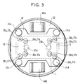
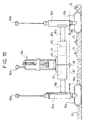
- Figures 3 and 4 respectively represent a top view and a sectional view of the main part of an example of an insertion device specially adapted for the insertion of the type of saddle shown in Figure 1.
- This example includes a base consisting of a sheet 30 intended to be placed directly on the surface 25 of a concrete slab 31 in which must be inserted a saddle.
- This concrete is fresh, smooth, and has a firm consistency.
- This sheet 30 has a circular opening on which is welded a vertical tube 21 allowing the passage of a movable part.
- FIG. 3 does not represent the vibration device 35, neither the parts 33a and 33b, nor the stirrup 39.
- FIG. 4 does not represent the hydraulic pipes supplying the clamps and the vibration device.
- the vibration device 35 comprises one or more vibrators, each vibrator consisting for example of a hydraulic motor having an unbalance.
- the whole of the vibration device 35 vibrates while driving in its movement the plate 32 which has a certain freedom thanks to the elastic blocks 24a to 24d.
- the clamps 23a and 23b transmit the vibrations to the anchor rods 9 and 6. Under the action of these vibrations, the concrete is much more fluid in the vicinity of the anchor rods, which makes it possible to drive them in with less force and to obtain a much more precise positioning.
- FIG. 6 illustrates a first step during which the saddle 1 is placed manually or automatically, inside the receptacle 28, by inserting the threaded rods of the studs in the hydraulic clamps 23a and 23b (The latter is not shown).
- the cylinders 44 and 41 are retracted, which leaves space between the tube 21 and the receptacle 28 to access the interior of the latter.
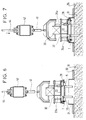
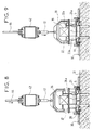
- FIG. 7 illustrates a second step during which the saddle 1 is quickly depressed.
- the vibration device 35 is activated with an amplitude and a frequency adapted to facilitate penetration of the saddle 1 in the concrete slab 31, making the concrete more fluid in the vicinity of the anchor rods.
- the rubber blocks 24a, etc ... allow the plate 32 to move slightly in all directions, relative to the plate 22.
- the jack 44 is actuated to push the saddle 1 to a position close to the position final planned, to within a few millimeters.
- the jack 44 moves: the sliding part 42, the arms 40a and 40b (not shown), the support plate 22, and the receptacle 28 which are associated with it.
- the saddle 1 is therefore pushed into the liquefied concrete by vibrations.
- the receptacle 28 is lowered until it is in the vicinity of the surface 25 of the concrete slab. It should be noted that the guide fingers 26a, etc., are still in the raised position and are not in contact with the saddle 1.
- FIG. 8 illustrates a third step of inserting the saddle 1, consisting of completing the insertion at a lower speed, adapted to precise positioning, up to the final depth provided for the saddle.
- the jack 44 is activated again, but with a lower speed.
- the vibration device 35 is activated, but the amplitude and frequency of the vibrations are adapted for precise positioning of the saddle 1.
- the receptacle 28 and the plate 30, which are almost contiguous, confine the concrete and force it to rise in the bosses 5 and 10.
- the vibration device 35 and the jack 44 are stopped.
- FIG. 9 illustrates a fourth step during which the vibration device 35 is stopped.
- the cylinder 41 is activated in turn. He lowers the stirrup 39 which is integral with the part 33a (partially shown) and with the part 33b (not shown), these parts 33a and 33b supporting the fingers 26a, etc.
- the stirrup 39 lowers until to abut on the plate 32.
- the ends of the fingers 26a, etc ... then come into contact with the flat part of the saddle 1. If the saddle 1 is not perfectly positioned in the horizontal plane, the fingers rub on the vertical walls of the bosses 5 and 10 of the saddle 1 and cause a slight displacement of the saddle 1, in the horizontal plane, to reposition the saddle 1 in a position well defined by the eight fingers.
- the clamps 23a, etc ... are kept tight, and the fingers 26a, etc ... are kept in this position until the increase in the viscosity of the concrete is sufficient to prevent any displacement of the saddle during the raising of the fingers.
- the hydraulic clamps 23a and 23b are then controlled to release the saddle studs 1. Then the jack 41 is activated in the opposite direction to raise the fingers 26a, etc ... Then the jack 44 is activated in the opposite direction to reassemble the entire mobile part of the insertion device.
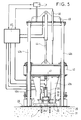
- Figures 10 and 11 respectively represent two front views of a mobile machine allowing the insertion of two saddles simultaneously.
- the machine is in a state to move it and prepare the insertion of a saddle.
- the machine is inserting a saddle into a fresh concrete slab 62.
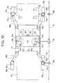
- Figure 12 shows a top view. In these figures, the machine has already inserted saddles 70 to 76 in a concrete slab 62.
- This exemplary embodiment comprises a mobile platform 52 supporting two insertion devices 51a and 51b, identical to each other and which can be similar to the insertion device shown in FIGS. 3 to 5, and which has been described previously. They notably include position sensors 64a, respectively 64b, analogous to the sensor CP; and control units UC1, respectively UC2, analogous to the control unit UC.
- the devices 51a and 51b are mounted on a carriage 63 which is integral with the platform 52 and movable relative to the latter along two horizontal axes, orthogonal to one another.
- a set of jacks not shown, makes it possible to lower the devices 51a and 51b until their bases (sheet 30) rest on the surface of the concrete slab 62.
- the devices 51a and 51b pass through the carriage 63 through openings 61a and 61b respectively, and pass through the platform 52 through an opening 62.
- the platform 52 is mounted on four tracks 53a, 53b, 53c, 53d, by means of four horizontal articulated arms 55a, 55b, 55c, 55d, making it possible to adjust the spacing between the tracks, and via four vertical legs 57a, 57b, 57c, 57d, allowing the height of each arm 55a, 55b, 55c, 55d to be adjusted independently, respectively with respect to the tracks 53a, 53b, 53c, 53d, resting on the ground.
- the position of the platform 52 is controlled according to three orthogonal axes, by means of a control unit UC3, so that it follows the profile provided for the raceway, consequently it follows the surface of the slab 62.
- the legs 54a and 54b respectively support sensors 58a and 58b which follow a guide 57 parallel to the profile along the rails to be installed.
- This guide 57 is marked, in order to control the position of the platform 52 along two horizontal axes with reference to this guide 57.
- the platform 52 spans the concrete slab 62 and moves along this slab 62 by means of motors actuating the tracks 53a, ..., 53d.
- the legs 54a and 54b respectively carry sensors 60a and 60b making it possible to determine the respective altitudes of the arms 55a and 55b relative to a laser plane, taking into account the height adjustment of these arms relative to the legs 54a and 54b. Knowing these altitudes makes it possible to control these altitudes at predetermined set values so that the platform 52 follows the profile of the track.
- the concrete used has a firm consistency.
- the slab 62 was freshly poured, vibrated in place, rectified, and smoothed, by a conventional machine with sliding forms, such as those used for making concrete pavements, for motorways. It gives the surface of the slab a position deducted from the position provided for the running surface of the track, with an accuracy of the order of 2 millimeters, thanks to conventional position controls.
- the saddle inserts, 51a and 51b are spaced apart by an interval corresponding to the interval provided for the rails.
- the mobile carriage 63 moves them together and makes it possible to refine the insertion position, with an accuracy of the order of a millimeter along two horizontal axes, even better than that provided by the platform 52.
- the mobile carriage 63 carries a position sensor 59 which makes it possible to control the position of the carriage 63 along two horizontal axes, by referring to the position of the same guide 57, but with a finer tolerance than the tolerance on the position of the platform 52.
- the carriage is moved by two motors, not shown, controlled by a control unit UC4, according to the measurements made by the sensor 59 and according to the position provided for the two saddles to be inserted.
- the slaving of the insertion devices 51a and 51b along a vertical axis, by the control units UC1 and UC2, makes it possible to insert each saddle with an altitude precision of the order of a millimeter, even better than the precision obtained on the altitude of the surface of the concrete layer 62.
- Position control devices referring to the position of a guide and the position of a laser plane, are conventional devices. However, other known types of position control device could also be used to obtain a precise position of each saddle.
- the insertion devices 51a and 51b could be mounted directly on the machine used to pour in place the slab of concrete 62, instead of the platform 52.
- the production of this machine will not be described since it is analogous to the production of a machine conventionally used for making concrete highways.
Landscapes
- Engineering & Computer Science (AREA)
- Architecture (AREA)
- Civil Engineering (AREA)
- Structural Engineering (AREA)
- Mechanical Engineering (AREA)
- Ceramic Engineering (AREA)
- Chemical & Material Sciences (AREA)
- Manufacturing & Machinery (AREA)
- On-Site Construction Work That Accompanies The Preparation And Application Of Concrete (AREA)
- Conveying And Assembling Of Building Elements In Situ (AREA)
- Machines For Laying And Maintaining Railways (AREA)
- Devices For Post-Treatments, Processing, Supply, Discharge, And Other Processes (AREA)
- Manufacturing Of Tubular Articles Or Embedded Moulded Articles (AREA)
Abstract
Description
L'invention concerne le génie civil, en particulier la construction des voies de chemin de fer. En effet, ce procédé est particulièrement avantageux pour insérer, dans une dalle de béton, des selles supportant des rails de chemin de fer. Il est applicable aussi dans tous les cas où on scelle dans du béton, à une position donnée, avec une précision de l'ordre d'un millimètre, un insert qui comporte au moins une cavité qui doit être remplie par du béton pour que l'insert résiste à des efforts importants.The invention relates to civil engineering, in particular the construction of railway tracks. In fact, this method is particularly advantageous for inserting, in a concrete slab, saddles supporting railway rails. It is also applicable in all cases where one inserts in concrete, at a given position, with an accuracy of the order of a millimeter, an insert which comprises at least one cavity which must be filled with concrete for the 'insert withstands significant efforts.
On connaît, par le document EP 0 117 323 un procédé pour mettre en place, avec précision par rapport à une ligne de référence, des barres de liaison entre deux dalles de béton, pour réaliser une autoroute ou une piste d'aviation. Ces barres sont placées horizontalement, et perpendiculairement au plan du joint de dilatation . Ce procédé consiste à :
- couler une dalle de béton continue et lisser sa surface ;
- puis, pendant que ce béton est frais, enfoncer chaque barre de liaison dans le béton frais, en faisant vibrer la barre pour liquéfier le béton autour de cette barre pendant son déplacement, jusqu'à qu'elle atteigne une position donnée : les vibrations pendant le déplacement permettent un positionnement précis par rapport à une ligne de référence ;
- puis mettre en place un joint de dilatation qui coupe la dalle continue et la sépare en deux dalles qui restent reliées par les barres de liaisons.
- pour a continuous concrete slab and smooth its surface;
- then, while this concrete is fresh, push each link bar into the fresh concrete, vibrating the bar to liquefy the concrete around this bar during its movement, until it reaches a given position: vibrations during the displacement allow precise positioning relative to a reference line;
- then install an expansion joint which cuts the continuous slab and separates it into two slabs which remain connected by the connecting bars.
On connaît divers procédés pour réaliser une voie de chemin de fer. Les voies les plus courantes sont supportées par des traverses posées sur ballast. Cependant on réalise des voies sans traverses pour des applications particulières, en particulier pour les voies de tramway dans des zones de circulation routière. Ces voies doivent être encastrées dans la chaussée, et demandent donc des terrassements dits de décaissement. On minimise la profondeur du décaissement, pour réduire les coûts et réduire les désagréments occasionnés aux riverains et aux usagers des chaussées routières. Pour cela, on réalise des voies comportant une dalle de béton au lieu des traverses classiques. Les rails reposent sur la dalle de béton par l'intermédiaire de pièces métalliques appelées selles et de semelles en caoutchouc. Les selles sont fixées à la dalle de béton, pour transmettre les efforts exercés par le passage d'un tramway sur cette voie.Various methods are known for making a railway track. The most common tracks are supported by sleepers placed on ballast. However, tracks without crosspieces are produced for specific applications, in particular for tram tracks in areas of road traffic. These tracks must be embedded in the roadway, and therefore require so-called disbursement earthworks. The depth of the disbursement is minimized to reduce costs and reduce the inconvenience caused to residents and road users. For this, we realize tracks with a concrete slab instead of conventional sleepers. The rails rest on the concrete slab by means of metal parts called saddles and rubber footings. The saddles are fixed to the concrete slab, to transmit the forces exerted by the passage of a tram on this track.
Un procédé connu pour réaliser une telle voie consiste à :
- solidariser deux rails en fixant manuellement des gabarits entretoises, réglables en altitude au moyen de vérins, pour définir l'écartement des rails et leurs altitudes respectives ;
- fixer manuellement des selles à intervalles réguliers sous chaque rail, entre les gabarits ; chaque selle comportant, sur une face, des goujons filetés permettant de fixer cette selle à un rail, et comportant, sur une autre face, des dispositifs d'ancrage aptes à être scellés dans du béton ;
- ajuster ces gabarits pour que le plan de roulement soit à l'altitude prévue et présente les pentes prévues ;
- poser des coffrages latéraux recyclables ;
- couler du béton sous les rails et le talocher, de telle sorte que les dispositifs d'ancrage des selles soient recouverts et noyés dans la dalle de béton, et que celle-ci présente une surface plane située juste en dessous des rails.
- securing two rails by manually fixing spacer templates, adjustable in height by means of jacks, to define the spacing of the rails and their respective altitudes;
- manually attach saddles at regular intervals under each rail, between the templates; each saddle comprising, on one side, threaded studs making it possible to fix this saddle to a rail, and comprising, on another side, anchoring devices capable of being sealed in concrete;
- adjust these gauges so that the running surface is at the planned altitude and presents the planned slopes;
- install recyclable side forms;
- pour concrete under the rails and float, so that the saddle anchors are covered and embedded in the concrete slab, and that it has a flat surface located just below the rails.
Ce procédé nécessite un grand soin pour obtenir un positionnement précis des rails par les gabarits, et il nécessite du temps pour le montage des gabarits entretoises et pour la mise en place du béton. Il est donc coûteux en main d'oeuvre. N'étant pas de nature industrielle, il laisse une grande part à l'initiative et au savoir-faire du personnel.This process requires great care to obtain precise positioning of the rails by the templates, and it requires time for the mounting of the spacer templates and for the placement of the concrete. It is therefore costly in labor. Not being of an industrial nature, it leaves much to the initiative and know-how of the staff.
Le but de l'invention est de proposer un procédé permettant de réaliser une voie de chemin de fer, sans traverses, à un coût moindre que ce procédé connu.The object of the invention is to provide a method for making a railway track, without sleepers, at a lower cost than this known method.
L'objet de l'invention est un procédé pour mettre en place avec précision un insert dans du béton, cet insert pouvant comporter une ou plusieurs cavités à remplir par du béton, consistant à :
- préparer un béton ayant une consistance ferme ;
- mettre en place ce béton, rectifier et lisser sa surface pendant qu'il est frais, pour donner à sa surface une position donnée, avec une tolérance donnée ;
- puis, pendant que ce béton est frais, déplacer l'insert dans ce béton, en faisant vibrer le béton autour de cet insert pendant son déplacement, jusqu'à qu'il atteigne une position donnée, avec une tolérance donnée ;
- prepare concrete with a firm consistency;
- place this concrete, rectify and smooth its surface while it is cool, to give its surface a given position, with a given tolerance;
- then, while this concrete is fresh, move the insert into this concrete, vibrating the concrete around this insert during its movement, until it reaches a given position, with a given tolerance;
Le procédé ainsi caractérisé permet d'utliser des inserts comportant des cavités relativement profondes sans qu'il y ait un risque de mauvais remplissage. Par conséquent, il garantit un ancrage trés résistant aux contraintes. Cette propriété est particulièrement avantageuse pour des inserts supportant des rails de chemin de fer.The method thus characterized makes it possible to use inserts comprising relatively deep cavities without there being a risk of improper filling. Therefore, it guarantees an anchorage very resistant to constraints. This property is particularly advantageous for inserts supporting railway rails.
Le procédé ainsi caractérisé procure en outre une grande précision grâce à la collaboration des trois caractéristiques ci-dessous :
- Le fait de faire vibrer le béton permet de le liquéfier momentanément au voisinage du point d'application des vibrations, autorisant ainsi un enfoncement aisé, un bon enrobage des parties noyées de l'insert, et de facto un bon scellement. Il est à noter que les vibrations peuvent être appliquées par l'intermédiaire de l'insert ou d'un autre dispositif indépendant de l'insert, et placé dans le béton, au voisinage de l'insert.
- Le fait que le béton soit mis en place en premier, qu'il soit lissé, et rectifié pour que sa surface ait une position relativement précise a pour effet qu'en enfonçant l'insert à une profondeur nominale (telle que le dispositif d'ancrage de l'insert ne sera ni trop ni insuffisamment recouvert par le béton), on place l'insert à une position qui est très proche de la position souhaitée. Il suffit d'une petite modification de l'enfoncement pour rattraper une éventuelle erreur de position de la surface du béton. La petitesse de cette modification autorise un ajustement très précis.
- L'insert conserve cette position avec cette précision pendant toute la durée de prise du béton parce que celui-ci retrouve rapidement, après l'arrêt des vibrations, une consistance ferme qui évite un déplacement du béton ou de l'insert sous l'action de leur poids.
- The fact of vibrating the concrete makes it possible to temporarily liquefy it in the vicinity of the point of application of the vibrations, thus allowing easy sinking, good coating of the drowned parts of the insert, and de facto good sealing. It should be noted that the vibrations can be applied via the insert or another device independent of the insert, and placed in the concrete, in the vicinity of the insert.
- The fact that the concrete is placed first, that it is smoothed, and rectified so that its surface has a relatively precise position has the effect that by driving the insert to a nominal depth (such as the anchoring of the insert will be neither too much nor insufficiently covered by concrete), the insert is placed at a position which is very close to the desired position. It only takes a small change in the penetration to make up for a possible error in the position of the concrete surface. The smallness of this modification allows a very precise adjustment.
- The insert maintains this position with this precision throughout the setting time of the concrete because it quickly regains, after the vibrations stop, a firm consistency which prevents displacement of the concrete or the insert under the action of their weight.
Lorsqu'il est appliqué à la réalisation d'une voie de chemin de fer comportant des rails supportées par des selles munies de dispositifs d'ancrage susceptibles d'être scellés dans du béton, le procédé selon l'invention est caractérisé en ce qu'il consiste en outre à :
- mettre le béton sous la forme d'une dalle ayant une surface unie dont la position est déduite de la position prévue pour le plan de roulement de la voie ;
- puis, pendant que le béton est frais, enfoncer chaque selle dans la dalle de béton, en faisant vibrer le béton autour de cette selle, jusqu'à ce qu'elle atteigne une position donnée, avec une tolérance donnée.
- putting the concrete in the form of a slab having a smooth surface, the position of which is deduced from the position provided for the running surface of the track;
- then, while the concrete is fresh, push each saddle into the concrete slab, vibrating the concrete around this saddle, until it reaches a given position, with a given tolerance.
Le procédé ainsi caractérisé permet de réduire notablement le coût de réalisation d'une voie de chemin de fer, puisqu'il n'y a plus d'étape consistant à fixer des gabarits entretoises, et à vérifier sa position avant de couler du béton. La précision obtenue sur la position de chaque selle est suffisante pour obtenir la précision souhaitée pour l'écartement entre les deux rails d'une voie, et pour la position du plan de roulement. En outre, le fait de déposer une dalle de béton avant de poser les rails, et non après, permet d'utiliser une machine classique à coffrages glissants qui permet de couler une dalle de béton avec très peu de main d'oeuvre.The method thus characterized makes it possible to significantly reduce the cost of making a railway track, since there is no longer a step consisting in fixing spacer gauges, and in verifying its position before pouring concrete. The precision obtained on the position of each saddle is sufficient to obtain the desired precision for the spacing between the two rails of a track, and for the position of the running surface. In addition, the fact of depositing a concrete slab before laying the rails, and not after, makes it possible to use a conventional machine with sliding formwork which makes it possible to pour a concrete slab with very little labor.
Selon un mode de mise en oeuvre préférentiel, le procédé selon l'invention est caractérisé en ce que, pour enfoncer une selle dans une dalle de béton, en faisant vibrer cette selle, jusqu'à ce qu'elle atteigne une position donnée, avec une tolérance donnée, il consiste à asservir la position de la selle à une consigne de position prédéterminée, selon trois axes orthogonaux entre eux, ou un autre repère équivalent.According to a preferred embodiment, the method according to the invention is characterized in that, for driving a saddle into a concrete slab, by vibrating this saddle, until it reaches a given position, with a given tolerance, it consists in slaving the position of the saddle to a predetermined position setpoint, along three axes orthogonal to each other, or another equivalent reference.
Le procédé ainsi caractérisé permet d'automatiser l'enfoncement de la selle, tout en procurant une excellente précision de position.The process thus characterized makes it possible to automate the sinking of the saddle, while providing excellent position accuracy.
Selon un mode de mise en oeuvre préférentiel, le procédé selon l'invention est caractérisé en ce que, pour enfoncer une selle jusqu'à ce qu'elle atteigne une position donnée, avec une position donnée, il consiste :
- dans une première étape, à enfoncer la selle avec une première vitesse fixée, en laissant une certaine liberté à la selle dans un plan horizontal, et en faisant vibrer cette selle avec une fréquence et une amplitude de vibration adaptées à un enfoncement rapide, jusqu'à ce qu'elle atteigne une position voisine de la consigne ;
- puis, dans une seconde étape, à positionner la selle avec une seconde vitesse fixée, inférieure à la première, en faisant vibrer cette selle avec une fréquence et une amplitude de vibration adaptées à un positionnement fin, jusqu'à ce qu'elle atteigne une position correspondant à la consigne.
- in a first step, to depress the saddle with a first fixed speed, leaving a certain freedom to the saddle in a horizontal plane, and by vibrating this saddle with a frequency and amplitude of vibration adapted to rapid depressing, until that it reaches a position close to the setpoint;
- then, in a second step, to position the saddle with a second fixed speed, lower than the first, by vibrating this saddle with a frequency and an amplitude of vibration adapted to fine positioning, until it reaches a position corresponding to the setpoint.
L'invention a aussi pour objet un dispositif pour mettre en oeuvre le procédé selon l'invention.The invention also relates to a device for implementing the method according to the invention.
Enfin, l'invention a pour objet une voie de chemin de fer obtenue par le procédé selon l'invention.Finally, the invention relates to a railway track obtained by the method according to the invention.
L'invention sera mieux comprise et d'autres détails apparaîtront à l'aide de la description ci-dessous d'exemples de réalisation du dispositif pour la mise en oeuvre du procédé selon l'invention ; et à l'aide des figures accompagnant cette description :
- la figure 1 représente un exemple de selle pouvant être utilisé pour réaliser une voie de chemin de fer, sans traverses ;
- la figure 2 représente une vue en coupe d'une voie de chemin de fer comportant ce type de selle, et dont les selles ont été insérées en appliquant le procédé selon l'invention ;
- les figures 3 et 4 représentent respectivement une vue de dessus et une vue de côté, en coupe, de la partie principale d'un exemple de réalisation du dispositif selon l'invention ; cet exemple étant un dispositif d'insertion pour insérer une selle de ce type dans une dalle de béton ;
- la figure 5 représente une vue d'ensemble de cet exemple de réalisation ;
- les figures 6 à 9 illustrent quatre étapes successives du fonctionnement de cet exemple de réalisation ;
- les figures 10 , 11, et 12 représentent deux vues de face et une vue de dessus d'une machine mobile pouvant insérer simultanément deux selles pour réaliser une voie de chemin de fer.
- Figure 1 shows an example of a saddle that can be used to make a railway track, without ties;
- 2 shows a sectional view of a railroad track comprising this type of saddle, and whose saddles were inserted by applying the method according to the invention;
- Figures 3 and 4 show respectively a top view and a side view, in section, of the main part of an embodiment of the device according to the invention; this example being an insertion device for inserting a saddle of this type in a concrete slab;
- FIG. 5 represents an overall view of this exemplary embodiment;
- Figures 6 to 9 illustrate four successive steps in the operation of this embodiment;
- Figures 10, 11, and 12 show two front views and a top view of a mobile machine capable of simultaneously inserting two saddles to make a railway track.
Le procédé selon l'invention peut être utilisé pour insérer tout type d'insert métallique, ou non métallique, pouvant être scellé dans du béton. La figure 1 représente un exemple de selle pour rail de chemin de fer, pouvant être inséré en appliquant le procédé selon l'invention. Cet exemple de selle, référencé 1, comporte :
- une plaque de tôle d'acier emboutie, 3 ;
- et deux goujons ayant chacun une tige filetée, respectivement référencée 2 et 4, permettant de fixer un rail sur la selle par des écrous, et une tige de scellement, référencée respectivement 9
et 6, ayant une forme généralement cylindrique prolongeant la tige filetée, et présentant des aspérités, circulaires par exemple, assurant la retenue dans le béton une fois que celui-ci a durci.
- a stamped sheet steel plate, 3;
- and two studs each having a threaded rod, respectively referenced 2 and 4, making it possible to fix a rail on the saddle by nuts, and a sealing rod, referenced respectively 9 and 6, having a generally cylindrical shape extending the threaded rod, and with roughness, circular for example, ensuring retention in the concrete once it has hardened.
La plaque 3 a une forme générale rectangulaire, plane et horizontale, comportant : une bordure verticale 11 sur toute sa périphérie, quatre nervures de renforcement, et deux bossages 5 et 10 possédant des parois verticales légèrement inclinées. Ces bossages 5 et 10 sont prévus notamment pour collaborer avec des pièces, non représentées, qui seront utilisées pour la fixation ultérieure d'un rail. Dans l'utilisation qui en est faite ici, les bossages 5 et 10 ont aussi pour fonction de procurer un espace libre permettant la remontée d'un volume de béton égal au volume du béton déplacé par les tiges de scellement 6 et 9 lorsque la selle est enfoncée dans le béton. D'autre part, les selles 1 et 1' comportent une pluralité d'orifices 7, 12 permettant l'échappement de l'air lorsque le béton remplit la cuvette constituée par la plaque 3, sa bordure 11, et les bossages 5 et 10.The
Chaque goujon est fixé à la semelle par un montage en force, ou par un soudage. La partie filetée du goujon peut être protégée pendant toutes les opérations d'insertion de la selle, au moyen d'un manchon de plastique vissé sur cette partie filetée.Each stud is fixed to the sole by force fitting, or by welding. The threaded part of the stud can be protected during all the saddle insertion operations, by means of a plastic sleeve screwed onto this threaded part.
Le procédé selon l'invention est applicable non seulement à ce type d'insert mais aussi à tout autre type d'insert pouvant être scellé dans du béton.The method according to the invention is applicable not only to this type of insert but also to any other type of insert that can be sealed in concrete.
La figure 2 représente en coupe un exemple de voie de chemin de fer réalisé en utilisant ce type de selle et en appliquant le procédé selon l'invention. Cette figure 2 montre deux rails, 12 et 14, fixés respectivement sur deux selles 13 et 15, par des écrous et des pièces intercalées de manière classique entre chaque écrou et le rail.FIG. 2 shows in section an example of a railway track produced using this type of saddle and applying the method according to the invention. This figure 2 shows two rails, 12 and 14, fixed respectively on two
Ces deux selles 13 et 15 sont scellées dans une dalle de béton 16 dont la surface est plane, chacune des deux selles 13 et 15 étant enfoncée dans la surface de la dalle 16 à une profondeur telle que le plan de ces selles est approximativement dans le plan de la surface de la dalle 16. Le béton remplit chaque selle et assure ainsi un ancrage plus résistant que s'il n'était assuré que par les tiges d'ancrage.These two
L'altitude de chacun des rails 12 et 14 est déterminée d'une part par l'altitude de la surface de la dalle 16 qui est fabriquée avec une précision donnée, de l'ordre de quelques millimètres, et d'autre part est fonction de l'enfoncement de la selle dans le béton de la dalle 16, cet enfoncement étant ajusté pour que le plan de roulement ait une position donnée, avec une précision de l'ordre du millimètre. L'écartement entre les rails 12 et 14 est déterminé par la distance séparant les deux selles lors de leur scellement. Il n'y a pas de gabarits entretoises entre ces rails, ni a priori de cale de réglage.The altitude of each of the
Les figures 3 et 4 représentent respectivement une vue de dessus et une vue en coupe de la partie principale d'un exemple de dispositif d'insertion adapté spécialement à l'insertion du type de selle représenté sur la figure 1. Cet exemple comporte une base constituée d'une tôle 30 prévue pour être posée directement sur la surface 25 d'une dalle de béton 31 dans laquelle doit être insérée une selle. Ce béton est frais, lisse, et a une consistance ferme. Cette tôle 30 comporte une ouverture circulaire sur laquelle est soudé un tube vertical 21 permettant le passage d'une partie mobile.Figures 3 and 4 respectively represent a top view and a sectional view of the main part of an example of an insertion device specially adapted for the insertion of the type of saddle shown in Figure 1. This example includes a base consisting of a
Cette partie mobile comporte :
un réceptacle 28 en polyuréthane, ayant une surface interne épousant la forme d'une selle et comportant unjoint interne souple 29, le réceptacle 28 s'appuyant sur toute la périphérie de la selle 1 par l'intermédiaire de ce joint 29 ;et ce réceptacle 28 ayant une forme externe circulaire de diamètre légèrement inférieur à celui dutube 21 de façon à pouvoir passer dans letube 21, tout en empêchant une remontée du béton dans letube 21 pour confiner le béton ;une plaque support 22 en polyuréthane, ayant une forme circulaire de diamètre légèrement inférieur au diamètre dutube 21, et qui supporte notamment le réceptacle 28 placé sous cetteplaque 22 ;- quatre blocs élastiques en caoutchouc 24a, 24b, 24c, 24d, fixés sur la
plaque 22 ; - deux bras verticaux
40a et 40b, fixés sur laplaque 22 ; - un dispositif de
vibration 35, qui est fixé sur uneplaque d'acier 32, cette dernière étant fixée au sommet des quatre blocs élastiques 24a, 24b, 24c, 24d ; - deux pinces
23a et 23b, à commande hydraulique, fixées à laplaque 32, et serrant respectivement les tiges filetées des deux goujons de la selle 1 (la figure 4 ne représentant que la pince 23a serrant la tige filetée 2) ; - huit doigts de positionnement 26a à 26h, dont les extrémités appuient sur la surface horizontale de la selle 1 en restant en contact avec les parois quasi-verticales des bossages 5 et 10 pour donner à la selle 1 une position bien déterminée dans le plan horizontal, chacun de ces doigts coulissant dans un fourreau, 27a à 27h respectivement, fixé à la
plaque 22 ; quatre doigts 26a à 26d étant solidaires d'une pièce 33a (représentée partiellement sur la figure4), et quatre doigts 26e à 26h étant étant solidaires d'une pièce homologue 33b non représentée mais solidaire de la pièce 33a par l'intermédiaire d'un étrier 39 qui est vu de côté sur la figure 4.
- a
receptacle 28 made of polyurethane, having an internal surface conforming to the shape of a saddle and comprising a flexibleinternal seal 29, thereceptacle 28 resting over the entire periphery of thesaddle 1 by means of thisseal 29; and thisreceptacle 28 having a circular external shape of diameter slightly smaller than that of thetube 21 so as to be able to pass through thetube 21, while preventing a rise of the concrete in thetube 21 to confine the concrete; - a
polyurethane support plate 22, having a circular shape with a diameter slightly smaller than the diameter of thetube 21, and which in particular supports thereceptacle 28 placed under thisplate 22; - four
elastic rubber blocks plate 22; - two
vertical arms plate 22; - a
vibration device 35, which is fixed to asteel plate 32, the latter being fixed to the top of the fourelastic blocks - two
clamps plate 32, and respectively tightening the threaded rods of the two studs of the saddle 1 (FIG. 4 showing only theclamp 23a tightening the threaded rod 2); - eight
positioning fingers 26a to 26h, the ends of which press on the horizontal surface of thesaddle 1 while remaining in contact with the quasi-vertical walls of thebosses plate 22; fourfingers 26a to 26d being secured to apart 33a (shown partially in FIG. 4), and fourfingers 26e to 26h being being secured to a homologous piece 33b not shown but secured to thepiece 33a by means of acaliper 39 which is seen from the side in FIG. 4.
Pour plus de clarté, la figure 3 ne représente pas le dispositif de vibration 35, ni les pièces 33a et 33b, ni l'étrier 39. La figure 4 ne représente pas les tuyaux hydrauliques alimentant les pinces et le dispositif de vibration.For clarity, FIG. 3 does not represent the
Le dispositif de vibration 35 comporte un ou plusieurs vibreurs, chaque vibreur étant constitué par exemple d'un moteur hydraulique ayant un balourd. L'ensemble du dispositif de vibration 35 vibre en entraînant dans son mouvement la plaque 32 qui a une certaine liberté grâce aux blocs élastiques 24a à 24d. Les pinces 23a et 23b transmettent les vibrations aux tiges d'ancrage 9 et 6. Sous l'action de ces vibrations, le béton est beaucoup plus fluide au voisinage des tiges d'ancrage, ce qui permet de les enfoncer avec moins de force et d'obtenir un positionnement beaucoup plus précis.The
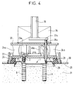
La figure 5 représente l'ensemble de cet exemple de réalisation, en représentant en outre des moyens permettant de déplacer verticalement la plaque support 22, et de déplacer verticalement l'étrier 39. Ces moyens comportent :
- une poutre horizontale 45 et deux guides cylindriques verticaux 43a et 43b, constituant un portique ;
- une pièce coulissante 42 coulissant verticalement en étant guidée par les deux guides 43a et 43b ;
- un premier vérin hydraulique 44 ayant une extrémité fixée à la poutre 45 et l'autre extrémité fixée à la pièce coulissante 42 ;
- les deux bras verticaux
40a et 40b reliant la pièce coulissante 42 à laplaque support 22 ; - un second vérin hydraulique 41 ayant une extrémité fixée à la pièce coulissante 42 et ayant son autre extrémité fixée à l'étrier 39 qui enjambe le dispositif de
vibration 35 ; - et une unité de commande UC reliée :
- -- à un capteur de
position 46 fixé d'une part à la poutre 45 et d'autre part à la pièce coulissante 42 pour déterminer l'altitude de la selle 1 par rapport à laplaque 30 qui repose sur lasurface 25 de la dalle de béton 31 ; - -- à un capteur de position CP solidaire de la poutre 45, pour déterminer l'altitude de la
plaque 30 par rapport à un plan de référence appelé plan laser parce qu'il est repéré par un faisceau laser tournant dans un plan donné ; - -- au vérin 44 par deux tuyaux pour l'actionner ;
- -- au vérin 41 par deux tuyaux pour l'actionner ;
- -- et au dispositif de
vibration 35 par deux tuyaux pour l'actionner.
- -- à un capteur de
- a
horizontal beam 45 and two verticalcylindrical guides 43a and 43b, constituting a gantry; - a sliding
part 42 sliding vertically while being guided by the twoguides 43a and 43b; - a first
hydraulic cylinder 44 having one end fixed to thebeam 45 and the other end fixed to the slidingpiece 42; - the two
vertical arms part 42 to thesupport plate 22; - a second
hydraulic cylinder 41 having one end fixed to the slidingpiece 42 and having its other end fixed to thestirrup 39 which spans thevibration device 35; - and a control unit UC connected:
- - a
position sensor 46 fixed on the one hand to thebeam 45 and on the other hand to the slidingpart 42 to determine the altitude of thesaddle 1 relative to theplate 30 which rests on thesurface 25 of theconcrete slab 31; - - A position sensor CP secured to the
beam 45, to determine the altitude of theplate 30 relative to a reference plane called the laser plane because it is identified by a laser beam rotating in a given plane; - - to the
jack 44 by two pipes to actuate it; - - to the
jack 41 by two pipes to actuate it; - - And to the
vibration device 35 by two pipes to activate it.
- - a
L'unité de commande UC commande plusieurs étapes successives. La figure 6 illustre une première étape au cours de laquelle la selle 1 est mise en place manuellement ou automatiquement, à l'intérieur du réceptacle 28, en insérant les tiges filetées des goujons dans les pinces hydrauliques 23a et 23b (Cette dernière n'est pas représentée). Les vérins 44 et 41 sont rétractés, ce qui laisse de l'espace entre le tube 21 et le réceptacle 28 pour accéder à l'intérieur de ce dernier.The control unit UC controls several successive stages. FIG. 6 illustrates a first step during which the
La figure 7 illustre une deuxième étape au cours de laquelle la selle 1 est enfoncée rapidement.Pendant toute cette étape, le dispositif de vibration 35 est activé avec une amplitude et une fréquence adaptées pour pour faciliter la pénétration de la selle 1 dans la dalle de béton 31, en rendant le béton plus fluide au voisinage des tiges d'ancrage. Les blocs de caoutchouc 24a, etc... permettent à la plaque 32 de se déplacer légèrement dans toutes les directions, par rapport à la plaque 22. Le vérin 44 est actionné pour enfoncer la selle 1 jusqu'à une position voisine de la position définitive prévue, à quelques millimètres près. Le vérin 44 déplace : la pièce coulissante 42, les bras 40a et 40b (non représentés), la plaque support 22, et le réceptacle 28 qui lui sont associés. La selle 1 est donc poussée dans le béton liquéfié par les vibrations. Le réceptacle 28 est abaissé jusqu'à être au voisinage de la surface 25 de la dalle de béton. Il est à remarquer que les doigts de guidage 26a, etc, sont encore en position relevée et ne sont pas au contact de la selle 1.FIG. 7 illustrates a second step during which the
La figure 8 illustre une troisiéme étape de l'insertion de la selle 1, consistant à achever l'enfoncement à une vitesse plus faible, adaptée à un positionnement précis, jusqu'à la profondeur définitive prévue pour la selle. Le vérin 44 est activé de nouveau, mais avec une vitesse plus faible. Le dispositif de vibration 35 est activé, mais l'amplitude et la fréquence des vibrations sont adaptées pour un positionnement précis de la selle 1. Le réceptacle 28 et la plaque 30, qui sont presque jointifs, confinent le béton et le forcent à remonter dans les bossages 5 et 10. Quand la selle 1 a atteint la position prévue, le dispositif de vibration 35 et le vérin 44 sont arrêtés.FIG. 8 illustrates a third step of inserting the
La figure 9 illustre une quatrième étape pendant laquelle le dispositif de vibration 35 est arrêté. Le vérin 41 est activé à son tour. ll abaisse l'étrier 39 qui est solidaire de la pièce 33a (partiellement représentée) et de la pièce 33b (non représentée), ces pièces 33a et 33b supportant les doigts 26a, etc... L'étrier 39 s'abaisse jusqu'à buter sur la plaque 32. Les extrémités des doigts 26a, etc... arrivent alors en contact avec la partie plane de la selle 1. Si la selle 1 n'est pas parfaitement positionnée dans le plan horizontal, les doigts frottent sur les parois verticales des bossages 5 et 10 de la selle 1 et provoquent un léger déplacement de la selle 1, dans le plan horizontal, pour repositionner la selle 1 dans une position bien définie par les huit doigts. Les vibrations ayant cessé, le béton reprend progressivement sa consistance ferme. Les pinces 23a, etc...sont maintenues serrées, et les doigts 26a, etc... sont maintenus dans cette position jusqu'à ce que l'augmentation de la viscosité du béton soit suffisante pour empêcher tout déplacement de la selle lors de la remontée des doigts.FIG. 9 illustrates a fourth step during which the
Les pinces hydrauliques 23a et 23b sont ensuite commandées pour relâcher les goujons de la selle 1.Puis le vérin 41 est activé en sens inverse pour remonter les doigts 26a, etc... Puis le vérin 44 est activé en sens inverse pour remonter toute la partie mobile du dispositif d'insertion.The
Les figures 10 et 11 représentent respectivement deux vues de face d'une machine mobile permettant l'insertion de deux selles simultanément. Sur la figure 10, la machine est dans un état permettant de la déplacer et de préparer l'insertion d'une selle. Sur la figure 11, la machine est en train d'insérer une selle dans une dalle de béton frais 62. La figure 12 représente une vue de dessus. Sur ces figures, la machine a déjà inséré des selles 70 à 76 dans une dalle de béton 62.Figures 10 and 11 respectively represent two front views of a mobile machine allowing the insertion of two saddles simultaneously. In Figure 10, the machine is in a state to move it and prepare the insertion of a saddle. In Figure 11, the machine is inserting a saddle into a fresh
Cet exemple de réalisation comporte une plate-forme mobile 52 supportant deux dispositifs d'insertion 51a et 51b, identiques entre eux et qui peuvent être analogues au dispositif d'insertion représenté sur les figures 3 à 5, et qui a été décrit précédemment. Ils comportent notamment des capteurs de position 64a, respectivement 64b, analogues au capteur CP ; et des unités de commande UC1, respectivement UC2, analogue à l'unité de commande UC. Les dispositifs 51a et 51b sont montés sur un chariot 63 qui est solidaire de la plate-forme 52 et mobile par rapport à celle-ci selon deux axes horizontaux, orthogonaux entre eux. D'autre part, un ensemble de vérins, non représentés, permet d'abaisser les dispositifs 51a et 51b jusqu'à ce que leurs bases (tôle 30) reposent sur la surface de la dalle de béton 62. Les dispositifs 51a et 51b traversent le chariot 63 par des ouvertures 61a et 61b respectivement, et en traversent la plateforme 52 par une ouverture 62.This exemplary embodiment comprises a
La plate-forme 52 est montée sur quatre chenilles 53a, 53b, 53c, 53d, par l'intermédiaire de quatre bras horizontaux articulés 55a, 55b, 55c, 55d, permettant de régler l'écartement entre les chenilles, et par l'intermédiaire de quatre jambes verticales 57a, 57b, 57c, 57d, permettant de régler indépendamment la hauteur de chaque bras 55a, 55b, 55c, 55d, respectivement par rapport aux chenilles 53a, 53b, 53c, 53d, reposant sur le sol.The
La position de la plate-forme 52 est asservie selon trois axes orthogonaux, au moyens d'une unité de commande UC3, de telle sorte qu'elle suit le profil prévu pour le chemin de roulement, par conséquent elle suit la surface de la dalle 62. Les jambes 54a et 54b supportent respectivement des capteurs 58a et 58b qui suivent un guide 57 parallèle au profil en long des rails à installer. Ce guide 57 porte des repères, afin d'asservir la position de la plate-forme 52 selon deux axes horizontaux en se référant à ce guide 57. La plate-forme 52 enjambe la dalle de béton 62 et se déplace le long de cette dalle 62 grâce à des moteurs actionnant les chenilles 53a, ..., 53d.The position of the
D'autre part, les jambes 54a et 54b portent respectivement des capteurs 60a et 60b permettant de déterminer les altitudes respectives des bras 55a et 55b par rapport à un plan laser, compte tenu du réglage de hauteur de ces bras par rapport aux jambes 54a et 54b. La connaissance de ces altitudes permet d'asservir ces altitudes à des valeurs de consigne prédéterminées pour que la plate-forme 52 suive le profil de la voie.On the other hand, the
Le béton utilisé a une consistance ferme. La dalle 62 a été fraîchementcoulée, vibrée en place, rectifiée, et lissée, par une machine classique à coffrages glissants, telles que celles utilisée pour faire des chaussées en béton, pour autoroute. Elle donne à la surface de la dalle une position déduite de la position prévue pour le plan de roulement de la voie, avec une précision de l'ordre de 2 millimètres, grâce à des asservissements de position classiques.The concrete used has a firm consistency. The
Les dispositifs d'insertion de selles, 51a et 51b, sont écartés d'un intervalle correspondant à l'intervalle prévu pour les rails. Le chariot mobile 63 les déplace ensemble et permet d'affiner la position d'insertion, avec une précision de l'ordre d'un millimètre selon deux axes horizontaux, encore meilleure que celle procurée par la plate-forme 52.The saddle inserts, 51a and 51b, are spaced apart by an interval corresponding to the interval provided for the rails. The
Le chariot mobile 63 porte un capteur de position 59 qui permet d'asservir la position du chariot 63 selon deux axes horizontaux, en se référant à la position du même guide 57, mais avec une tolérance plus fine que la tolérance sur la position de la plate-forme 52. Le chariot est déplacé par deux moteurs, non représentés , commandés par une unité de commande UC4, en fonction des mesures faites par le capteur 59 et en fonction de la position prévue pour les deux selles à insérer.The
L'asservissement des dispositifs d'insertion 51a et 51b selon un axe vertical, par les unités de commande UC1 et UC2, permet d'insérer chaque selle avec une précision d'altitude de l'ordre d'un millimètre, encore meilleure que la précision obtenue sur l'altitude de la surface de la couche de béton 62.The slaving of the
Les dispositifs d'asservissement de position, se référant à la position d'un guide et à la position d'un plan laser, sont des dispositifs classiques. Mais d'autres types connus de dispositif d'asservissement de position pourraient aussi être utilisés pour obtenir une position précise de chaque selle.Position control devices, referring to the position of a guide and the position of a laser plane, are conventional devices. However, other known types of position control device could also be used to obtain a precise position of each saddle.
Selon une variante de réalisation, les dispositifs d'insertion 51a et 51b pourraient être montés directement sur la machine utilisée pour couler en place la dalle de béton 62, au lieu de la plate-forme 52. La réalisation de cette machine ne sera pas décrite car elle est analogue à la réalisation d'une machine utilisée classiquement pour faire des autoroutes en béton.According to an alternative embodiment, the
Claims (9)
caractérisé en ce que les moyens (58a, 58b, 59, 60a, 60b, UC1, UC2, UC3, UC4) pour déterminer la position et pour commander les moyens pour enfoncer déterminent la position de chaque selle selon trois axes, ou un autre repère équivalent, par rapport à la position prévue pour cette selle.Device according to claim 5, for placing, with precision, in a concrete slab (62), at least one saddle (70 to 76) intended to support a rail;
characterized in that the means (58a, 58b, 59, 60a, 60b, UC1, UC2, UC3, UC4) for determining the position and for controlling the means for depressing determine the position of each saddle along three axes, or another reference equivalent, compared to the position provided for this saddle.
Applications Claiming Priority (2)
| Application Number | Priority Date | Filing Date | Title |
|---|---|---|---|
| FR9605099 | 1996-04-23 | ||
| FR9605099A FR2747698B1 (en) | 1996-04-23 | 1996-04-23 | PROCESS FOR PRECISION PLACING AN INSERT INTO CONCRETE, DEVICE FOR IMPLEMENTING THIS PROCESS, AND RAIL TRACK OBTAINED BY THIS PROCESS |
Publications (3)
| Publication Number | Publication Date |
|---|---|
| EP0803609A2 true EP0803609A2 (en) | 1997-10-29 |
| EP0803609A3 EP0803609A3 (en) | 1998-08-05 |
| EP0803609B1 EP0803609B1 (en) | 2003-01-15 |
Family
ID=9491496
Family Applications (1)
| Application Number | Title | Priority Date | Filing Date |
|---|---|---|---|
| EP97400910A Expired - Lifetime EP0803609B1 (en) | 1996-04-23 | 1997-04-22 | Method for accurately placing an insert in concrete, apparatus for performing said method , and railway track obtained through the method |
Country Status (4)
| Country | Link |
|---|---|
| EP (1) | EP0803609B1 (en) |
| AT (1) | ATE231203T1 (en) |
| DE (1) | DE69718371T2 (en) |
| FR (1) | FR2747698B1 (en) |
Cited By (10)
| Publication number | Priority date | Publication date | Assignee | Title |
|---|---|---|---|---|
| FR2812671A1 (en) | 2000-08-01 | 2002-02-08 | Alstom | GUIDING METHOD OF A DEVICE FOR INSERTING ELEMENTS INTO THE GROUND FOR THE PRODUCTION OF A STRUCTURE AND DEVICE FOR INSERTING AT LEAST ONE ELEMENT IN THE GROUND USING SUCH A GUIDING METHOD |
| FR2833023A1 (en) | 2001-12-05 | 2003-06-06 | Alstom | METHOD OF CONSTRUCTING A RAIL TRACK IN WHICH A CONCRETE TRACK SLAB IS MADE AND INSERTED IN THE TRACK SLOT ANCHORING ELEMENTS OF THE RAIL TRACK |
| US7325316B2 (en) | 2006-02-09 | 2008-02-05 | Alstom Transport Sa | Device and method for inserting elements into the ground, mechanism for this device and system using this device |
| US7428778B2 (en) | 2006-02-23 | 2008-09-30 | Alstom Transport Sa | Method and a system for inserting elements in the ground, a data recording medium for the method |
| FR2941973A1 (en) * | 2009-02-12 | 2010-08-13 | Alstom Transport Sa | Method for laser guiding of rail bearing plate insertion device for forming railway track, involves calculating position of arm from known position of arm relative to portion and position of portion relative to measurement station |
| FR3003276A1 (en) * | 2013-03-12 | 2014-09-19 | Alstom Transport Sa | METHOD FOR CONSTRUCTING A RAILWAY COMPRISING AN ANTI-VIBRATILE BED |
| EP3031983A1 (en) | 2014-11-10 | 2016-06-15 | ALSTOM Transport Technologies | An improved method for guiding a device for inserting elements into the ground for the building of a structure; insertion device and associated vehicle |
| EP3409836A1 (en) * | 2017-06-01 | 2018-12-05 | ALSTOM Transport Technologies | Method of manufacturing a railroad support, associated railroad support and railway installation |
| CN110952391A (en) * | 2019-12-17 | 2020-04-03 | 广东石油化工学院 | Pouring and screw inserting integrated machine for screws for train track sleepers |
| CN116065427A (en) * | 2023-01-05 | 2023-05-05 | 中建八局第一建设有限公司 | A prefabricated CRTSⅢ slab ballastless track structure and construction method |
Families Citing this family (1)
| Publication number | Priority date | Publication date | Assignee | Title |
|---|---|---|---|---|
| CN114622449B (en) * | 2022-03-10 | 2023-07-07 | 中国空气动力研究与发展中心高速空气动力研究所 | High-precision positioning method for reserved hole of track beam |
Family Cites Families (3)
| Publication number | Priority date | Publication date | Assignee | Title |
|---|---|---|---|---|
| SE415868B (en) * | 1978-12-05 | 1980-11-10 | A Betong Ab | SET TO MANUFACTURE CONCRETE SLIPPING BULK AND MATERIAL SETUP FOR EXECUTION OF THE SET |
| EP0117323B1 (en) * | 1983-02-10 | 1987-08-26 | Guntert And Zimmermann Const. Div. Inc. | Apparatus and process for dowel insertion to concrete panel joints |
| DE3714581C2 (en) * | 1987-04-30 | 1995-04-27 | Hugo Bittlmayer | Device for the correct arrangement of prefabricated reinforcements in reinforced concrete element slabs |
-
1996
- 1996-04-23 FR FR9605099A patent/FR2747698B1/en not_active Expired - Fee Related
-
1997
- 1997-04-22 EP EP97400910A patent/EP0803609B1/en not_active Expired - Lifetime
- 1997-04-22 DE DE69718371T patent/DE69718371T2/en not_active Expired - Lifetime
- 1997-04-22 AT AT97400910T patent/ATE231203T1/en not_active IP Right Cessation
Cited By (17)
| Publication number | Priority date | Publication date | Assignee | Title |
|---|---|---|---|---|
| FR2812671A1 (en) | 2000-08-01 | 2002-02-08 | Alstom | GUIDING METHOD OF A DEVICE FOR INSERTING ELEMENTS INTO THE GROUND FOR THE PRODUCTION OF A STRUCTURE AND DEVICE FOR INSERTING AT LEAST ONE ELEMENT IN THE GROUND USING SUCH A GUIDING METHOD |
| KR100918504B1 (en) * | 2001-12-05 | 2009-09-24 | 알스톰 | A method of construction a rail track in which a concrete track slab is produced and rail track anchor members are inserted into the track slab |
| FR2833023A1 (en) | 2001-12-05 | 2003-06-06 | Alstom | METHOD OF CONSTRUCTING A RAIL TRACK IN WHICH A CONCRETE TRACK SLAB IS MADE AND INSERTED IN THE TRACK SLOT ANCHORING ELEMENTS OF THE RAIL TRACK |
| US6913717B2 (en) * | 2001-12-05 | 2005-07-05 | Alstom | Method of constructing a rail track in which a concrete track slab is produced and rail track anchor members are inserted into the track slab |
| US7325316B2 (en) | 2006-02-09 | 2008-02-05 | Alstom Transport Sa | Device and method for inserting elements into the ground, mechanism for this device and system using this device |
| CN101024931B (en) * | 2006-02-23 | 2012-02-15 | 阿尔斯通运输公司 | Process and system for inserting elements into the ground, medium for storing data for this process |
| RU2430209C2 (en) * | 2006-02-23 | 2011-09-27 | Альстом Транспорт Са | Method and system of elements installation into base |
| US7428778B2 (en) | 2006-02-23 | 2008-09-30 | Alstom Transport Sa | Method and a system for inserting elements in the ground, a data recording medium for the method |
| FR2941973A1 (en) * | 2009-02-12 | 2010-08-13 | Alstom Transport Sa | Method for laser guiding of rail bearing plate insertion device for forming railway track, involves calculating position of arm from known position of arm relative to portion and position of portion relative to measurement station |
| FR3003276A1 (en) * | 2013-03-12 | 2014-09-19 | Alstom Transport Sa | METHOD FOR CONSTRUCTING A RAILWAY COMPRISING AN ANTI-VIBRATILE BED |
| EP3031983A1 (en) | 2014-11-10 | 2016-06-15 | ALSTOM Transport Technologies | An improved method for guiding a device for inserting elements into the ground for the building of a structure; insertion device and associated vehicle |
| EP3409836A1 (en) * | 2017-06-01 | 2018-12-05 | ALSTOM Transport Technologies | Method of manufacturing a railroad support, associated railroad support and railway installation |
| FR3067045A1 (en) * | 2017-06-01 | 2018-12-07 | Alstom Transport Technologies | PROCESS FOR MANUFACTURING RAILWAY SUPPORT, RAILWAY SUPPORT AND RAILWAY INSTALLATION THEREFOR |
| US11085153B2 (en) | 2017-06-01 | 2021-08-10 | Alstom Transport Technologies | Method for manufacturing a railway track support, associated railway track support and railway installation |
| CN110952391A (en) * | 2019-12-17 | 2020-04-03 | 广东石油化工学院 | Pouring and screw inserting integrated machine for screws for train track sleepers |
| CN110952391B (en) * | 2019-12-17 | 2021-06-25 | 广东石油化工学院 | An integrated machine for pouring and inserting screws for railway sleepers |
| CN116065427A (en) * | 2023-01-05 | 2023-05-05 | 中建八局第一建设有限公司 | A prefabricated CRTSⅢ slab ballastless track structure and construction method |
Also Published As
| Publication number | Publication date |
|---|---|
| DE69718371D1 (en) | 2003-02-20 |
| EP0803609B1 (en) | 2003-01-15 |
| FR2747698B1 (en) | 2003-11-14 |
| ATE231203T1 (en) | 2003-02-15 |
| DE69718371T2 (en) | 2003-11-20 |
| FR2747698A1 (en) | 1997-10-24 |
| EP0803609A3 (en) | 1998-08-05 |
Similar Documents
| Publication | Publication Date | Title |
|---|---|---|
| EP0803609B1 (en) | Method for accurately placing an insert in concrete, apparatus for performing said method , and railway track obtained through the method | |
| EP1318239B1 (en) | Method for building a ballastless track | |
| EP0102340B1 (en) | Method of making reinforced concrete constructions such as subways, road tunnels and the like; prefabricated concrete elements for making such constructions | |
| EP0939164A1 (en) | Construction method for a railway track | |
| FR3036711A1 (en) | TRANSPORT TRACK SECTION GUIDE FOR BALLAST-FREE TRACK AND BALLAST-FREE TRACK OF A PLURALITY OF SUCH SECTIONS | |
| FR2523627A1 (en) | METHOD FOR CONFORTING ARCHES OR SIMILAR CONSTRUCTIONS | |
| EP0197844A1 (en) | Installation and process for manufacturing reinforced-concrete elements, in particular prestressed concrete sections | |
| FR2671119A1 (en) | CONCRETE CONSTRUCTION ELEMENTS, PRE-STRESSED, OF THE PRELABS TYPE, INSTALLATION AND PROCESS FOR THEIR MANUFACTURE. | |
| FR2669259A1 (en) | Process for the manufacture of prefabricated arch units | |
| EP2666907B1 (en) | Railway track with sleepers on continuous concrete slab and manufacturing method | |
| EP2369058B1 (en) | Method of compacting soils, application of this method, and device for carrying out the method | |
| EP3617409B1 (en) | Device and method for mechanical backfilling of trenches | |
| EP3486369B1 (en) | Assembly comprising prefabricated slab for railway and a sleeper, installation method | |
| EP2351884A1 (en) | Supporting module for a prefabricated railway track, railway track, section and method for mounting railway tracks | |
| EP3409836B1 (en) | Method of manufacturing a railroad support | |
| FR2683838A1 (en) | Method and device for constructing a reinforced concrete slab having a predefined thickness | |
| EP1457599B1 (en) | Method for constructing a railroad level-crossing | |
| FR2698114A1 (en) | Railway track foundation method using bored piles for slabs - comprises drilling high pressure air and water spoil removal and grouting pile cap construction track lifting and supporting slab construction | |
| EP1460175A1 (en) | Method for laying a traffic or railway platform and thus obtained platform | |
| FR2909400A1 (en) | Fresh concrete surface leveling and polishing device for tennis court, has beam with aluminum section that is provided with guiding groove, motor trains co-operated with formwork scale, and polishing head with chassis suspended on beam | |
| FR2731238A1 (en) | Installation procedure for railway tracks on solid foundations in tunnels or viaduct | |
| FR2839990A1 (en) | Prefabricated Civil engineering structure for installing passage under rail track comprises portico with upper crosspiece connecting two vertical abutments extended by additional spans supported by cover plate on talus ridge | |
| EP3336249B1 (en) | Method for manufacturing a track support element, track support element obtained through said method and railway track comprising said element | |
| EP0952307A1 (en) | Method for the construction of a structure under an embankment supporting a railway track or a roadway | |
| FR2791712A1 (en) | Process for laying rail track section on rigid support with height adjustment uses swingle bar for implementing process |
Legal Events
| Date | Code | Title | Description |
|---|---|---|---|
| PUAI | Public reference made under article 153(3) epc to a published international application that has entered the european phase |
Free format text: ORIGINAL CODE: 0009012 |
|
| AK | Designated contracting states |
Kind code of ref document: A2 Designated state(s): AT BE CH DE GB LI NL |
|
| PUAL | Search report despatched |
Free format text: ORIGINAL CODE: 0009013 |
|
| AK | Designated contracting states |
Kind code of ref document: A3 Designated state(s): AT BE CH DE GB LI NL |
|
| 17P | Request for examination filed |
Effective date: 19990205 |
|
| 17Q | First examination report despatched |
Effective date: 20011105 |
|
| GRAG | Despatch of communication of intention to grant |
Free format text: ORIGINAL CODE: EPIDOS AGRA |
|
| GRAG | Despatch of communication of intention to grant |
Free format text: ORIGINAL CODE: EPIDOS AGRA |
|
| GRAH | Despatch of communication of intention to grant a patent |
Free format text: ORIGINAL CODE: EPIDOS IGRA |
|
| GRAH | Despatch of communication of intention to grant a patent |
Free format text: ORIGINAL CODE: EPIDOS IGRA |
|
| GRAA | (expected) grant |
Free format text: ORIGINAL CODE: 0009210 |
|
| AK | Designated contracting states |
Kind code of ref document: B1 Designated state(s): AT BE CH DE GB LI NL |
|
| REG | Reference to a national code |
Ref country code: GB Ref legal event code: FG4D Free format text: NOT ENGLISH Ref country code: CH Ref legal event code: EP |
|
| REF | Corresponds to: |
Ref document number: 69718371 Country of ref document: DE Date of ref document: 20030220 Kind code of ref document: P |
|
| REG | Reference to a national code |
Ref country code: CH Ref legal event code: NV Representative=s name: CABINET ROLAND NITHARDT CONSEILS EN PROPRIETE INDU |
|
| GBT | Gb: translation of ep patent filed (gb section 77(6)(a)/1977) |
Effective date: 20030408 |
|
| PLBE | No opposition filed within time limit |
Free format text: ORIGINAL CODE: 0009261 |
|
| STAA | Information on the status of an ep patent application or granted ep patent |
Free format text: STATUS: NO OPPOSITION FILED WITHIN TIME LIMIT |
|
| 26N | No opposition filed |
Effective date: 20031016 |
|
| BECA | Be: change of holder's address |
Owner name: Z.I. DE LA SAULE, F-71230 SAINT-VALLIER (FR) Effective date: 20050928 Owner name: *METALLIANCEIMMEUBLE "LE SEXTANT" 2 QUAI MICHELET Effective date: 20050928 Owner name: *CEGELEC Effective date: 20050928 |
|
| BECH | Be: change of holder |
Owner name: Z.I. DE LA SAULE, F-71230 SAINT-VALLIER (FR) Effective date: 20050928 Owner name: *METALLIANCEIMMEUBLE "LE SEXTANT" 2 QUAI MICHELET Effective date: 20050928 Owner name: *CEGELEC Effective date: 20050928 |
|
| BECN | Be: change of holder's name |
Owner name: *METALLIANCE Effective date: 20050928 Owner name: *CEGELEC Effective date: 20050928 |
|
| REG | Reference to a national code |
Ref country code: CH Ref legal event code: PUE Owner name: CEGELEC Free format text: CEGELEC#IMMEUBLE "LE SEXTANT", 2 QUAI MICHELET#92300 LEVALLOIS PERRET (FR) $ SOCIETE NOUVELLE FRANEX#42, RUE NATIONALE#F-71420 GENELARD (FR) -TRANSFER TO- CEGELEC#IMMEUBLE "LE SEXTANT", 2 QUAI MICHELET#92300 LEVALLOIS PERRET (FR) $ SOCIETE ADVENS#ZI SAINTE ELISABETH#71300 MONTCEAU-LES-MINES (FR) Ref country code: CH Ref legal event code: PUE Owner name: CEGELEC Free format text: CEGELEC#IMMEUBLE "LE SEXTANT", 2 QUAI MICHELET#92300 LEVALLOIS PERRET (FR) $ SOCIETE ADVENS#ZI SAINTE ELISABETH#71300 MONTCEAU-LES-MINES (FR) -TRANSFER TO- CEGELEC#IMMEUBLE "LE SEXTANT", 2 QUAI MICHELET#92300 LEVALLOIS PERRET (FR) $ SOCIETE METALLIANCE#ZI DE LA SAULE#71230 SAINT-VALLIER (FR) |
|
| NLS | Nl: assignments of ep-patents |
Owner name: METALLIANCE Effective date: 20050927 Owner name: CEGELEC Effective date: 20050927 Owner name: AILLOT-MPI Effective date: 20050927 |
|
| NLT1 | Nl: modifications of names registered in virtue of documents presented to the patent office pursuant to art. 16 a, paragraph 1 |
Owner name: CEGELEC Owner name: ADVENS |
|
| REG | Reference to a national code |
Ref country code: GB Ref legal event code: 732E |
|
| REG | Reference to a national code |
Ref country code: GB Ref legal event code: 732E |
|
| BECA | Be: change of holder's address |
Owner name: Z.I. DE LA SAULE, F-71230 SAINT-VALLIER (FR) Effective date: 20050928 Owner name: *METALLIANCEIMMEUBLE "LE SEXTANT" 2 QUAI MICHELET Effective date: 20050928 Owner name: *CEGELEC Effective date: 20050928 |
|
| BECH | Be: change of holder |
Owner name: Z.I. DE LA SAULE, F-71230 SAINT-VALLIER (FR) Effective date: 20050928 Owner name: *METALLIANCEIMMEUBLE "LE SEXTANT" 2 QUAI MICHELET Effective date: 20050928 Owner name: *CEGELEC Effective date: 20050928 |
|
| BECN | Be: change of holder's name |
Owner name: *METALLIANCE Effective date: 20050928 Owner name: *CEGELEC Effective date: 20050928 |
|
| PGFP | Annual fee paid to national office [announced via postgrant information from national office to epo] |
Ref country code: NL Payment date: 20100413 Year of fee payment: 14 Ref country code: DE Payment date: 20100423 Year of fee payment: 14 Ref country code: AT Payment date: 20100415 Year of fee payment: 14 |
|
| PGFP | Annual fee paid to national office [announced via postgrant information from national office to epo] |
Ref country code: BE Payment date: 20100419 Year of fee payment: 14 |
|
| PGFP | Annual fee paid to national office [announced via postgrant information from national office to epo] |
Ref country code: GB Payment date: 20100420 Year of fee payment: 14 |
|
| BERE | Be: lapsed |
Owner name: *METALLIANCE Effective date: 20110430 Owner name: *CEGELEC Effective date: 20110430 |
|
| REG | Reference to a national code |
Ref country code: DE Ref legal event code: R119 Ref document number: 69718371 Country of ref document: DE |
|
| REG | Reference to a national code |
Ref country code: DE Ref legal event code: R119 Ref document number: 69718371 Country of ref document: DE |
|
| REG | Reference to a national code |
Ref country code: NL Ref legal event code: V1 Effective date: 20111101 |
|
| GBPC | Gb: european patent ceased through non-payment of renewal fee |
Effective date: 20110422 |
|
| REG | Reference to a national code |
Ref country code: AT Ref legal event code: MM01 Ref document number: 231203 Country of ref document: AT Kind code of ref document: T Effective date: 20110422 |
|
| PG25 | Lapsed in a contracting state [announced via postgrant information from national office to epo] |
Ref country code: BE Free format text: LAPSE BECAUSE OF NON-PAYMENT OF DUE FEES Effective date: 20110430 Ref country code: NL Free format text: LAPSE BECAUSE OF NON-PAYMENT OF DUE FEES Effective date: 20111101 |
|
| PGFP | Annual fee paid to national office [announced via postgrant information from national office to epo] |
Ref country code: CH Payment date: 20111026 Year of fee payment: 15 |
|
| PG25 | Lapsed in a contracting state [announced via postgrant information from national office to epo] |
Ref country code: GB Free format text: LAPSE BECAUSE OF NON-PAYMENT OF DUE FEES Effective date: 20110422 Ref country code: AT Free format text: LAPSE BECAUSE OF NON-PAYMENT OF DUE FEES Effective date: 20110422 |
|
| REG | Reference to a national code |
Ref country code: CH Ref legal event code: PL |
|
| PG25 | Lapsed in a contracting state [announced via postgrant information from national office to epo] |
Ref country code: CH Free format text: LAPSE BECAUSE OF NON-PAYMENT OF DUE FEES Effective date: 20120430 Ref country code: LI Free format text: LAPSE BECAUSE OF NON-PAYMENT OF DUE FEES Effective date: 20120430 |
|
| PG25 | Lapsed in a contracting state [announced via postgrant information from national office to epo] |
Ref country code: DE Free format text: LAPSE BECAUSE OF NON-PAYMENT OF DUE FEES Effective date: 20111031 |