EP0803607A2 - Rouleau à réglage de la flexion - Google Patents
Rouleau à réglage de la flexion Download PDFInfo
- Publication number
- EP0803607A2 EP0803607A2 EP97105205A EP97105205A EP0803607A2 EP 0803607 A2 EP0803607 A2 EP 0803607A2 EP 97105205 A EP97105205 A EP 97105205A EP 97105205 A EP97105205 A EP 97105205A EP 0803607 A2 EP0803607 A2 EP 0803607A2
- Authority
- EP
- European Patent Office
- Prior art keywords
- adjustment roller
- bending adjustment
- roller according
- slide
- valves
- Prior art date
- Legal status (The legal status is an assumption and is not a legal conclusion. Google has not performed a legal analysis and makes no representation as to the accuracy of the status listed.)
- Granted
Links
Images

Classifications
-
- F—MECHANICAL ENGINEERING; LIGHTING; HEATING; WEAPONS; BLASTING
- F16—ENGINEERING ELEMENTS AND UNITS; GENERAL MEASURES FOR PRODUCING AND MAINTAINING EFFECTIVE FUNCTIONING OF MACHINES OR INSTALLATIONS; THERMAL INSULATION IN GENERAL
- F16C—SHAFTS; FLEXIBLE SHAFTS; ELEMENTS OR CRANKSHAFT MECHANISMS; ROTARY BODIES OTHER THAN GEARING ELEMENTS; BEARINGS
- F16C13/00—Rolls, drums, discs, or the like; Bearings or mountings therefor
- F16C13/02—Bearings
- F16C13/022—Bearings supporting a hollow roll mantle rotating with respect to a yoke or axle
- F16C13/024—Bearings supporting a hollow roll mantle rotating with respect to a yoke or axle adjustable for positioning, e.g. radial movable bearings for controlling the deflection along the length of the roll mantle
- F16C13/026—Bearings supporting a hollow roll mantle rotating with respect to a yoke or axle adjustable for positioning, e.g. radial movable bearings for controlling the deflection along the length of the roll mantle by fluid pressure
- F16C13/028—Bearings supporting a hollow roll mantle rotating with respect to a yoke or axle adjustable for positioning, e.g. radial movable bearings for controlling the deflection along the length of the roll mantle by fluid pressure with a plurality of supports along the length of the roll mantle, e.g. hydraulic jacks
-
- D—TEXTILES; PAPER
- D21—PAPER-MAKING; PRODUCTION OF CELLULOSE
- D21G—CALENDERS; ACCESSORIES FOR PAPER-MAKING MACHINES
- D21G1/00—Calenders; Smoothing apparatus
- D21G1/02—Rolls; Their bearings
- D21G1/0206—Controlled deflection rolls
- D21G1/0213—Controlled deflection rolls with deflection compensation means acting between the roller shell and its supporting member
- D21G1/022—Controlled deflection rolls with deflection compensation means acting between the roller shell and its supporting member the means using fluid pressure
Definitions
- the invention relates to a bending adjustment roller with a roller shell which is supported on a carrier via support elements, pressure chambers being provided between the support elements and the carrier and each pressure chamber being connected to a supply line.
- Bending adjustment rollers of this type which are also referred to as deflection adjustment rollers, are used in roller machines, such as calenders or smoothing units, in order to apply pressure to continuous material webs, in particular paper webs.
- a bending adjustment roller with a counter roller forms a nip through which the material web is guided.
- the support elements are provided with which the pressure conditions in the roll gap can be adjusted. The support elements are acted upon by a pressure fluid, for example a hydraulic oil. Your training is known per se.
- the invention has for its object to be able to bring about a rapid relief of the pressure chambers even with a fine resolution of the pressure distribution.
- each pressure chamber is connected directly to an outlet channel provided in addition to the supply line and which can be closed by means of a drain valve.
- the hydraulic fluid can rather be discharged from the pressure chamber via the outlet channel. So that this takes place only when this is desired, that is, not during normal roller operation, the drain valve is provided, with which the relief of the pressure chambers can be controlled in a targeted manner.
- the outlet channel preferably opens into a space between the roll shell and the carrier. Oil, which always gets there, for example, when using hydrostatic support elements, is continuously drained from this space, so that the annular space between the roller shell and the carrier is not filled with oil and is largely depressurized. Therefore, if you open the drain valve, the oil from the pressure chamber with the pressure there is pressed out into the space between the roll shell and the carrier. No pressure reduction is necessary beforehand, as would be the case, for example, in the supply lines.
- the outlet channel has a lower flow resistance than the supply line. This can generally be achieved in that the outlet channel has a shorter length than the supply line.
- the outlet channel can also be provided with a larger flow cross section.
- Each pressure chamber preferably has its own supply line and its own outlet channel. In many cases, it is sufficient to combine the individual support elements and thus the individual pressure chambers in groups and to control them in groups. If you provide each support element with its own supply line, the control of the pressure distribution is correspondingly easier. The unloading can then also take place at a higher speed because the hydraulic fluid can flow out of each pressure chamber immediately.
- the outlet duct preferably branches off from an intermediate duct between the pressure chamber and the supply line. Design changes in the area of the pressure chamber are therefore not necessary. In particular, flow conditions that have proven themselves can be maintained. It is only necessary to insert an additional channel in the carrier.
- the drain valves are advantageously placed on the outside of the carrier with at least part of their body. This simplifies production.
- the moving parts can then be accommodated in a housing which is attached to the outside of the carrier. Larger machining of the carrier can then be avoided.
- drain valves are arranged offset by approximately 90 ° to the position of the support elements. In this position, they least disturb the lifting movement of the roller shell. There is practically no restriction of the movement of the roller shell.
- all drain valves can be operated simultaneously. If a quick disconnection process is necessary, a single command is then sufficient to relieve all pressure chambers.
- the actuating device is preferably designed as a slide. Such a slide can be accommodated well on the carrier and operated from one end.
- the slide advantageously has a piston-cylinder device as the drive.
- a piston-cylinder device can then also be operated with hydraulic fluid, which is available in any case with the bending adjustment roller. No other pressure generation mechanisms are therefore necessary.
- the slide is designed at least at one end as a piston which is displaceably arranged in a cylinder. This facilitates manufacturing. A connection between the slide and the piston of the piston-cylinder device is not necessary. Rather, this is already given by the slide itself.
- the piston can also be designed as a plunger.
- the drain valves are preferably designed as slide valves with valve slides.
- the flow path is opened by pushing a through bore of the valve spool over a corresponding mouth of the outlet channel. If this overlap is not established, the drain valve is closed.
- Such a valve structure is easy to implement. Such a valve is relatively easy to operate.
- valve slides of the drain valves are preferably fastened to one another in the axial direction. A separate one Slider is then no longer necessary. The valve spools then themselves form the actuating device.
- each drain valve has a closure piece which can be moved into the mouth of the outlet channel. There it can either come into contact with an end face to bring about sealing, or it can be inserted into the mouth in the manner of a stopper, which likewise achieves sufficient tightness. In most cases, absolute tightness is not necessary because the support elements always have a certain leakage anyway.
- the slide acts on the closure pieces via an inclined surface.
- the axial movement can then be converted relatively easily into a radial movement of the closure pieces.
- the drain valves are preferably designed as self-opening valves. This is an additional security aspect. If, for example, a failure of the supply device occurs and no more pressure is available in the piston-cylinder device, the valves open, which causes the calender rolls to be separated quickly. If the valves were actuated the other way round, such a quick disconnection would no longer be guaranteed after the supply failure.
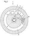
- a bending adjustment roller 1 has a roller shell 2 which is supported on a carrier 4 by means of support elements 3.
- the carrier 4 can also be referred to as the axis of the roller.
- the bending adjustment roller 1 is a jacketed roller, i.e. as a roller with a jacket stroke.
- Each support element has a pressure chamber 5, which in the present case can be acted upon individually with pressure fluid, for example hydraulic oil.
- pressure fluid for example hydraulic oil.
- the pressure chamber 5 is arranged between the support element 3 and the carrier 4.
- a supply line 6 is provided for each pressure chamber 5.
- the pressure in the pressure chamber can be controlled by the supply line 6.
- the supply lines 6 form a tube bundle 7, which is arranged in a central bore 8 of the carrier 4.
- the central bore 8 is connected to the pressure chambers 5 via intermediate channels 9.
- dividing walls 10 with seals 11 are arranged in the central bore 8 between the mouths of the intermediate channels 9 into the central bore 8.
- a supply line 6 opens at each partition 10. This can be seen in FIG. 2 in that the corresponding supply line 6 is no longer shown in section.
- counter elements 12 are arranged, which can also be acted upon by hydraulic fluid, on the one hand to bring about a faster lowering of the roll shell 2 and on the other hand to relieve the pressure on the roll ends.
- Slidable sealing and bearing arrangements 13 are also provided at the roller ends, as are generally known from bending adjustment rollers with a jacket stroke.
- an outlet channel 14 branches off from the intermediate channel 9 and can be closed with the aid of a drain valve 15. 2, the drain valve 15 is shown in its open position.
- the drain valve has a valve housing 16 which is placed on the outside of the carrier 4.
- the drain valve 15 is arranged offset by approximately 90 ° to the support elements 3. If the roller shell 2 is lowered, the drain valve 15 does not interfere even if, as shown, it is attached to the outside of the carrier 4.
- the outlet channel 14 opens into an annular space 17 between the roll shell 2 and the carrier 4.
- oil or other hydraulic fluid permanently flows, which must then be removed from there. Since there is a permanent drain or even a permanent pumping of oil out of this annular space 17, there is practically tank pressure in the annular space 17. Hydraulic fluid which is displaced from the pressure chamber 5 through the outlet channel 14 can then flow into the annular space 17 practically without counterpressure.
- the outlet channel 14 is relatively short. It only has to go from the intermediate channel 9 to the annular space 17, i.e. lead to the peripheral wall of the carrier 4. Even if the cross-section is the same size as the cross-section of a supply line 6, the flow resistance is significantly lower due to the shorter length. As soon as the drain valve 15 is opened, the hydraulic fluid can escape from the pressure chambers 5 more or less suddenly.
- the support elements 3 per se are known. For reasons of clarity, neither lines nor chokes are therefore shown in these support elements 3.
- the present support element 3 can have an annular piston, for example, so that the pressure chamber 5 is designed in a ring-like manner. But it can also be a support element 3 with two pistons. Another possible embodiment is shown in FIG. 1. However, the detailed design of the individual support elements 3 is not important. It is only important that hydraulic fluid, which is used in and of itself for pressurizing the support elements 3 in normal operation, can escape very quickly when the rollers are quickly separated via the outlet channel 14 and the drain valve 15.
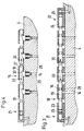
- FIG. 3 and 4 show examples of a design of the drain valve 15.
- the drain valve is designed as a slide valve 18. 3 shows the position in which the slide valve 18 is closed.
- All slide valves 18 have a common valve slide 19, which has a through hole 20 for each drain valve.
- This through hole 20 can be brought into overlap with the outlet channel 14 in a position of the valve slide 19.
- the hydraulic fluid can flow out of the pressure chamber 5.
- the through bore 20 is not in register with the outlet channel 14. The hydraulic fluid can then not flow through the valve spool 19 or past it.
- the valve housing 16 closes the mouth of the outlet channel 14 together with the valve slide 19.
- the valve spool 19 is driven by two piston-cylinder devices 21, 22 which are arranged at the two axial ends of the valve spool 19.
- the valve slide 19 is machined at both ends so that it itself acts as a piston 23, 24, which is inserted into a cylinder 25, 26, respectively.
- the valve spool 19 shifts to the right and closes the spool valves 18.
- the piston-cylinder device 22 is pressurized, the valve spool 19 shifts to the left and opens and the drain valves.
- the same hydraulic fluid that is also used to apply the pressure in the support elements can be used to actuate the piston-cylinder devices 21, 22.
- Fig. 4 shows another embodiment in which the drain valves 15 have a closure piece 27, which can be inserted in the manner of a plug into the mouth of the outlet channel 14. 4, the drain valves 15 are shown in their open state.
- the closure piece 27 is pressed into its open position by a compression spring 28. Hydraulic fluid can then flow out of the outlet channel 14 past the closure piece 27 into a space 29, from which it reaches the annular space 17 between the roll shell 2 and the carrier 4, not shown.
- the closure piece 27 is actuated via an inclined surface 30 by a slide 31 which can be displaced approximately in the axial direction parallel to the carrier 4, as shown by arrows 32, 33.
- a slide 31 which can be displaced approximately in the axial direction parallel to the carrier 4, as shown by arrows 32, 33.
- the valves 15 are closed.
- the valves 15 are opened. The same applies to the valves in FIG. 3.
- a piston-cylinder device 21 is also provided at the left end of the slide 31, which, like its corresponding counterpart in FIG. 3, can be acted upon by hydraulic fluid.
- the slider 31 When the slider 31 is then moved to the right, it acts on the inclined surface 30 of each closure piece 27 and moves it radially inward to close the mouth of the outlet channel 14.
- closure piece 27 can also act on an end face surrounding the mouth of the outlet channel 14. With the valve arrangement shown in Fig. 4, however, good tightness of the drain valve 15 is also guaranteed.
- Both the valve spool 19 in FIG. 3 and the spool 31 in FIG. 4 can be composed of several parts of the same design.
- the sections can be screwed together. If necessary, you can also use spacers between individual slide sections if this is necessary. With this configuration, it is ensured via the mechanical connection of the individual sections that all valves 15, 18 are opened or closed simultaneously.
Landscapes
- Physics & Mathematics (AREA)
- Fluid Mechanics (AREA)
- Engineering & Computer Science (AREA)
- General Engineering & Computer Science (AREA)
- Mechanical Engineering (AREA)
- Rolls And Other Rotary Bodies (AREA)
- Paper (AREA)
- Casting Or Compression Moulding Of Plastics Or The Like (AREA)
Applications Claiming Priority (2)
| Application Number | Priority Date | Filing Date | Title |
|---|---|---|---|
| DE19616275A DE19616275C2 (de) | 1996-04-24 | 1996-04-24 | Biegeeinstellwalze |
| DE19616275 | 1996-04-24 |
Publications (3)
| Publication Number | Publication Date |
|---|---|
| EP0803607A2 true EP0803607A2 (fr) | 1997-10-29 |
| EP0803607A3 EP0803607A3 (fr) | 1998-12-23 |
| EP0803607B1 EP0803607B1 (fr) | 2001-10-17 |
Family
ID=7792248
Family Applications (1)
| Application Number | Title | Priority Date | Filing Date |
|---|---|---|---|
| EP97105205A Expired - Lifetime EP0803607B1 (fr) | 1996-04-24 | 1997-03-27 | Rouleau à réglage de la flexion |
Country Status (3)
| Country | Link |
|---|---|
| US (1) | US5980438A (fr) |
| EP (1) | EP0803607B1 (fr) |
| DE (2) | DE19616275C2 (fr) |
Families Citing this family (5)
| Publication number | Priority date | Publication date | Assignee | Title |
|---|---|---|---|---|
| DE19632769C2 (de) * | 1996-08-14 | 2001-05-31 | Kuesters Eduard Maschf | Kalander mit einer Schnellöffnungseinrichtung |
| FI2920U1 (fi) * | 1997-02-28 | 1997-05-29 | Valmet Corp | Järjestely kuormituskengillä varustetussa taipumakompensoidussa telassa |
| FI120419B (fi) | 2006-11-24 | 2009-10-15 | Metso Paper Inc | Järjestely kenkätelan kuormituspaineen hallitsemiseksi |
| US20150150269A1 (en) * | 2012-08-01 | 2015-06-04 | Frito-Lay North America, Inc. | Continuous process and apparatus for making a pita chip |
| SG2013096128A (en) * | 2013-12-26 | 2015-07-30 | Zimplistic Pte Ltd | Sweeper mechanism for a food preparation appliance |
Family Cites Families (7)
| Publication number | Priority date | Publication date | Assignee | Title |
|---|---|---|---|---|
| DE3820974C3 (de) * | 1988-06-22 | 1996-03-21 | Kuesters Eduard Maschf | Dichtungsglied bzw. Walze |
| DE4011826C1 (fr) * | 1990-04-12 | 1991-08-01 | Eduard Kuesters Maschinenfabrik Gmbh & Co Kg, 4150 Krefeld, De | |
| DE4426512C2 (de) * | 1994-07-27 | 1997-07-17 | Voith Sulzer Papiermasch Gmbh | Durchbiegungseinstellwalze |
| DE4426513C2 (de) * | 1994-07-27 | 1997-07-17 | Voith Sulzer Papiermasch Gmbh | Durchbiegungseinstellwalze |
| DE4429499C1 (de) * | 1994-08-19 | 1995-11-16 | Kleinewefers Gmbh | Durchbiegungssteuerbare Walze für einen Kalander o. dgl. |
| DE4430268C1 (de) * | 1994-08-26 | 1995-11-02 | Kleinewefers Gmbh | Durchbiegungssteuerbare Walze für einen Kalander o. dgl. |
| DE4430667C1 (de) * | 1994-08-29 | 1996-02-08 | Voith Sulzer Papiermasch Gmbh | Durchbiegungsgesteuerte Walze |
-
1996
- 1996-04-24 DE DE19616275A patent/DE19616275C2/de not_active Expired - Fee Related
-
1997
- 1997-03-27 EP EP97105205A patent/EP0803607B1/fr not_active Expired - Lifetime
- 1997-03-27 DE DE59704920T patent/DE59704920D1/de not_active Expired - Lifetime
- 1997-04-21 US US08/844,681 patent/US5980438A/en not_active Expired - Fee Related
Also Published As
| Publication number | Publication date |
|---|---|
| DE19616275A1 (de) | 1997-11-06 |
| EP0803607A3 (fr) | 1998-12-23 |
| DE59704920D1 (de) | 2001-11-22 |
| DE19616275C2 (de) | 2002-09-12 |
| US5980438A (en) | 1999-11-09 |
| EP0803607B1 (fr) | 2001-10-17 |
Similar Documents
| Publication | Publication Date | Title |
|---|---|---|
| DE3003395C2 (de) | Verfahren zur Steuerung der Liniendruckverteilung einer Walze und entsprechende Walze | |
| DE2632452B1 (de) | Durchbiegungseinstellwalze | |
| DE19507086C2 (de) | Wasserhydraulik-Regelventil | |
| DE2736656C3 (de) | Durchbiegungseinstellwalze | |
| DE69921007T2 (de) | Kugel-Sitzventil mit pneumatischer Steuerung | |
| DE2550270B2 (de) | Durchbiegungsausgleichswalze | |
| EP0803607B1 (fr) | Rouleau à réglage de la flexion | |
| DE2850415C2 (de) | Durchbiegungseinstellwalze | |
| DE2056066B2 (de) | Abschalteinrichtung für die hydraulische Hilfskraft bei einer Hilfskraftlenkung für Fahrzeuge | |
| DE3889122T2 (de) | Selbst-belastende durchbiegungseinstellwalze. | |
| DE1293030B (de) | Druckmittelbetaetigter Linearsteller | |
| EP0697483B1 (fr) | Rouleau à réglage de la flexion pour une calandre ou similaire | |
| DE102009002627A1 (de) | Hydrostatisches Stützelement | |
| DE2248486C2 (de) | Hydraulischer Steuerschieber | |
| WO2012095327A1 (fr) | Dispositif de moulage par injection doté d'une aiguille d'obturation | |
| CH681863A5 (fr) | ||
| DE19637674A1 (de) | Differenzdruck - Wendestangenanordnung | |
| DE102019128235A1 (de) | Sicherheitsventil | |
| DE2558068C2 (de) | Hydrostatische Stützvorrichtung | |
| DE2033614A1 (de) | Betatigungsghed fur Steuerventile | |
| DE19528990B4 (de) | Selbstbelastende Walze mit gesteuerter Durchbiegung | |
| EP0918946B1 (fr) | Calandre | |
| DE19757157C2 (de) | Hydraulischer Linearantrieb | |
| DE3022592C2 (de) | Schiebersteuerventil | |
| DE2038615C3 (de) | Sicherheitsventil zur Steuerung druckmittelbetriebener einfachwirkender Verbraucher |
Legal Events
| Date | Code | Title | Description |
|---|---|---|---|
| PUAI | Public reference made under article 153(3) epc to a published international application that has entered the european phase |
Free format text: ORIGINAL CODE: 0009012 |
|
| AK | Designated contracting states |
Kind code of ref document: A2 Designated state(s): DE FI FR GB |
|
| PUAL | Search report despatched |
Free format text: ORIGINAL CODE: 0009013 |
|
| AK | Designated contracting states |
Kind code of ref document: A3 Designated state(s): DE FI FR GB |
|
| 17P | Request for examination filed |
Effective date: 19981121 |
|
| RAP1 | Party data changed (applicant data changed or rights of an application transferred) |
Owner name: VOITH PAPER GMBH |
|
| RAP1 | Party data changed (applicant data changed or rights of an application transferred) |
Owner name: VOITH PAPER PATENT GMBH |
|
| GRAG | Despatch of communication of intention to grant |
Free format text: ORIGINAL CODE: EPIDOS AGRA |
|
| GRAG | Despatch of communication of intention to grant |
Free format text: ORIGINAL CODE: EPIDOS AGRA |
|
| GRAH | Despatch of communication of intention to grant a patent |
Free format text: ORIGINAL CODE: EPIDOS IGRA |
|
| 17Q | First examination report despatched |
Effective date: 20010213 |
|
| GRAH | Despatch of communication of intention to grant a patent |
Free format text: ORIGINAL CODE: EPIDOS IGRA |
|
| GRAA | (expected) grant |
Free format text: ORIGINAL CODE: 0009210 |
|
| AK | Designated contracting states |
Kind code of ref document: B1 Designated state(s): DE FI FR GB |
|
| GBT | Gb: translation of ep patent filed (gb section 77(6)(a)/1977) |
Effective date: 20011017 |
|
| REF | Corresponds to: |
Ref document number: 59704920 Country of ref document: DE Date of ref document: 20011122 |
|
| ET | Fr: translation filed | ||
| REG | Reference to a national code |
Ref country code: GB Ref legal event code: IF02 |
|
| PLBE | No opposition filed within time limit |
Free format text: ORIGINAL CODE: 0009261 |
|
| STAA | Information on the status of an ep patent application or granted ep patent |
Free format text: STATUS: NO OPPOSITION FILED WITHIN TIME LIMIT |
|
| 26N | No opposition filed | ||
| PGFP | Annual fee paid to national office [announced via postgrant information from national office to epo] |
Ref country code: GB Payment date: 20040227 Year of fee payment: 8 |
|
| PGFP | Annual fee paid to national office [announced via postgrant information from national office to epo] |
Ref country code: FR Payment date: 20040322 Year of fee payment: 8 |
|
| PG25 | Lapsed in a contracting state [announced via postgrant information from national office to epo] |
Ref country code: GB Free format text: LAPSE BECAUSE OF NON-PAYMENT OF DUE FEES Effective date: 20050327 |
|
| GBPC | Gb: european patent ceased through non-payment of renewal fee |
Effective date: 20050327 |
|
| PG25 | Lapsed in a contracting state [announced via postgrant information from national office to epo] |
Ref country code: FR Free format text: LAPSE BECAUSE OF NON-PAYMENT OF DUE FEES Effective date: 20051130 |
|
| REG | Reference to a national code |
Ref country code: FR Ref legal event code: ST Effective date: 20051130 |
|
| PGFP | Annual fee paid to national office [announced via postgrant information from national office to epo] |
Ref country code: FI Payment date: 20110314 Year of fee payment: 15 |
|
| PGFP | Annual fee paid to national office [announced via postgrant information from national office to epo] |
Ref country code: DE Payment date: 20110325 Year of fee payment: 15 |
|
| PG25 | Lapsed in a contracting state [announced via postgrant information from national office to epo] |
Ref country code: FI Free format text: LAPSE BECAUSE OF NON-PAYMENT OF DUE FEES Effective date: 20120327 |
|
| REG | Reference to a national code |
Ref country code: DE Ref legal event code: R119 Ref document number: 59704920 Country of ref document: DE Effective date: 20121002 |
|
| PG25 | Lapsed in a contracting state [announced via postgrant information from national office to epo] |
Ref country code: DE Free format text: LAPSE BECAUSE OF NON-PAYMENT OF DUE FEES Effective date: 20121002 |