EP0803472A1 - Réacteur à UV pour irradier un milieu réactionnel - Google Patents
Réacteur à UV pour irradier un milieu réactionnel Download PDFInfo
- Publication number
- EP0803472A1 EP0803472A1 EP97106950A EP97106950A EP0803472A1 EP 0803472 A1 EP0803472 A1 EP 0803472A1 EP 97106950 A EP97106950 A EP 97106950A EP 97106950 A EP97106950 A EP 97106950A EP 0803472 A1 EP0803472 A1 EP 0803472A1
- Authority
- EP
- European Patent Office
- Prior art keywords
- reaction medium
- inlet
- outlet
- reactor
- tube
- Prior art date
- Legal status (The legal status is an assumption and is not a legal conclusion. Google has not performed a legal analysis and makes no representation as to the accuracy of the status listed.)
- Granted
Links
Images


Classifications
-
- B—PERFORMING OPERATIONS; TRANSPORTING
- B01—PHYSICAL OR CHEMICAL PROCESSES OR APPARATUS IN GENERAL
- B01J—CHEMICAL OR PHYSICAL PROCESSES, e.g. CATALYSIS OR COLLOID CHEMISTRY; THEIR RELEVANT APPARATUS
- B01J19/00—Chemical, physical or physico-chemical processes in general; Their relevant apparatus
- B01J19/08—Processes employing the direct application of electric or wave energy, or particle radiation; Apparatus therefor
- B01J19/12—Processes employing the direct application of electric or wave energy, or particle radiation; Apparatus therefor employing electromagnetic waves
- B01J19/122—Incoherent waves
- B01J19/123—Ultraviolet light
-
- C—CHEMISTRY; METALLURGY
- C02—TREATMENT OF WATER, WASTE WATER, SEWAGE, OR SLUDGE
- C02F—TREATMENT OF WATER, WASTE WATER, SEWAGE, OR SLUDGE
- C02F1/00—Treatment of water, waste water, or sewage
- C02F1/30—Treatment of water, waste water, or sewage by irradiation
- C02F1/32—Treatment of water, waste water, or sewage by irradiation with ultraviolet light
- C02F1/325—Irradiation devices or lamp constructions
-
- C—CHEMISTRY; METALLURGY
- C02—TREATMENT OF WATER, WASTE WATER, SEWAGE, OR SLUDGE
- C02F—TREATMENT OF WATER, WASTE WATER, SEWAGE, OR SLUDGE
- C02F2201/00—Apparatus for treatment of water, waste water or sewage
- C02F2201/32—Details relating to UV-irradiation devices
- C02F2201/322—Lamp arrangement
- C02F2201/3223—Single elongated lamp located on the central axis of a turbular reactor
Definitions
- the invention relates to a UV reactor for irradiating ultraviolet light in a reaction medium according to the preamble of claim 1, with a housing which has a tubular cavity in which an ultraviolet light-permeable tube is arranged, in which an ultraviolet light-emitting source is arranged , wherein the annular space formed between the wall of the cavity and the tube has at least one inlet and one outlet for the reaction medium.
- a reactor is usually used for the UV oxidation of organically contaminated water in connection with hydrogen peroxide.
- a conventional UV-ring reactor consists of a tubular metal housing into which a quartz tube containing a rod-shaped UV lamp is embedded, so that an annular-gap-shaped space is formed through which the reaction medium flows.
- the quartz tube is closed on one side and its diameter is very small, since it is usually only 2 to 4 times larger than the diameter of the UV lamp.
- the inlets and outlets of the reaction medium are placed axially or radially on the housing.
- the reaction medium flows essentially in the axial direction through the annular space. This is not very advantageous in terms of a good mass transfer. Furthermore, on the one hand the reaction volume into which the quartz tube diameter linearly enters is very small and on the other hand the thermal load of quartz tubes of small diameter is high, so that a heavy build-up of deposits must be expected.
- the inlet is designed so that the reaction medium enters the annular space tangentially. Due to the tangential entry of the reaction medium into the annular space, the reaction medium executes a rotational flow in the annular space.
- the outlet is offset axially from the inlet, the reaction medium spirals to the outlet. This significantly improves the exchange of materials.
- the inlet and the outlet are arranged in the same direction of rotation.
- the reaction medium can flow completely in a spiral through the reactor.
- the inlet or the outlet can also be designed in such a way that its effective cross section for the flow of the reaction medium can be changed.
- the flow rate at which the reaction medium flows through the reactor can thereby be set. It is therefore possible for the flow rate to be increased for a given dwell time, as a result of which the mass transfer is substantially improved.
- connection elements are arranged in the region of the end faces of the annular space, in which connection elements the inlet or the outlet are arranged.
- the arrangement according to the invention advantageously makes it possible to adjust the position of the inlet and outlet relative to one another.
- the inlet and outlet can point in the same radial direction without an abrupt redirection of the direction of flow of the reaction medium.
- the inlet and outlet can also point in a radial direction offset by 180 degrees.
- the flanges only need to be rotated on the tubes in the direction of the circumference.
- the inlet or the outlet can open into a displacement gap incorporated in the respective connection element.
- the UV reactor can be constructed in such a way that a UV radiator, held by the flanges, is inserted between two flanges with an integrated flow guide, which is surrounded concentrically by two tubes of large diameter, so that these tubes, the face of the two flanges form a sealed displacement gap through which the reaction medium is passed. It is particularly advantageous if the two flanges are of identical design, since on the one hand this enables cost-effective production and on the other hand the reactor has a fluidic symmetry with regard to the media inlet and outlet.
- the spiral flow of the reaction medium through the reactor advantageously decouples the residence time of the reaction medium in the reactor from its flow rate. This enables the flow velocity to be increased with a constant or even increasing dwell time. This favors the occurrence of speed-dependent turbulence.
- a constant exchange of the reaction medium takes place in the radial direction due to turbulence.
- the inventive design of a UV reactor can be achieved that the ultraviolet light-permeable tube has a relatively large tube diameter. This increased the reaction volume, which results from the tube diameter, the penetration depth of the UV radiation into the reaction medium and the reactor length. Furthermore, the increased pipe diameter reduces the heat load on the pipe, which prevents the formation of deposits on the pipe surface.
- the cross section of the displacement gap is reduced in the direction of the circumference.
- the cross-section is advantageously reduced continuously over the entire angle of 2 pi of the displacement gap. This results in a displacement of the reaction medium in the lateral direction, which favors the spiral course of the reaction medium around the source emitting ultraviolet light.
- the cross-section of the displacement gap can, however, remain constant over the entire angle of 2 pi if this should be advantageous.
- the cross-section of the annular gap can, for example, also initially decrease continuously up to a certain angle and then increase again. Such a course can be produced particularly easily in terms of production technology, since it is described by two circles arranged eccentrically to one another.
- the ultraviolet light-permeable tube consists of quartz glass. This ensures that UV radiation of even shorter wavelengths is transmitted through the tube. This is particularly beneficial for UV oxidation.
- the wall of the cavity of the housing is coated with a material reflecting UV radiation.
- a material reflecting UV radiation it is advantageously achieved that UV radiation which reaches the wall of the cavity of the housing is thrown back into the reaction space. As a result, the UV radiation is used very well.
- the housing is made of a material which allows UV radiation of even shorter wavelengths to pass through, the outer surface of the housing then being coated with a material reflecting the UV radiation.
- the housing consists of a material which only allows radiation of a longer wavelength to pass. Since longer-wave light is heat radiation, this ensures that it passes through the housing, as a result of which the equivalent energy in the form of sensible heat is not incorporated into the reaction medium.
- the housing can also consist of metal or plastic, if this should be advantageous.
- the assembled UV reactor can be seen in a perspective view.
- the reaction medium enters the reactor through an inlet 17 and leaves it through an outlet 18 after a photochemical reaction.
- the end face of the reactor is delimited by two connecting elements 1, 2 designed as flanges. Both flanges 1, 2 are rigidly and rigidly screwed together by a total of four cross struts 3 (three of which are visible).
- 4 designates an outer tube designed as a housing 4, which delimits an annular gap-shaped reaction space 8 to the outside.
- the tube 4 is sealed with the aid of a ring 5 in the connection elements 1, 2.
- a cover 6 closes a breakthrough hole 15 in a gas-tight manner, behind which there is a freely accessible UV lamp 19.
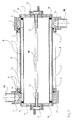
- Figure 2 shows a section through the axis of the reactor. Between the two flanges 1, 2 there are an inner tube 7 and the housing 4, which is designed as an outer tube.
- the tubes 7, 4 delimit the annular gap-shaped reaction space 8, which merges into a displacement gap 13 on both sides.
- the displacement gap 13 is connected via a bore 14 to the inlet 17 and to the outlet 18, respectively.
- the flanges 1, 2 are screwed together with the cross struts 3.
- the rings 5 together with O-rings 9 seal the outer tube 4 against the flanges 1, 2, while the covers 6 together with O-rings 10 seal the inner tube 7 and at the same time close the through holes 15 in the flanges 1, 2.
- Lamp holders 11 are let into the cover 6 by means of a good heat-conducting connection and are fixed with hoods 12.
- the lamp holder 11 encompass the lamp 19 at its base and thereby hold it.
- Figure 3 shows a section perpendicular to the reactor axis through one of the two flanges 1, 2.
- the flanges are identical.
- a bore 14 is shown, which merges into the displacement gap 13.
- the reaction medium enters the displacement gap 13 through the bore 14 and is transferred into the reaction space 8 by the slightly tapering cross section thereof.
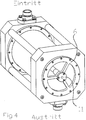
- FIG. 4 shows a further exemplary embodiment which differs from the exemplary embodiment shown in FIG. 1 by a perforated cover 6 '. Such an embodiment is chosen when it is necessary to cool the UV lamp.
- a lamp holder 11 ' can be seen in the center of the cover.
Landscapes
- Chemical & Material Sciences (AREA)
- Toxicology (AREA)
- Organic Chemistry (AREA)
- Health & Medical Sciences (AREA)
- General Health & Medical Sciences (AREA)
- Physics & Mathematics (AREA)
- Electromagnetism (AREA)
- Chemical Kinetics & Catalysis (AREA)
- Life Sciences & Earth Sciences (AREA)
- Hydrology & Water Resources (AREA)
- Engineering & Computer Science (AREA)
- Environmental & Geological Engineering (AREA)
- Water Supply & Treatment (AREA)
- Physical Or Chemical Processes And Apparatus (AREA)
Applications Claiming Priority (2)
| Application Number | Priority Date | Filing Date | Title |
|---|---|---|---|
| DE29607581U DE29607581U1 (de) | 1996-04-26 | 1996-04-26 | UV-Flanschreaktor zur Einstrahlung von ultraviolettem Licht in ein Reaktionsmedium |
| DE29607581U | 1996-04-26 |
Publications (2)
| Publication Number | Publication Date |
|---|---|
| EP0803472A1 true EP0803472A1 (fr) | 1997-10-29 |
| EP0803472B1 EP0803472B1 (fr) | 2000-08-09 |
Family
ID=8023168
Family Applications (1)
| Application Number | Title | Priority Date | Filing Date |
|---|---|---|---|
| EP97106950A Expired - Lifetime EP0803472B1 (fr) | 1996-04-26 | 1997-04-25 | Réacteur à UV pour irradier un milieu réactionnel |
Country Status (4)
| Country | Link |
|---|---|
| EP (1) | EP0803472B1 (fr) |
| AT (1) | ATE195301T1 (fr) |
| DE (2) | DE29607581U1 (fr) |
| ES (1) | ES2148871T3 (fr) |
Cited By (7)
| Publication number | Priority date | Publication date | Assignee | Title |
|---|---|---|---|---|
| DE102008021301A1 (de) | 2008-04-21 | 2009-10-22 | A.C.K. Aqua Concept Gmbh Karlsruhe | UV-Reaktor und seine Verwendung |
| US7651660B2 (en) | 2000-11-13 | 2010-01-26 | Bayer Aktiengesellschaft | Apparatus for irradiating liquids |
| EP2284126A1 (fr) | 2009-08-13 | 2011-02-16 | Koninklijke Philips Electronics N.V. | Dispositif comprenant des moyens pour guider un fluide et une source de radiation UV |
| WO2011156281A1 (fr) * | 2010-06-07 | 2011-12-15 | Genzyme Corporation | Dispositif pour l'inactivation virale de milieux liquides |
| WO2012044264A1 (fr) * | 2010-09-27 | 2012-04-05 | Koepruelue Yusuf Kemal | Procédé destiné à la stérilisation froide et à la pasteurisation de liquides transparents, translucides ou opaques |
| CZ307929B6 (cs) * | 2018-12-20 | 2019-08-28 | Ăšstav hematologie a krevnĂ transfuze | Zařízení pro dezinfekci proudu plynu a způsob validace tohoto zařízení |
| DE102018002089A1 (de) | 2018-03-15 | 2019-09-19 | Jürgen Axmann | UVC-LED-Entkeimungsmodul für flüssige Medien |
Families Citing this family (3)
| Publication number | Priority date | Publication date | Assignee | Title |
|---|---|---|---|---|
| JPH10272459A (ja) * | 1997-03-31 | 1998-10-13 | Power Reactor & Nuclear Fuel Dev Corp | 環境浄化体、環境浄化方法及び環境浄化装置 |
| DE102005056267B4 (de) * | 2005-04-22 | 2013-11-21 | A.C.K. Aqua Concept Gmbh Karlsruhe | Rotierende Reinigungseinrichtung für Strahlerschutzröhren |
| DE102010042670B4 (de) | 2010-10-20 | 2013-07-18 | Umex Gmbh Dresden | Vorrichtung zur UV-Bestrahlung |
Citations (4)
| Publication number | Priority date | Publication date | Assignee | Title |
|---|---|---|---|---|
| DE3117473A1 (de) * | 1981-05-02 | 1982-11-25 | Siegfried 3000 Hannover Paul | Schwimmbecken- und brauchwasser-entkeimungsgeraet |
| JPS62201639A (ja) * | 1986-02-27 | 1987-09-05 | Sumitomo Electric Ind Ltd | 紫外線照射装置 |
| DE3710555A1 (de) * | 1987-03-30 | 1988-11-03 | Ernst Vogel Gmbh | Vorrichtung zur uv-entkeimung von fluessigkeiten |
| DE3924349A1 (de) * | 1989-07-22 | 1991-01-31 | Waterangel Wasseraufbereitungs | Entkeimungsgeraet fuer fluessigkeiten |
-
1996
- 1996-04-26 DE DE29607581U patent/DE29607581U1/de not_active Expired - Lifetime
-
1997
- 1997-04-25 DE DE59702123T patent/DE59702123D1/de not_active Expired - Lifetime
- 1997-04-25 AT AT97106950T patent/ATE195301T1/de active
- 1997-04-25 EP EP97106950A patent/EP0803472B1/fr not_active Expired - Lifetime
- 1997-04-25 ES ES97106950T patent/ES2148871T3/es not_active Expired - Lifetime
Patent Citations (4)
| Publication number | Priority date | Publication date | Assignee | Title |
|---|---|---|---|---|
| DE3117473A1 (de) * | 1981-05-02 | 1982-11-25 | Siegfried 3000 Hannover Paul | Schwimmbecken- und brauchwasser-entkeimungsgeraet |
| JPS62201639A (ja) * | 1986-02-27 | 1987-09-05 | Sumitomo Electric Ind Ltd | 紫外線照射装置 |
| DE3710555A1 (de) * | 1987-03-30 | 1988-11-03 | Ernst Vogel Gmbh | Vorrichtung zur uv-entkeimung von fluessigkeiten |
| DE3924349A1 (de) * | 1989-07-22 | 1991-01-31 | Waterangel Wasseraufbereitungs | Entkeimungsgeraet fuer fluessigkeiten |
Non-Patent Citations (1)
| Title |
|---|
| PATENT ABSTRACTS OF JAPAN vol. 012, no. 056 (C - 477) 19 February 1988 (1988-02-19) * |
Cited By (12)
| Publication number | Priority date | Publication date | Assignee | Title |
|---|---|---|---|---|
| US7651660B2 (en) | 2000-11-13 | 2010-01-26 | Bayer Aktiengesellschaft | Apparatus for irradiating liquids |
| EP2949628A1 (fr) | 2000-11-13 | 2015-12-02 | Bayer Intellectual Property GmbH | Dispositif destine au rayonnement de liquides |
| DE102008021301A1 (de) | 2008-04-21 | 2009-10-22 | A.C.K. Aqua Concept Gmbh Karlsruhe | UV-Reaktor und seine Verwendung |
| EP2284126A1 (fr) | 2009-08-13 | 2011-02-16 | Koninklijke Philips Electronics N.V. | Dispositif comprenant des moyens pour guider un fluide et une source de radiation UV |
| WO2011018735A1 (fr) | 2009-08-13 | 2011-02-17 | Koninklijke Philips Electronics N.V. | Dispositif comprenant des moyens de guidage de fluide d'une entrée vers une sortie |
| US8614424B2 (en) | 2009-08-13 | 2013-12-24 | Koninklijke Philips N.V. | Device comprising means for guiding fluid from an inlet to an outlet |
| WO2011156281A1 (fr) * | 2010-06-07 | 2011-12-15 | Genzyme Corporation | Dispositif pour l'inactivation virale de milieux liquides |
| AU2011265099B2 (en) * | 2010-06-07 | 2015-09-17 | Genzyme Corporation | Device for viral inactivation of liquid media |
| US9441196B2 (en) | 2010-06-07 | 2016-09-13 | Genzyme Corporation | Device for viral inactivation of liquid media |
| WO2012044264A1 (fr) * | 2010-09-27 | 2012-04-05 | Koepruelue Yusuf Kemal | Procédé destiné à la stérilisation froide et à la pasteurisation de liquides transparents, translucides ou opaques |
| DE102018002089A1 (de) | 2018-03-15 | 2019-09-19 | Jürgen Axmann | UVC-LED-Entkeimungsmodul für flüssige Medien |
| CZ307929B6 (cs) * | 2018-12-20 | 2019-08-28 | Ăšstav hematologie a krevnĂ transfuze | Zařízení pro dezinfekci proudu plynu a způsob validace tohoto zařízení |
Also Published As
| Publication number | Publication date |
|---|---|
| DE29607581U1 (de) | 1996-12-05 |
| EP0803472B1 (fr) | 2000-08-09 |
| ATE195301T1 (de) | 2000-08-15 |
| DE59702123D1 (de) | 2000-09-14 |
| ES2148871T3 (es) | 2000-10-16 |
Similar Documents
| Publication | Publication Date | Title |
|---|---|---|
| EP0014427B1 (fr) | Photoréacteur à plusieurs chambres, procédé d'irradiation mettant en oeuvre ce photoréacteur | |
| DE4308839C2 (de) | Vorrichtung zum Mischen von Strömungsmedien | |
| EP1339643B1 (fr) | Utilisation d'un dispositif permettant d'exposer des liquides a des rayonnements | |
| DE2851013C2 (de) | Entkeimungsvorrichtung für strömendes Medium | |
| DE2231868C3 (de) | Zelle zur Duchführung der umgekehrten Osmose | |
| EP0803472A1 (fr) | Réacteur à UV pour irradier un milieu réactionnel | |
| DE2559302C3 (de) | Drehbare Rohrverbindung | |
| DE2423303A1 (de) | Vorrichtung zur abscheidung von epitaktischen schichten auf halbleitersubstraten | |
| WO2001017913A1 (fr) | Appareil de traitement de liquide par aimant permanent | |
| DE10221037A1 (de) | Doppelwandkammer zur UV-Desinfektion von Flüssigkeiten, vorzugsweise von Trink- und /oder Abwasser | |
| DE4138916C2 (de) | Vorrichtung in Modulbauweise zum Behandeln schadstoffbelasteter wäßriger Flüssigkeiten mittels UV-Strahlung | |
| DE2336278C2 (de) | Gas/Flüssigkeits-Trenneinheit | |
| DE2400430A1 (de) | Vorrichtung zum entkeimen von fluessigkeiten und gasen | |
| DE2119872A1 (de) | Leitplatte für Mantel und Rohr wärmeaustauscher | |
| CH620596A5 (en) | Appliance for UV irradiation of flowing media | |
| DE2441224A1 (de) | Thermostatisches dehnstoffelement, insbesondere fuer den gebrauch bei mischbatterien fuer kalt- und warmwasser | |
| DE69300038T2 (de) | Wärmetauscher. | |
| DE102005046809B4 (de) | Vorrichtung zur Behandlung von Flüssigkeiten | |
| DE29704749U1 (de) | UV-Ringreaktor zur Einstrahlung von Licht, insbesondere ultraviolettem Licht in ein Reaktionsmedium | |
| AT83389B (de) | Schleudergebläse oder -pumpe. | |
| DE1551431A1 (de) | Erhitzer | |
| AT341113B (de) | Vorrichtung zum keimtoten in flussigkeiten und gasen | |
| DE2409954C3 (de) | Gleitringdichtung mit einer ein Kühlmedium an den Dichtspalt lenkenden Leitapparatur | |
| DE1917108C (de) | Turbinenstromungsmesser | |
| EP1025048A1 (fr) | Equipement permettant le degermage de l'eau traversant une installation sanitaire |
Legal Events
| Date | Code | Title | Description |
|---|---|---|---|
| PUAI | Public reference made under article 153(3) epc to a published international application that has entered the european phase |
Free format text: ORIGINAL CODE: 0009012 |
|
| AK | Designated contracting states |
Kind code of ref document: A1 Designated state(s): AT BE CH DE ES FI FR GB IT LI |
|
| 17P | Request for examination filed |
Effective date: 19971021 |
|
| 17Q | First examination report despatched |
Effective date: 19971223 |
|
| RAP1 | Party data changed (applicant data changed or rights of an application transferred) |
Owner name: A.C.K. AQUA CONCEPT GMBH KARLSRUHE |
|
| GRAG | Despatch of communication of intention to grant |
Free format text: ORIGINAL CODE: EPIDOS AGRA |
|
| GRAG | Despatch of communication of intention to grant |
Free format text: ORIGINAL CODE: EPIDOS AGRA |
|
| GRAH | Despatch of communication of intention to grant a patent |
Free format text: ORIGINAL CODE: EPIDOS IGRA |
|
| GRAH | Despatch of communication of intention to grant a patent |
Free format text: ORIGINAL CODE: EPIDOS IGRA |
|
| GRAA | (expected) grant |
Free format text: ORIGINAL CODE: 0009210 |
|
| AK | Designated contracting states |
Kind code of ref document: B1 Designated state(s): AT BE CH DE ES FI FR GB IT LI |
|
| PG25 | Lapsed in a contracting state [announced via postgrant information from national office to epo] |
Ref country code: IT Free format text: LAPSE BECAUSE OF FAILURE TO SUBMIT A TRANSLATION OF THE DESCRIPTION OR TO PAY THE FEE WITHIN THE PRESCRIBED TIME-LIMIT;WARNING: LAPSES OF ITALIAN PATENTS WITH EFFECTIVE DATE BEFORE 2007 MAY HAVE OCCURRED AT ANY TIME BEFORE 2007. THE CORRECT EFFECTIVE DATE MAY BE DIFFERENT FROM THE ONE RECORDED. Effective date: 20000809 Ref country code: FI Free format text: LAPSE BECAUSE OF FAILURE TO SUBMIT A TRANSLATION OF THE DESCRIPTION OR TO PAY THE FEE WITHIN THE PRESCRIBED TIME-LIMIT Effective date: 20000809 |
|
| REF | Corresponds to: |
Ref document number: 195301 Country of ref document: AT Date of ref document: 20000815 Kind code of ref document: T |
|
| REG | Reference to a national code |
Ref country code: CH Ref legal event code: NV Representative=s name: RIEDERER HASLER & PARTNER PATENTANWAELTE AG Ref country code: CH Ref legal event code: EP |
|
| GBT | Gb: translation of ep patent filed (gb section 77(6)(a)/1977) |
Effective date: 20000809 |
|
| REF | Corresponds to: |
Ref document number: 59702123 Country of ref document: DE Date of ref document: 20000914 |
|
| ET | Fr: translation filed | ||
| REG | Reference to a national code |
Ref country code: ES Ref legal event code: FG2A Ref document number: 2148871 Country of ref document: ES Kind code of ref document: T3 |
|
| PLBE | No opposition filed within time limit |
Free format text: ORIGINAL CODE: 0009261 |
|
| STAA | Information on the status of an ep patent application or granted ep patent |
Free format text: STATUS: NO OPPOSITION FILED WITHIN TIME LIMIT |
|
| 26N | No opposition filed | ||
| REG | Reference to a national code |
Ref country code: GB Ref legal event code: IF02 |
|
| PGFP | Annual fee paid to national office [announced via postgrant information from national office to epo] |
Ref country code: GB Payment date: 20040413 Year of fee payment: 8 |
|
| PGFP | Annual fee paid to national office [announced via postgrant information from national office to epo] |
Ref country code: ES Payment date: 20040427 Year of fee payment: 8 |
|
| PG25 | Lapsed in a contracting state [announced via postgrant information from national office to epo] |
Ref country code: GB Free format text: LAPSE BECAUSE OF NON-PAYMENT OF DUE FEES Effective date: 20050425 |
|
| PG25 | Lapsed in a contracting state [announced via postgrant information from national office to epo] |
Ref country code: ES Free format text: LAPSE BECAUSE OF NON-PAYMENT OF DUE FEES Effective date: 20050426 |
|
| GBPC | Gb: european patent ceased through non-payment of renewal fee |
Effective date: 20050425 |
|
| REG | Reference to a national code |
Ref country code: ES Ref legal event code: FD2A Effective date: 20050426 |
|
| REG | Reference to a national code |
Ref country code: CH Ref legal event code: PCAR Free format text: RIEDERER HASLER & PARTNER PATENTANWAELTE AG;ELESTASTRASSE 8;7310 BAD RAGAZ (CH) |
|
| REG | Reference to a national code |
Ref country code: DE Ref legal event code: R082 Ref document number: 59702123 Country of ref document: DE Representative=s name: HUWER & PARTNER PATENT- UND RECHTSANWAELTE PAR, DE Ref country code: DE Ref legal event code: R082 Ref document number: 59702123 Country of ref document: DE Representative=s name: PATENTANWAELTE DIMMERLING & HUWER, DE |
|
| REG | Reference to a national code |
Ref country code: FR Ref legal event code: PLFP Year of fee payment: 19 |
|
| PGFP | Annual fee paid to national office [announced via postgrant information from national office to epo] |
Ref country code: CH Payment date: 20150422 Year of fee payment: 19 Ref country code: DE Payment date: 20150430 Year of fee payment: 19 |
|
| PGFP | Annual fee paid to national office [announced via postgrant information from national office to epo] |
Ref country code: AT Payment date: 20150422 Year of fee payment: 19 Ref country code: FR Payment date: 20150422 Year of fee payment: 19 Ref country code: BE Payment date: 20150430 Year of fee payment: 19 |
|
| PG25 | Lapsed in a contracting state [announced via postgrant information from national office to epo] |
Ref country code: BE Free format text: LAPSE BECAUSE OF NON-PAYMENT OF DUE FEES Effective date: 20160430 |
|
| REG | Reference to a national code |
Ref country code: DE Ref legal event code: R119 Ref document number: 59702123 Country of ref document: DE |
|
| REG | Reference to a national code |
Ref country code: CH Ref legal event code: PL |
|
| REG | Reference to a national code |
Ref country code: AT Ref legal event code: MM01 Ref document number: 195301 Country of ref document: AT Kind code of ref document: T Effective date: 20160425 |
|
| REG | Reference to a national code |
Ref country code: FR Ref legal event code: ST Effective date: 20161230 |
|
| PG25 | Lapsed in a contracting state [announced via postgrant information from national office to epo] |
Ref country code: CH Free format text: LAPSE BECAUSE OF NON-PAYMENT OF DUE FEES Effective date: 20160430 Ref country code: FR Free format text: LAPSE BECAUSE OF NON-PAYMENT OF DUE FEES Effective date: 20160502 Ref country code: LI Free format text: LAPSE BECAUSE OF NON-PAYMENT OF DUE FEES Effective date: 20160430 Ref country code: DE Free format text: LAPSE BECAUSE OF NON-PAYMENT OF DUE FEES Effective date: 20161101 |
|
| PG25 | Lapsed in a contracting state [announced via postgrant information from national office to epo] |
Ref country code: AT Free format text: LAPSE BECAUSE OF NON-PAYMENT OF DUE FEES Effective date: 20160425 |