EP0803464A1 - Übertragungsvorrichtung, insbesondere für Fussgänger, zwischen zwei nacheinander in Reihe angeordneten, Förderungselementen, und Fördervorrichtung mit solcher Vorrichtung ausgestattet - Google Patents
Übertragungsvorrichtung, insbesondere für Fussgänger, zwischen zwei nacheinander in Reihe angeordneten, Förderungselementen, und Fördervorrichtung mit solcher Vorrichtung ausgestattet Download PDFInfo
- Publication number
- EP0803464A1 EP0803464A1 EP96401779A EP96401779A EP0803464A1 EP 0803464 A1 EP0803464 A1 EP 0803464A1 EP 96401779 A EP96401779 A EP 96401779A EP 96401779 A EP96401779 A EP 96401779A EP 0803464 A1 EP0803464 A1 EP 0803464A1
- Authority
- EP
- European Patent Office
- Prior art keywords
- plate
- transport
- pedestrians
- transfer element
- support
- Prior art date
- Legal status (The legal status is an assumption and is not a legal conclusion. Google has not performed a legal analysis and makes no representation as to the accuracy of the status listed.)
- Granted
Links
- 230000001133 acceleration Effects 0.000 claims description 16
- 238000005096 rolling process Methods 0.000 claims description 12
- 238000006073 displacement reaction Methods 0.000 claims description 2
- 230000007704 transition Effects 0.000 description 5
- 230000007423 decrease Effects 0.000 description 1
- 208000018883 loss of balance Diseases 0.000 description 1
- 230000000284 resting effect Effects 0.000 description 1
- 238000003466 welding Methods 0.000 description 1
- 238000004804 winding Methods 0.000 description 1
Images

Classifications
-
- B—PERFORMING OPERATIONS; TRANSPORTING
- B66—HOISTING; LIFTING; HAULING
- B66B—ELEVATORS; ESCALATORS OR MOVING WALKWAYS
- B66B1/00—Control systems of elevators in general
- B66B1/02—Control systems without regulation, i.e. without retroactive action
- B66B1/06—Control systems without regulation, i.e. without retroactive action electric
- B66B1/12—Control systems without regulation, i.e. without retroactive action electric with devices, e.g. handles or levers, located at a control station for direct control movements, e.g. electric mining-hoist control systems
-
- B—PERFORMING OPERATIONS; TRANSPORTING
- B66—HOISTING; LIFTING; HAULING
- B66B—ELEVATORS; ESCALATORS OR MOVING WALKWAYS
- B66B29/00—Safety devices of escalators or moving walkways
- B66B29/08—Means to facilitate passenger entry or exit
Definitions
- the present invention relates to a transfer device, in particular for pedestrians, between two transport elements arranged in extension of one another, as well as a pedestrian transporter equipped with such a transfer device.
- Transporters comprising a continuous conveyor belt made of a deformable material or by a succession of elements with a substantially flat transport surface, making it possible to transport pedestrians at a transport speed greater than that of normal pedestrian walking.
- Such conveyors require, between the entrance of the conveyor belt and the fixed entrance floor, an accelerating element making it possible to gradually bring pedestrians from normal walking speed to the higher speed of the conveyor belt and, between exit from the conveyor belt and the fixed exit floor, a decelerating element allowing pedestrians to gradually return to normal walking speed.
- the present invention provides a transfer device between two transport elements and a transporter equipped with such a device, making it possible to eliminate the above drawback of known transporters.
- the transfer device of the invention in particular for pedestrians, between a first transport element and a second transport element arranged in extension of one another, each element comprising a pedestrian transport surface substantially flat and means for moving pedestrians on the transport surface in a longitudinal direction, is characterized in that it comprises a transfer element with a platform, the pedestrian support surface of which is located substantially in the same common plane on the transport surfaces of the two transport elements, comprises rolling means allowing pedestrians to move without friction from the first transport element to the second transport element, or vice versa.
- the transfer element comprises a tooth plate forming a comb respectively engaging in longitudinal grooves of one and / or the other of the transport elements, fixed to the plate of the transfer element and the surface of which d 'pedestrian support, located on the same plane as that of the platform, also consists of rolling means.
- the rolling means comprise balls housed rotating in corresponding blind holes of the plate of the transfer element and of the plate forming a comb by projecting from the plate and the plate forming comb so as to define the abovementioned bearing surfaces of pedestrians.
- the aforementioned balls are held in the corresponding blind holes of the plate of the transfer element by a plate integral with the plate and comprising holes pierced respectively by the balls and of a diameter less than the diameter of the balls and the balls of the comb plate are held in their corresponding blind holes respectively by flat washers with frustoconical central holes.
- the aforementioned rolling means comprise rollers mounted for rotation transversely to the direction of movement of the pedestrians in corresponding approximately semi-cylindrical housings of the plate of the transfer element and of the plate forming a comb by making projection of this plate of this plate so as to define the abovementioned bearing surfaces of pedestrians.
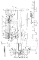
- the plate of the transfer element is on the one hand pivotally supported on a support frame by support legs and on the other fixed to the support frame by two elements forming tie rods situated on each side of the plate. outside the bearing surface thereof so as to allow the tilting of the platform to be adjusted to a position in which the bearing surface of the platform is situated in the plane common to the transport surfaces of the two elements transport.
- the support feet of the tray of the transfer element have their free ends housed respectively in inclined grooves transverse to the longitudinal direction of movement of the pedestrians and produced respectively in support parts integral with the support frame, said transverse grooves allowing transverse displacement by sliding of the transfer element by a small amount, of the order of a few millimeters, when the longitudinal grooves of one and / or the other of the transport elements strike the teeth of the plate forming a comb.
- Each tie-forming element has a threaded end anchored in a threaded hole of a first transverse axis supported by a yoke secured to the plate of the transfer element and its other threaded end passing through a hole in a second transverse axis supported by a yoke secured to a support piece fixed to the support frame, two nuts located on either side of the second transverse axis securing the other threaded end of the drawing element in an axial clearance so as to allow pivoting upwards of the transfer element around the ends of the support legs thereof when an object gets caught between the longitudinal grooves of one or other of the transport elements and the teeth of the comb plate .
- Each support piece of the yoke of the second transverse axis comprises a transverse inclined groove for supporting the end of a support tab of the transfer element.
- the invention also provides a conveyor, in particular for pedestrians, comprising a main transport element of the conveyor belt type extended, at each of its ends, by an element transport capable of functioning as an acceleration or deceleration element between the main transport element and a fixed pedestrian loading or unloading floor, and which is characterized in that it comprises a transfer device as defined above and disposed between the acceleration or deceleration element and the main transport element.
- the transporter of the invention will be described in application to the transport of pedestrians, but it is indeed understood that it can also apply to the transport of objects, such as goods, luggage, etc.
- the conveyor belt shown in Figure 1, arranged between two fixed floors 1, 2, is of the type comprising a substantially planar strip 3 allow to transport pedestrians in the direction indicated by the arrow F that is to say in the direction longitudinal of the strip, and winding on two extreme drums 4, one of which is motor, arranged transversely to the direction of movement of the pedestrians.
- the conveyor belt 3 moves at a higher speed than the normal walking speed of a pedestrian.
- the transporter also includes an acceleration element 5 disposed between the fixed inlet floor 1 and the inlet of the conveyor belt 3 defined relative to the direction of movement of the latter and a deceleration element 6 disposed between the outlet of the conveyor belt 3 and the fixed outlet floor 2 .
- the acceleration or deceleration element is known per se and can be produced as described in document EP-A-0 509 861. More specifically, the acceleration element 5 or the deceleration element 6 comprises series of parallel rollers interlocking with one another so as to constitute a surface for the continuous transport of pedestrians, and means for driving the rollers so that their speed progressively increases by an entry roller for the element d acceleration 5 to a roll of output of this element or gradually decreases from an input roller of the deceleration element 6 to an output roller thereof.
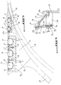
- FIG. 3 schematically represents the acceleration element 5 comprising the rollers 7 nested one inside the other and defining the transport surface S1 of the pedestrians.
- a transfer element 8 is arranged between the acceleration element 5 and the conveyor belt 3 or between the conveyor belt 3 and the deceleration element 6.
- each transfer element 8 comprises a plate 9, the bearing surface S2 of the pedestrians of which is situated substantially in the same plane common to the transport surface S1 of the acceleration element 5 or deceleration element 6 and on the transport surface of the conveyor belt 3 and comprises rolling means 10 allowing the pedestrian movement of the acceleration element 5 practically without friction from the conveyor belt or from the conveyor belt 3 to the deceleration element 6.
- the transfer element 8 comprises a comb plate 11, the teeth 12 of which respectively engage in longitudinal grooves 13 of the conveyor belt 3 defined between ribs 14 of this one.
- the comb plate 11 is fixed to the plate 9 of the transfer element 8, for example by fixing screws 15 and has its pedestrian support surface S3 located in the same plane as the support surface S2 of the plate 9 and also consists of rolling means 16 allowing the movement of pedestrians practically without friction from the plate forming a comb 11 to the conveyor belt 3, or vice versa.
- the rolling means of the plate 9 and of the comb plate 11 consist of balls 10, 16, the balls 10 being housed in corresponding blind holes 17 of the plate 9, while the balls 16 are housed in corresponding blind holes 18 of the comb plate 11 as can be seen better from FIG. 5.
- the balls 10, 16 are held in their respective holes 17, 18 by projecting from the plate 9 and from the plate forming a comb 11 so as to define the bearing surfaces S2 and S3 and rotate on themselves in these housings during the pedestrian crossing.
- the balls 10 are held in their corresponding blind holes 17, produced in a plate 9a attached to the plate 9 of the transfer element 8 and fixed to the latter by screws 9b, by a plate 19 fixed to the plate 9a, for example by fixing screws 20, the plate 19 comprising holes 21 crossed respectively by the balls 10 and of a diameter less than the diameter of the latter.
- the balls 16 are held in the corresponding blind holes 18 of the comb plate 11 respectively by flat washers 22, each housed in a countersink 23 machined in the plate 11, each washer 22 having its frustoconical central hole 22a resting on ball 16.
- the rolling means 10, 16 can be constituted by rollers mounted transversely to the longitudinal direction of the conveyor belt 3 in corresponding approximately semi-cylindrical housings of the plate 9 of the transfer element 8 and the comb plate 11 projecting from the plate 9 and the plate 11 so as to define the bearing surfaces S2 and S3 of the pedestrians.
- the plate 9 of the transfer element 8 is pivotally supported on a support frame 24 by support legs 25 arranged symmetrically to the longitudinal axis XX 'of the strip 3 and whose free ends 25a are housed respectively in inclined grooves 26 respectively of support pieces 27, 28 integral with the chassis 24, the grooves 26 being aligned transversely to the longitudinal axis XX 'of the conveyor belt 3.
- Two support pieces 27 are arranged symmetrically to the longitudinal axis XX ′ of the strip 3 and are fixed to a wing of a cross member 29 in an L inverted by fixing screws 30, the cross member 29 being secured, for example by welding, to the chassis 24.
- each transfer element 8 is bilaterally fixed to the support frame 24 by two tie-rod elements 31 arranged symmetrically to the axis XX 'outside the bearing surface S2 of the plate 9 so as to allow tilt adjustment of this plate to a position according to which the support surface S2 is located in the plane common to the surfaces transporting the acceleration element 5 or deceleration element 6 and the conveyor belt 3, respectively.
- Each drawing element 31, parallel to the axis XX ′, has a threaded end part 31a anchored in a corresponding tapped hole 32a crossing a transverse axis 32 supported by a yoke 33 secured to an end part 9c of the plate 9 of the transfer element 8, which part 9c also includes a support tab 25, the lower free end of which is engaged in the groove 26 of the corresponding support piece 28 fixed to the cross-member 29 by fixing screws (not shown) .
- the drawing element 31 has its other threaded end portion 31b passing through a hole 34a made through another transverse axis 34 supported by a yoke 35 of the support piece 28.
- Two nuts 36, 37 are screwed onto the threaded part 31b of the pulling element 31 on either side of the transverse axis 34 so as to secure this threaded part to the axis 34.
- the nut 37 is not fully tightened against the axis 34 and leaves a clearance j of approximately 2 millimeters so as to allow a slight pivoting of the transfer element 8 around the free ends of the support legs 25 in a direction tending to spread upwards, in view of the Figure 3, the comb plate 11 of the conveyor belt 3.
- Such pivoting occurs when an object gets caught between the longitudinal grooves 13 of the conveyor belt 3 and the teeth 12 of the comb plate 11 and allowing the transport element 8 actuating a contactor element intended to control the stopping of the drive roller 4 for driving the conveyor belt 3.
- the transfer element 8 is held in a fixed position by the tie-rod elements 31 which each comprise a central nut 31c allowing precise adjustment of the position of the bearing surfaces S2 and S3 of the transfer element 8 relative to the transport surfaces of the acceleration element 5 or deceleration element 6 and of the conveyor belt 3.
- FIG. 3 shows that the bearing surfaces S2, S3 of each transfer element 8 can be offset below the transport surface of the conveyor belt 3 to a value of approximately 5 millimeters without an imbalance being inflicted on pedestrians crossing the very small transition zone between the end of the comb plate 11 and the conveyor belt 3.
- each transverse axis 34 is mounted in two oblong holes (not shown) of the yoke 35 extending parallel to the axis XX 'of the conveyor belt 3.
- the transfer device described above of the invention is of an extremely simple structure, does not require any change in level in the transition zone between an acceleration element or a deceleration element and the conveyor belt and allows reversibility operating belt conveyor, that is to say the movement of the conveyor belt can be carried out in one direction or the other.
- the transfer device of the invention can be used in so-called "moving walkways" conveyors, where the conveyor belt is made up of elements which are linked together.
- the transfer device of the invention can be installed between two conveyor belts aligned in extension of one another or offset with respect to each other by forming an angle in which the transfer device would be arranged. , the latter comprising two end plates forming a comb whose teeth are engaged in the longitudinal grooves respectively of the two conveyor belts.
Landscapes
- Engineering & Computer Science (AREA)
- Automation & Control Theory (AREA)
- Escalators And Moving Walkways (AREA)
- Vehicle Cleaning, Maintenance, Repair, Refitting, And Outriggers (AREA)
- Rollers For Roller Conveyors For Transfer (AREA)
Applications Claiming Priority (2)
| Application Number | Priority Date | Filing Date | Title |
|---|---|---|---|
| FR9605109 | 1996-04-23 | ||
| FR9605109A FR2747664B1 (fr) | 1996-04-23 | 1996-04-23 | Dispositif de transfert, en particulier pour pietons, entre deux elements de transport disposes en prolongement l'un de l'autre et transporteur equipe d'un tel dispositif |
Publications (2)
| Publication Number | Publication Date |
|---|---|
| EP0803464A1 true EP0803464A1 (de) | 1997-10-29 |
| EP0803464B1 EP0803464B1 (de) | 2000-11-02 |
Family
ID=9491504
Family Applications (1)
| Application Number | Title | Priority Date | Filing Date |
|---|---|---|---|
| EP96401779A Expired - Lifetime EP0803464B1 (de) | 1996-04-23 | 1996-08-13 | Übertragungsvorrichtung, insbesondere für Fussgänger, zwischen zwei nacheinander in Reihe angeordneten, Förderungselementen, und Fördervorrichtung mit solcher Vorrichtung ausgestattet |
Country Status (7)
| Country | Link |
|---|---|
| US (2) | US5908104A (de) |
| EP (1) | EP0803464B1 (de) |
| JP (1) | JP4015718B2 (de) |
| AT (1) | ATE197284T1 (de) |
| AU (1) | AU724823B2 (de) |
| DE (1) | DE69610817T2 (de) |
| FR (1) | FR2747664B1 (de) |
Cited By (2)
| Publication number | Priority date | Publication date | Assignee | Title |
|---|---|---|---|---|
| CN107074459A (zh) * | 2014-09-25 | 2017-08-18 | 莱特拉姆有限责任公司 | 弹起式输送机传送系统 |
| CN108840083A (zh) * | 2018-07-26 | 2018-11-20 | 张汉军 | 一种长距离传输用传输皮带连接处防打滑传输器 |
Families Citing this family (19)
| Publication number | Priority date | Publication date | Assignee | Title |
|---|---|---|---|---|
| EP0982261A3 (de) * | 1998-08-18 | 2002-02-13 | Masao Kubota | Endloses Fördersystem mit höherer Geschwindigkeit |
| ES2179720B1 (es) | 1999-11-19 | 2004-03-16 | Thyssen Norte S A | Pasillo de aceleracion. |
| US6484869B1 (en) * | 2000-11-14 | 2002-11-26 | Rapistan Systems Advertising Corp. | Conveyor personnel gate |
| FR2851237B1 (fr) * | 2003-02-19 | 2006-04-28 | Mediterranee Const Ind | Dispositif de transfert perfectionne pour systeme de transport, tel que trottoir roulant |
| FI117173B (fi) * | 2003-11-28 | 2006-07-14 | Kone Corp | Liukukäytävä |
| US7210569B1 (en) * | 2004-02-09 | 2007-05-01 | Tarpaulin.Com, Inc. | Transfer device for conveyor belt |
| FI115902B (fi) * | 2004-06-30 | 2005-08-15 | Kone Corp | Liukukäytävä |
| US7111725B2 (en) * | 2004-10-13 | 2006-09-26 | Laitram, L.L.C | Non-skid modular plastic conveyor belt |
| JP5087217B2 (ja) * | 2004-11-08 | 2012-12-05 | インベンテイオ・アクテイエンゲゼルシヤフト | エスカレータまたは動く歩道 |
| ES2281305B1 (es) | 2006-12-28 | 2008-06-01 | Thyssenkrupp Norte, S.A. | Dispositivo de seguridad para sistemas de transporte. |
| US7673732B2 (en) * | 2007-09-28 | 2010-03-09 | Pro Engineering & Manufacturing, Inc. | Transfer plate and method of interfacing to a belt |
| ES2300225B1 (es) * | 2007-11-07 | 2009-08-24 | Thyssenkrupp Elevator (Es/Pbb)Ltd | Pasillo movil. |
| ES2334322B1 (es) * | 2009-07-03 | 2010-12-27 | Tyhssenkrupp Elevator Innovation Center, S.A. | Rampa para transporte de personas y/o mercancias. |
| US8157083B2 (en) * | 2009-12-23 | 2012-04-17 | Laitran, L.L.C. | Self-clearing conveyor transfer system and transfer plate |
| ES2368327B1 (es) * | 2011-07-20 | 2012-09-18 | Thyssenkrupp Elevator Innovation Center, S.A. | Junta longitudinal. |
| CN103935875A (zh) * | 2013-01-18 | 2014-07-23 | 通力股份公司 | 梳齿板-梳齿板托架组件及其与吊装用具的组合结构 |
| WO2017099988A1 (en) | 2015-12-09 | 2017-06-15 | Laitram, L.L.C. | Conveyor transfer assembly |
| KR102039898B1 (ko) * | 2018-02-02 | 2019-11-04 | 대한민국 | 카트충돌 방지용 에스컬레이터 안전장치 |
| US12410038B1 (en) * | 2024-03-06 | 2025-09-09 | Beltways Inc. | Dynamic comb for conveyance systems for moving people or objects |
Citations (6)
| Publication number | Priority date | Publication date | Assignee | Title |
|---|---|---|---|---|
| FR1583906A (de) * | 1968-06-14 | 1969-12-05 | ||
| US3518944A (en) * | 1967-11-20 | 1970-07-07 | Pierre Patin | Steplessly variable-speed conveyor |
| EP0352968A2 (de) * | 1988-07-25 | 1990-01-31 | Loderway Pty. Limited | Ein beweglicher Gehweg |
| EP0509861A1 (de) * | 1991-04-12 | 1992-10-21 | Pierre Patin | Fördereinrichtung, insbesondere mit Hochgeschwindigkeitsförderstrecke |
| FR2693446A1 (fr) * | 1992-03-30 | 1994-01-14 | Dunlop Enerka Bv | Pièce de remplissage. |
| FR2706880A1 (en) * | 1993-06-21 | 1994-12-30 | Montagner Rene | Installation for transporting individuals in an upright position |
Family Cites Families (7)
| Publication number | Priority date | Publication date | Assignee | Title |
|---|---|---|---|---|
| US2624444A (en) * | 1950-02-25 | 1953-01-06 | Jampol Company Inc | Apparatus for free pivoting transfer rollers |
| US3144117A (en) * | 1958-08-12 | 1964-08-11 | Otis Elevator Co | Comb plate for belt type moving sidewalk |
| US3020993A (en) * | 1960-04-05 | 1962-02-13 | Chester J Heinrich | Ball transfer tables |
| US3052337A (en) * | 1960-11-28 | 1962-09-04 | Sr John W Force | Safety landing for moving sidewalk |
| JPH03186590A (ja) * | 1989-12-15 | 1991-08-14 | Kiyoshi Endo | 速度可変エスカレータおよび移動歩道ユニット |
| IT222737Z2 (it) * | 1991-09-19 | 1995-04-24 | Regina Sud Spa | Elemento terminale modulare per trasportatore |
| US5584373A (en) * | 1995-05-26 | 1996-12-17 | Span Tech Corporation | Conveyor system with passive roller transfer assembly |
-
1996
- 1996-04-23 FR FR9605109A patent/FR2747664B1/fr not_active Expired - Fee Related
- 1996-08-13 EP EP96401779A patent/EP0803464B1/de not_active Expired - Lifetime
- 1996-08-13 AT AT96401779T patent/ATE197284T1/de active
- 1996-08-13 DE DE69610817T patent/DE69610817T2/de not_active Expired - Lifetime
- 1996-08-20 US US08/701,349 patent/US5908104A/en not_active Expired - Lifetime
- 1996-08-29 AU AU64361/96A patent/AU724823B2/en not_active Ceased
- 1996-09-20 JP JP25020696A patent/JP4015718B2/ja not_active Expired - Lifetime
-
1999
- 1999-04-22 US US09/296,483 patent/US6068107A/en not_active Expired - Lifetime
Patent Citations (6)
| Publication number | Priority date | Publication date | Assignee | Title |
|---|---|---|---|---|
| US3518944A (en) * | 1967-11-20 | 1970-07-07 | Pierre Patin | Steplessly variable-speed conveyor |
| FR1583906A (de) * | 1968-06-14 | 1969-12-05 | ||
| EP0352968A2 (de) * | 1988-07-25 | 1990-01-31 | Loderway Pty. Limited | Ein beweglicher Gehweg |
| EP0509861A1 (de) * | 1991-04-12 | 1992-10-21 | Pierre Patin | Fördereinrichtung, insbesondere mit Hochgeschwindigkeitsförderstrecke |
| FR2693446A1 (fr) * | 1992-03-30 | 1994-01-14 | Dunlop Enerka Bv | Pièce de remplissage. |
| FR2706880A1 (en) * | 1993-06-21 | 1994-12-30 | Montagner Rene | Installation for transporting individuals in an upright position |
Cited By (3)
| Publication number | Priority date | Publication date | Assignee | Title |
|---|---|---|---|---|
| CN107074459A (zh) * | 2014-09-25 | 2017-08-18 | 莱特拉姆有限责任公司 | 弹起式输送机传送系统 |
| CN108840083A (zh) * | 2018-07-26 | 2018-11-20 | 张汉军 | 一种长距离传输用传输皮带连接处防打滑传输器 |
| CN108840083B (zh) * | 2018-07-26 | 2020-07-28 | 南通澳润建材科技有限公司 | 一种长距离传输用传输皮带连接处防打滑传输器 |
Also Published As
| Publication number | Publication date |
|---|---|
| FR2747664A1 (fr) | 1997-10-24 |
| JP4015718B2 (ja) | 2007-11-28 |
| JPH09286582A (ja) | 1997-11-04 |
| DE69610817D1 (de) | 2000-12-07 |
| ATE197284T1 (de) | 2000-11-15 |
| EP0803464B1 (de) | 2000-11-02 |
| US6068107A (en) | 2000-05-30 |
| AU724823B2 (en) | 2000-09-28 |
| US5908104A (en) | 1999-06-01 |
| FR2747664B1 (fr) | 1998-06-05 |
| DE69610817T2 (de) | 2001-04-26 |
| AU6436196A (en) | 1997-10-30 |
Similar Documents
| Publication | Publication Date | Title |
|---|---|---|
| EP0803464B1 (de) | Übertragungsvorrichtung, insbesondere für Fussgänger, zwischen zwei nacheinander in Reihe angeordneten, Förderungselementen, und Fördervorrichtung mit solcher Vorrichtung ausgestattet | |
| EP1486452A2 (de) | System zum Heben und Stabilisieren von einem hängenden Lastträger | |
| FR2602217A1 (fr) | Convoyeur du genre a accumulation | |
| EP0468841B1 (de) | Bandförderer | |
| FR2517644A1 (fr) | Dispositif pour transporter des objets sur des galets de transport | |
| FR2819497A1 (fr) | Installation pour la circulation de palettes porte-pieces et palette pour cette installation | |
| FR2552063A1 (fr) | Appareil de transport a main courante tel qu'un escalier roulant ou un tapis transporteur | |
| CA2457257C (fr) | Dispositif de transfert perfectionne pour systeme de transport, tel que trottoir roulant | |
| FR2607121A1 (fr) | Convoyeur a accumulation | |
| EP0337891A1 (de) | Stauförderer mit Neigung für einen durch Endlosketten angetriebenen Lastenträger | |
| EP0509861A1 (de) | Fördereinrichtung, insbesondere mit Hochgeschwindigkeitsförderstrecke | |
| EP3100939A1 (de) | Vorrichtung zur spannungseinstellung eines gurtantriebs, insbesondere für eine anwendung an einem fahrrad | |
| EP0449706A1 (de) | Handhabungssystem für Gegenstände | |
| EP1401746A2 (de) | Vorrichtung zum zuführen von teilen zu einer maschine | |
| FR2686041A1 (fr) | Dispositif d'etirage transversal pour la fabrication de films biorientes. | |
| EP0952097B1 (de) | Vorrichtung zur Änderung der Lastverschiebungskonditionen auf einem Rollenförderer | |
| EP0356268B1 (de) | Element in Kurvenform für eine Transferstrasse | |
| EP0330556B1 (de) | Drehscheibe zum Ausstellen eines Kraftfahrzeuges | |
| FR2563817A1 (fr) | Elevateur comportant des godets connectes a des chaines sans fin par des structures de support a trois points | |
| FR2672877A1 (fr) | Tapis transporteur et structure support pour un brin souple, generalement superieur, d'un tel tapis transporteur. | |
| EP0570262B1 (de) | Fördervorrichtung für Lastträger | |
| FR2593477A1 (fr) | Convoyeur a bande | |
| WO1993002953A1 (fr) | Machine de traitement d'objets plats | |
| FR2729357A1 (fr) | Dispositif de freinage pour vehicule ferroviaire | |
| FR2711933A1 (fr) | Magasin à accumulation, notamment pour une chaîne de fabrication ou d'usinage, pour alimenter un poste de travail en pièces ou en outils... . |
Legal Events
| Date | Code | Title | Description |
|---|---|---|---|
| PUAI | Public reference made under article 153(3) epc to a published international application that has entered the european phase |
Free format text: ORIGINAL CODE: 0009012 |
|
| AK | Designated contracting states |
Kind code of ref document: A1 Designated state(s): AT BE CH DE DK ES FI GB GR IE IT LI LU MC NL PT SE |
|
| 17P | Request for examination filed |
Effective date: 19971230 |
|
| GRAG | Despatch of communication of intention to grant |
Free format text: ORIGINAL CODE: EPIDOS AGRA |
|
| 17Q | First examination report despatched |
Effective date: 20000210 |
|
| GRAG | Despatch of communication of intention to grant |
Free format text: ORIGINAL CODE: EPIDOS AGRA |
|
| GRAH | Despatch of communication of intention to grant a patent |
Free format text: ORIGINAL CODE: EPIDOS IGRA |
|
| GRAH | Despatch of communication of intention to grant a patent |
Free format text: ORIGINAL CODE: EPIDOS IGRA |
|
| GRAA | (expected) grant |
Free format text: ORIGINAL CODE: 0009210 |
|
| AK | Designated contracting states |
Kind code of ref document: B1 Designated state(s): AT BE CH DE DK ES FI GB GR IE IT LI LU MC NL PT SE |
|
| PG25 | Lapsed in a contracting state [announced via postgrant information from national office to epo] |
Ref country code: IT Free format text: LAPSE BECAUSE OF FAILURE TO SUBMIT A TRANSLATION OF THE DESCRIPTION OR TO PAY THE FEE WITHIN THE PRESCRIBED TIME-LIMIT;WARNING: LAPSES OF ITALIAN PATENTS WITH EFFECTIVE DATE BEFORE 2007 MAY HAVE OCCURRED AT ANY TIME BEFORE 2007. THE CORRECT EFFECTIVE DATE MAY BE DIFFERENT FROM THE ONE RECORDED. Effective date: 20001102 Ref country code: IE Free format text: LAPSE BECAUSE OF NON-PAYMENT OF DUE FEES Effective date: 20001102 Ref country code: FI Free format text: LAPSE BECAUSE OF FAILURE TO SUBMIT A TRANSLATION OF THE DESCRIPTION OR TO PAY THE FEE WITHIN THE PRESCRIBED TIME-LIMIT Effective date: 20001102 Ref country code: ES Free format text: THE PATENT HAS BEEN ANNULLED BY A DECISION OF A NATIONAL AUTHORITY Effective date: 20001102 |
|
| REF | Corresponds to: |
Ref document number: 197284 Country of ref document: AT Date of ref document: 20001115 Kind code of ref document: T |
|
| REG | Reference to a national code |
Ref country code: CH Ref legal event code: EP |
|
| REF | Corresponds to: |
Ref document number: 69610817 Country of ref document: DE Date of ref document: 20001207 |
|
| REG | Reference to a national code |
Ref country code: IE Ref legal event code: FG4D Free format text: FRENCH |
|
| PG25 | Lapsed in a contracting state [announced via postgrant information from national office to epo] |
Ref country code: SE Free format text: LAPSE BECAUSE OF FAILURE TO SUBMIT A TRANSLATION OF THE DESCRIPTION OR TO PAY THE FEE WITHIN THE PRESCRIBED TIME-LIMIT Effective date: 20010202 Ref country code: PT Free format text: LAPSE BECAUSE OF FAILURE TO SUBMIT A TRANSLATION OF THE DESCRIPTION OR TO PAY THE FEE WITHIN THE PRESCRIBED TIME-LIMIT Effective date: 20010202 Ref country code: DK Free format text: LAPSE BECAUSE OF FAILURE TO SUBMIT A TRANSLATION OF THE DESCRIPTION OR TO PAY THE FEE WITHIN THE PRESCRIBED TIME-LIMIT Effective date: 20010202 |
|
| PG25 | Lapsed in a contracting state [announced via postgrant information from national office to epo] |
Ref country code: GR Free format text: LAPSE BECAUSE OF FAILURE TO SUBMIT A TRANSLATION OF THE DESCRIPTION OR TO PAY THE FEE WITHIN THE PRESCRIBED TIME-LIMIT Effective date: 20010203 |
|
| GBT | Gb: translation of ep patent filed (gb section 77(6)(a)/1977) |
Effective date: 20010112 |
|
| PG25 | Lapsed in a contracting state [announced via postgrant information from national office to epo] |
Ref country code: LU Free format text: LAPSE BECAUSE OF NON-PAYMENT OF DUE FEES Effective date: 20010813 |
|
| REG | Reference to a national code |
Ref country code: IE Ref legal event code: FD4D |
|
| PG25 | Lapsed in a contracting state [announced via postgrant information from national office to epo] |
Ref country code: LI Free format text: LAPSE BECAUSE OF NON-PAYMENT OF DUE FEES Effective date: 20010831 Ref country code: CH Free format text: LAPSE BECAUSE OF NON-PAYMENT OF DUE FEES Effective date: 20010831 Ref country code: BE Free format text: LAPSE BECAUSE OF NON-PAYMENT OF DUE FEES Effective date: 20010831 |
|
| PLBE | No opposition filed within time limit |
Free format text: ORIGINAL CODE: 0009261 |
|
| STAA | Information on the status of an ep patent application or granted ep patent |
Free format text: STATUS: NO OPPOSITION FILED WITHIN TIME LIMIT |
|
| 26N | No opposition filed | ||
| REG | Reference to a national code |
Ref country code: GB Ref legal event code: IF02 |
|
| BERE | Be: lapsed |
Owner name: CONSTRUCTIONS INDUSTRIELLES DE LA MEDITERRANEE- C Effective date: 20010831 |
|
| PG25 | Lapsed in a contracting state [announced via postgrant information from national office to epo] |
Ref country code: MC Free format text: LAPSE BECAUSE OF NON-PAYMENT OF DUE FEES Effective date: 20020301 |
|
| REG | Reference to a national code |
Ref country code: CH Ref legal event code: PL |
|
| PGFP | Annual fee paid to national office [announced via postgrant information from national office to epo] |
Ref country code: AT Payment date: 20110810 Year of fee payment: 16 Ref country code: GB Payment date: 20110810 Year of fee payment: 16 Ref country code: DE Payment date: 20110810 Year of fee payment: 16 |
|
| PGFP | Annual fee paid to national office [announced via postgrant information from national office to epo] |
Ref country code: NL Payment date: 20110818 Year of fee payment: 16 |
|
| REG | Reference to a national code |
Ref country code: NL Ref legal event code: V1 Effective date: 20130301 |
|
| REG | Reference to a national code |
Ref country code: AT Ref legal event code: MM01 Ref document number: 197284 Country of ref document: AT Kind code of ref document: T Effective date: 20120813 |
|
| GBPC | Gb: european patent ceased through non-payment of renewal fee |
Effective date: 20120813 |
|
| PG25 | Lapsed in a contracting state [announced via postgrant information from national office to epo] |
Ref country code: NL Free format text: LAPSE BECAUSE OF NON-PAYMENT OF DUE FEES Effective date: 20130301 |
|
| PG25 | Lapsed in a contracting state [announced via postgrant information from national office to epo] |
Ref country code: AT Free format text: LAPSE BECAUSE OF NON-PAYMENT OF DUE FEES Effective date: 20120813 |
|
| PG25 | Lapsed in a contracting state [announced via postgrant information from national office to epo] |
Ref country code: GB Free format text: LAPSE BECAUSE OF NON-PAYMENT OF DUE FEES Effective date: 20120813 Ref country code: DE Free format text: LAPSE BECAUSE OF NON-PAYMENT OF DUE FEES Effective date: 20130301 |
|
| REG | Reference to a national code |
Ref country code: DE Ref legal event code: R119 Ref document number: 69610817 Country of ref document: DE Effective date: 20130301 |