EP0570262B1 - Fördervorrichtung für Lastträger - Google Patents
Fördervorrichtung für Lastträger Download PDFInfo
- Publication number
- EP0570262B1 EP0570262B1 EP19930401172 EP93401172A EP0570262B1 EP 0570262 B1 EP0570262 B1 EP 0570262B1 EP 19930401172 EP19930401172 EP 19930401172 EP 93401172 A EP93401172 A EP 93401172A EP 0570262 B1 EP0570262 B1 EP 0570262B1
- Authority
- EP
- European Patent Office
- Prior art keywords
- rollers
- support
- axis
- roller
- tubes
- Prior art date
- Legal status (The legal status is an assumption and is not a legal conclusion. Google has not performed a legal analysis and makes no representation as to the accuracy of the status listed.)
- Expired - Lifetime
Links
- 230000007246 mechanism Effects 0.000 claims description 10
- 238000006073 displacement reaction Methods 0.000 claims description 6
- 238000005096 rolling process Methods 0.000 claims description 6
- 230000001360 synchronised effect Effects 0.000 claims description 5
- 230000005540 biological transmission Effects 0.000 claims description 4
- 239000008188 pellet Substances 0.000 claims 1
- 230000008901 benefit Effects 0.000 description 6
- 238000010276 construction Methods 0.000 description 4
- 239000000969 carrier Substances 0.000 description 3
- 230000001133 acceleration Effects 0.000 description 2
- 238000009825 accumulation Methods 0.000 description 2
- 230000000694 effects Effects 0.000 description 2
- 238000003754 machining Methods 0.000 description 2
- 238000000034 method Methods 0.000 description 2
- 230000002829 reductive effect Effects 0.000 description 2
- 230000002441 reversible effect Effects 0.000 description 2
- 230000009471 action Effects 0.000 description 1
- 230000000712 assembly Effects 0.000 description 1
- 238000000429 assembly Methods 0.000 description 1
- 230000000994 depressogenic effect Effects 0.000 description 1
- 238000005265 energy consumption Methods 0.000 description 1
- 238000009434 installation Methods 0.000 description 1
- 230000000670 limiting effect Effects 0.000 description 1
- 238000012423 maintenance Methods 0.000 description 1
- 230000004048 modification Effects 0.000 description 1
- 238000012986 modification Methods 0.000 description 1
- 230000003071 parasitic effect Effects 0.000 description 1
- 230000036961 partial effect Effects 0.000 description 1
- 230000009467 reduction Effects 0.000 description 1
- 230000000717 retained effect Effects 0.000 description 1
Images


Classifications
-
- B—PERFORMING OPERATIONS; TRANSPORTING
- B65—CONVEYING; PACKING; STORING; HANDLING THIN OR FILAMENTARY MATERIAL
- B65G—TRANSPORT OR STORAGE DEVICES, e.g. CONVEYORS FOR LOADING OR TIPPING, SHOP CONVEYOR SYSTEMS OR PNEUMATIC TUBE CONVEYORS
- B65G35/00—Mechanical conveyors not otherwise provided for
- B65G35/06—Mechanical conveyors not otherwise provided for comprising a load-carrier moving along a path, e.g. a closed path, and adapted to be engaged by any one of a series of traction elements spaced along the path
- B65G35/063—Mechanical conveyors not otherwise provided for comprising a load-carrier moving along a path, e.g. a closed path, and adapted to be engaged by any one of a series of traction elements spaced along the path the traction element being a rotating bar or tube
-
- B—PERFORMING OPERATIONS; TRANSPORTING
- B61—RAILWAYS
- B61B—RAILWAY SYSTEMS; EQUIPMENT THEREFOR NOT OTHERWISE PROVIDED FOR
- B61B13/00—Other railway systems
- B61B13/12—Systems with propulsion devices between or alongside the rails, e.g. pneumatic systems
- B61B13/125—Systems with propulsion devices between or alongside the rails, e.g. pneumatic systems the propulsion device being a rotating shaft or the like
Definitions
- the present invention relates to a device for conveying load carriers, for example platforms or pallets.
- conveyors for transporting parts or assemblies of assembled parts between machining or assembly stations. These conveyors all include a guide path for each load support and a mechanism for driving this support along this path.
- Conveyors with rollers or motorized rollers, with friction belong to the group in which the vertical support and the drive of the load are ensured by the same means. Also in this same group, the conveyors in which the load or its support rest on at least one marginal belt which ensures its friction drive, although the support of the load is partly produced by the guide structure.
- the support rolls by means of balls or rollers on the guide track, its drive being carried out by a chain cooperating with a cleat (or a toothed wheel) integral with the support.
- the drive is carried out by friction which allows a disengagement between the motor member in continuous movement and the load support which can or must be immobilized, either in accumulation zones , or in the vicinity of stations served by the conveyor. This declutching leaves a permanent friction force between the drive member and the load support which consumes energy and generates significant wear requiring fairly heavy maintenance of the installation, the efficiency of which is low.
- the present invention intends to improve the efficiency of this type of equipment by proposing a conveyor in which the dissipation of energy by friction is greatly reduced, which is of simple construction and which makes it possible to easily control the acceleration and deceleration of the load support when it is stopped and started.
- the invention therefore relates to a conveyor device for generally flat load carriers, comprising a lateral guide track for each support and a means of driving each support along this track, which comprises two tubes or shafts rotating on themselves and extending along the guide track and at least two drive rollers carried by each load support in a manner known per se, each pivoting about an axis perpendicular to the axis of the tube with the surface of which the roller is in contact.
- This arrangement with two rotating tubes makes it possible to balance the drive forces of the pallet and thus at least partially avoid asymmetrical wear of the elements in movement with respect to each other.
- the rotating tubes can rotate either in the same direction or in opposite directions from one another, the latter possibility making it more complex to produce the means for controlling the pivoting of the drive rollers.
- each pallet or support comprises at least four rollers pivotally mounted around axes perpendicular to this support under the latter to rest in pairs on the upper generator of each of the rotating tubes.
- each support is in the form of a quadrangular pallet and comprises a first group of four rollers pivotally mounted around axes perpendicular to the plane of the pallet and to each of its corners, each roller being doubled along each side of the corresponding corner, with a secondary roller away from the corner roller by a determined value, depending on the width of the interruptions between successive sections of tube or drive axis.
- each roller is pivotally mounted about an axis substantially parallel to the horizontal plane of the support and is applied against the corresponding shaft tube by means of an elastic member, the support having lower rolling members .
- each support comprises a mechanism for synchronized control of the inclination of the rollers around their axis controlled by a push rod movable relative to this support.
- this mechanism comprises a notched pulley integral in rotation with each roller carrier pivoting on the corresponding axis and two notched belts for transmitting these pulleys of the movement generated by the pusher in the form of a double rack meshing with two opposite pinions each integral in rotation with a drive pulley of a belt.
- the mechanism for synchronized control of the inclination of the rollers about their axis comprises a toothed pulley integral in rotation with each pivoting roller holder and a toothed belt for transmitting to all these pulleys a control movement generated by the displacement of one of four movable pushers perpendicular to each edge of the support.
- the mechanism comprises a toothed wheel integral in rotation with each roller carrier pivoting about the corresponding axis and two racks meshing with these wheels and integral with one another and the aforementioned pusher.
- the device according to the invention comprises a fixed frame, the upper part of which determines lateral guide edges for the supports opposite which these supports have lateral rolling rollers.
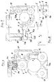
- the load support is represented by a quadrangular pallet 1, equipped at each of its angles with a guide roller 2 mounted rotating around an axis 3 perpendicular to the pallet 1.
- the axis around which the roller 2 is rotatably mounted comprises a fixed part 3a and a movable part 3b in rotation around the part 3a, in the form of a socket, one of which end 4 is in the form of a yoke for rotationally supporting a roller 5.
- the bush 3b is also integral in rotation with a toothed pulley 6, the function of which will be explained below.
- the axial stack formed by this sleeve 3b, the roller 2 and the toothed pulley 6 is pressed against a needle stopper 7 which transmits the load (weight) of the pallet 1 to the roller 4.
- rollers 2 are carried by a corner of the pallet while the axis 3 is located more inside the angle from the palette.
- each pallet has four rollers 2 lateral guide and four rollers 5 by means of which the pallet is driven along a guide path which will be defined later.
- Each roller 5 is in contact, since in this embodiment it is through it that the pallet 1 rests there, with a rotating tube 8, 9.
- the tubes 8 and 9 are of the same diameter and rotate on themselves in opposite directions A and B.
- the rotation of a tube causes the rotation of the roller 5 by friction. If the roller 5 has its plane of rotation perpendicular to the axis of the tube 8, 9 on which it rests, the pallet 1 is stationary along the tubes 8, 9. If on the other hand, according to this known technique, the plane is tilted of rotation of the roller 5 relative to this position perpendicular to the axis of the tube 8, 9, the rotation of the tube 8, 9 causes in addition to the rotation of the roller 5, its displacement relative to the tube 8, 9 along a helix thereof.
- a displacement of the pallet 1 is therefore generated along the axis of the tubes 8, 9.
- the tube 8, 9 is maintained along a guide path defined by a frame 10 whose upper edge 11 cooperates with the side rollers 2 of each pallet, by means of support rollers 12, 13, mounted so as to rotate on the part lower part of this frame 10 substantially perpendicular to the edge 11, so that the upper generatrix of each of the tubes 8, 9 remains completely free so that it can be traversed by the rollers 5.
- the support rollers 12 and 13 are arranged from place to place along the frame 1O shaped profile which has a continuous lower wing 1O a .
- the rollers 12 and 13 are pivotally mounted in a separate housing 1O b which is attached to the frame 1O, in the form of a simpler profile because it has no lower wing.
- Each housing is attached to the section 1O by means of fixing bolts cooperating with the T-grooves of the frame 1O, the shafts 8 and 9 being bordered only by this section without lower wing between the housings.
- This embodiment has the advantage of limiting the areas of the frame where dirt could clump together.
- each housing 10 b advantageously constitutes the connecting piece of the profile with lower support feet.
- the pallets In the particular case of transport of loads on conveyors intended to connect machining or assembly stations of the parts that the pallets 1 carry, the pallets must be stopped either in zones of accumulation of these in determined places of the transporter, or in the vicinity of the stations where operations are carried out.
- This stop is generally controlled by a fixed obstacle which is located along the guide track and which acts on a pusher 14 projecting from the front edge 15 of a pallet 1 moving in the direction C.
- the cooperating obstacle with the pusher 14 can simply be a previous pallet itself stopped along the guide track.
- the pusher 14 has at least one part 14a in the form of a double rack meshing with two toothed wheels 16, 17, locked in rotation on toothed pulleys 18, 19.
- a toothed belt 2O, 21 transmits the angular displacement of each of the toothed pulleys 18, 19 under the effect of the actuation of the pusher 14 to each of the toothed pulleys 6 that has the socket 3b previously described.
- the return strand of each of these belts 20, 21 passes over a pulley 22, 23 which acts as a tensioner for each of them.
- FIG. 2 the pusher is shown in its depressed position up to a stop not shown, which has made it possible to place the plane of rotation of each of the rollers 5 perpendicular to the axis of the tubes 8 and 9.
- the rotation on them -same of these tubes therefore generates no effort tending to move the pallet 1, and the energy consumption is extremely reduced since the rollers 5 roll without rubbing on the tubes 8 and 9.
- the reverse rotation of the tubes 8 and 9 makes it possible to balance the lateral forces which necessarily arise between the tubes and the rollers, this to the advantage of the edges 11 which are only little used to guide the pallet 1. Furthermore , the advantage of this arrangement in which the tubes 8 and 9 are also carriers of the pallet 1, resides in the fact that the more the pallet is loaded and the higher the friction forces between the tubes 8 and 9 and the rollers 5 ; the propelling force advantageously varies in the same direction as the load of the pallet.
- each of the drive rollers 5 arranged at a corner of the pallet is paired with a roller 5 a along one side of the corner and with a roller 5 b along the other side.
- the distance L which separates the axes 3 a of pivoting of these rollers is defined as a function of the intervals separating two consecutive sections of tube along the guide track. For reasons explained below, this distance will be at least equal to the diameter of one of the tubes 8 or 9 increased by the diameter of each roller 5, 5 a , 5 b .
- the lateral rollers 2 which bear on the lateral guide bank 11 are, in this variant, arranged at the level of the drive rollers 5, 5 a , 5 b , and are mounted for rotation directly on the part 4 in the form of a yoke whose outer surface is cylindrical. Above these lateral rollers (which are ball bearings) the toothed pulley 6 is locked in rotation on the assembly 3 a , 4 and cooperates in the transmission of the vertical forces towards the pallet 1 by means of a stop 7 was no longer needle but bearing.
- FIGS. 5 and 6 a first section of track is shown, materialized by the rotating shafts 8 and 9 and the guide edges 11.
- a second section of guideway, perpendicular to the first, is materialized by the sections of tubes 24 a , 25 a , 26 a and 24 b , 25 b , 26 b and sections of banks 27 a , 28 a , 29 a and 27 b , 28 b and 29 b .
- the sections of tubes and edges are separated by a distance slightly greater than the value of the diameter of a tube.
- the pallet 1 is moreover equipped with four pushers 3O which are either in the form of a simple rack to mesh each with a toothed wheel secured to a toothed pulley 31 as in the example described above, or directly fixed to a single belt 32 on a strand thereof constant direction between two toothed pulleys 31.
- the belt 32 is therefore unique and cooperates from the outside with each of the toothed pulleys 6 of each roller 5, 5 a , 5 b , and passes over toothed pulleys 33 and 34 some of which serve to tighten the belt.
- all the rollers 5, 5 a , 5 b are pivoted in the same direction and with the same amplitude.
- This arrangement of synchronized control of the orientation of the rollers implies that the shafts 8 and 9 and the sections of shafts or tubes of the perpendicular track no longer rotate in opposite directions but in the same direction.
- a second action on the pushers 30 inclines the rollers on the axis sections of tubes 25 a , b which are motorized, are then driven in rotation.
- the pallet can then progress in direction D, the roller 5 of FIG. 5 reaching the tube section 26 a before the roller 5 a has left the tube section 25 a .
- FIGS. 7 and 8 we find some of the arrangements already described with reference to the previous figures with the same references. Unlike the variant embodiments already described, that which is illustrated in FIGS. 7 and 8 distinguishes the means for vertical support of the pallet from those for its drive.
- the pallet 1 is equipped with lower rolling members 124 which cooperate with a lower surface 125 secured to the frame 1O.
- Each roller 5 is then pivotally mounted about a horizontal axis 126 and biased against each tube such as 8 by a return spring 127.
- the force exerted by the roller 5 against the tube 8 is collected by the support rollers 12 and 128 carried perpendicular to each other by the frame 1O.
- the direction of inclination of the plane of rotation of the rollers 5 relative to the tubes 8 and 9 is identical, taking into account the fact that the tubes rotate in opposite directions and that the rollers 5 cooperate with opposite generators when passing from one tube to another.
- This type of conveyor is intended for the case where it is necessary to transmit to the pallet 1 a driving force which is independent of its load.
- One will also choose a direction of rotation of the tubes 8 and 9 so that with the inclination of the plane of rotation of the rollers 5, the tangential force therefore vertical between the tubes 8 and 9 and the rollers 5 is directed downwards. to avoid lifting a pallet 1 that is too light or too lightly loaded.
Landscapes
- Engineering & Computer Science (AREA)
- Mechanical Engineering (AREA)
- Chemical & Material Sciences (AREA)
- Combustion & Propulsion (AREA)
- Transportation (AREA)
- Rollers For Roller Conveyors For Transfer (AREA)
Claims (20)
- Fördervorrichtung für im allgemeinen ebene Lastträger, umfassend eine seitliche Führungsbahn (10) für jeden Träger (1) und eine Einrichtung (8,9) für den Antrieb eines jeden Trägers entlang dieser Bahn, dadurch gekennzeichnet, daß die Antriebseinrichtung zwei selbstdrehende und sich entlang der Führungsbahn (10) erstreckende Rohre oder Wellen (8,9) und wenigstens zwei Antriebsrollen (5) umfaßt, die in an sich bekannter Weise an jedem Lastträger (1) derart gehalten sind, daß sie um ein Achse (3) schwenkbar sind, die senkrecht zur Achse des Rohres (8,9) angeordnet ist, mit dessen Oberfläche sich die Rolle in Kontakt befindet.
- Fördervorrichtung nach Anspruch 1, dadurch gekennzeichnet, daß jeder Träger (1) wenigstens vier Rollen (5) aufweist, die unter dem Träger schwenkbar um sich senkrecht zu dem Träger erstreckende Achsen (3) derart gelagert sind, daß sie paarweise auf der oberen Erzeugenden eines jeden sich drehenden Rohres (8,9) lasten.
- Vorrichtung nach Anspruch 1 oder 2, dadurch gekennzeichnet, daß sich die selbstdrehenden Rohre oder Wellen (8,9) gegensinnig drehen.
- Vorrichtung nach Anspruch 3, dadurch gekennzeichnet, daß jeder Träger (1) einen Mechanismus (14) zur Synchronsteuerung der Neigung der Rollen (5) um ihre Achse (3) hat, wobei dieser Mechanismus eine verzahnte Riemenscheibe (18) umfaßt, die drehbar mit jedem um die entsprechende Achse (3) schwenkbaren Rollenhalter (3b,4) verbunden ist, und zwei Zahnriemen (20,21) zur Übertragung einer Steuerbewegung, die durch die Verstellung eines an der Vorderseite jedes Träges (1) angeordneten mobilen Drückers (14) bewirkt wird, auf diese Riemenscheiben (6).
- Vorrichtung nach Anspruch 4, dadurch gekennzeichnet, daß der Drücker (14) in Form einer Doppelzahnstange vorgesehen ist, die mit zwei einander gegenüberliegenden Ritzeln (16,17) in Eingriff steht, deren jedes mit einer Riemenscheibe (18,19) für den Antrieb eines Zahnriemens (20,21) drehbar verbunden ist.
- Vorrichtung nach Anspruch 5, dadurch gekennzeichnet, daß der Drücker (14) der Wirkung einer Rückstellfeder ausgesetzt ist, die versucht, den Drücker in eine Ausgangsposition zu placieren, die einer Neigung der Antriebsrollen (5) dergestalt entspricht, daß ihre Rotationsebene nicht senkrecht zur Achse der sich drehenden Rohre (8,9) liegt.
- Vorrichtung nach Anspruch 2, dadurch gekennzeichnet, daß sich die selbstdrehenden Rohre oder Wellen (8,9) gleichsinnig drehen.
- Vorrichtung nach einem der Ansprüche 1, 2, 3 und 7, dadurch gekennzeichnet, daß jeder Träger die Form einer viereckigen Palette hat und eine erste Gruppe von vier Rollen aufweist, die schwenkbar um zur Palettenebene senkrechte Achsen (3) gelagert sind, und daß jede Eckrolle des Trägers entlang jeder Seite der entsprechenden Ecke um eine zweite Rolle verstärkt ist, die von der Eckrolle um einen Wert beabstandet ist, der in Abhängigkeit von der Größe der Unterbrechungen zwischen aufeinanderfolgenden Rohr- oder Antriebsachsenabschnitten bestimmt wird.
- Vorrichtung nach Anspruch 8, dadurch gekennzeichnet, daß jeder Träger einen Mechanismus zur Synchronsteuerung der Neigung der Rollen um ihre Achse aufweist, wobei dieser Mechanismus eine mit jedem schwenkbaren Rollenhalter drehbar verbundene verzahnte Riemenscheibe und einen Zahnriemen umfaßt, der eine Steuerbewegung, die durch die Verstellung eines von vier senkrecht zu jedem Rand des Trägers angeordneten mobilen Drückern bewirkt wird, auf all diese Riemenscheiben überträgt.
- Vorrichtung nach Anspruch 9, dadurch gekennzeichnet, daß jeder Drücker in Form einer Zahnstange vorgesehen ist, die mit einem Ritzel in Eingriff steht, das mit einer Riemenscheibe für den Antrieb des Riemens drehbar verbunden ist.
- Vorrichtung nach einem der Ansprüche 1 bis 10, dadurch gekennzeichnet, daß die Führungsbahn (10) wenigstens zwei zueinander senkrechte und auf unterschiedlichen Ebenen liegende Abschnitte und wenigstens ein Hebemodul umfaßt, welches zwei Antriebswellenabschnitte hat, die senkrecht zu den Antriebswellen des unteren Abschnitts der Bahn angeordnet sind und vertikal zwischen einer inaktiven Position, in der sie sich unter der Ebene der Wellen des unteren Bahnabschnitts befinden, und einer Position, in der sie mit den Achsen des oberen Bahnabschnitts fluchten, bewegbar sind.
- Vorrichtung nach Anspruch 11, dadurch gekennzeichnet, daß der Abstand, der die Schwenkachse jeder Antriebsrolle von der einen oder anderen ihr benachbarten Rolle trennt, zumindest gleich groß ist wie der um den Wert des Durchmessers einer Rolle vergrößerte Durchmesser eines Antriebsrohres.
- Vorrichtung nach Anspruch 1, dadurch gekennzeichnet, daß jede Rolle (5) um eine zu dem Träger (1) im wesentlichen parallele Achse (26) schwenkbar gelagert ist und über ein elastisches Organ (27) an dem entsprechenden Rohr oder der Welle (8,9) anliegt, wobei der Träger mit unteren Rollkörpern (24) versehen ist.
- Vorrichtung nach Anspruch 1, dadurch gekennzeichnet, daß jeder Träger (1) einen Mechanismus zur Änderung der Neigung der Rollen (5) relativ zur Achse der Rohre (8,9) aufweist, wobei dieser Mechanismus ein mit jedem um die entsprechende Achse schwenkbaren Rollenhalter (4) drehbar verbundenes Zahnrad (29) und zwei Zahnstangen (30) umfaßt, die mit diesen Rädern (29) in Eingriff stehen und miteinander verbunden sind und einen Drücker (14) haben, der sich an der Vorderseite der Palette befindet und gegen die Wirkung eines elastischen Rückstellorgans (32) relativ zu der Palette bewegbar ist.
- Vorrichtung nach einem der vorhergehenden Ansprüche, gekennzeichnet durch ein festes Gestell (10), dessen oberer Bereich seitliche Führungsränder (11) für die Träger (1) bestimmt, wobei diese Träger den seitlichen Führungsrändern gegenüberstehende seitliche Transportrollen (2) besitzen.
- Vorrichtung nach Anspruch 15, dadurch gekennzeichnet, daß die seitlichen Rollen um die Antriebsrollen angeordnet sind.
- Vorrichtung nach Anspruch 13 und 15, dadurch gekennzeichnet, daß das Gestell (10) zwischen den seitlichen Rändern eine untere Transportfläche (25) für die unteren Organe (24) des Trägers (1) aufweist.
- Vorrichtung nach einem der vorhergehenden Ansprüche, dadurch gekennzeichnet, daß die sich drehenden Wellen oder Rohre (8,9) durch Schlepprollen (12,13,28) gehalten sind, die an einem unter den Führungsrändern (11) gelegenen unteren Bereich des Gestells (10) drehbar gelagert sind.
- Vorrichtung nach einem der vorhergehenden Ansprüche, dadurch gekennzeichnet, daß die sich drehenden Wellen oder Rohre (8,9) durch Schlepprollen (12,13,28) gehalten sind, die drehbar in einem Gehäuse (10a) gelagert sind, das unter den Führungsrändern (11) an einem unteren Bereich des Gestells (10) angebracht ist.
- Vorrichtung nach Anspruch 19, dadurch gekennzeichnet, daß jedes Gehäuse (10a) ein Verbindungsteil zwischen dem Gestell der Führungsbahn und einem Fuß des Trägers bildet.
Applications Claiming Priority (2)
| Application Number | Priority Date | Filing Date | Title |
|---|---|---|---|
| FR9205730A FR2691137A1 (fr) | 1992-05-12 | 1992-05-12 | Dispositif de convoyage de supports de charges. |
| FR9205730 | 1992-05-12 |
Publications (2)
| Publication Number | Publication Date |
|---|---|
| EP0570262A1 EP0570262A1 (de) | 1993-11-18 |
| EP0570262B1 true EP0570262B1 (de) | 1996-02-28 |
Family
ID=9429694
Family Applications (1)
| Application Number | Title | Priority Date | Filing Date |
|---|---|---|---|
| EP19930401172 Expired - Lifetime EP0570262B1 (de) | 1992-05-12 | 1993-05-06 | Fördervorrichtung für Lastträger |
Country Status (4)
| Country | Link |
|---|---|
| EP (1) | EP0570262B1 (de) |
| DE (1) | DE69301629T2 (de) |
| ES (1) | ES2085735T3 (de) |
| FR (1) | FR2691137A1 (de) |
Families Citing this family (2)
| Publication number | Priority date | Publication date | Assignee | Title |
|---|---|---|---|---|
| SE512725C2 (sv) | 1998-12-07 | 2000-05-02 | Ocs Overhead Conveyor Sys Ab | Hängtransportsystem |
| EP1935812A1 (de) * | 2006-12-19 | 2008-06-25 | OCS Overhead Conveyor System Aktiebolag | Pufferanordnung für ein Hängefördersystem |
Family Cites Families (6)
| Publication number | Priority date | Publication date | Assignee | Title |
|---|---|---|---|---|
| SE336593B (de) * | 1964-05-11 | 1971-07-12 | Borgs Fabriks Ab | |
| JPS5695965U (de) * | 1979-12-21 | 1981-07-30 | ||
| DE3218012A1 (de) * | 1982-05-13 | 1983-11-24 | Mannesmann AG, 4000 Düsseldorf | Foerderer mit einer rotierend angetriebenen welle |
| NL8202528A (nl) * | 1982-06-22 | 1984-01-16 | Nederlanden Staat | Transportstelsel voor wagentjes. |
| DE3733585C1 (de) * | 1987-10-03 | 1989-01-19 | Albert Zimmer | Transportsystem fuer Montagetransferstrassen |
| DE3912120C2 (de) * | 1989-04-13 | 1996-09-26 | Miele & Cie | Transportsystem für Paletten |
-
1992
- 1992-05-12 FR FR9205730A patent/FR2691137A1/fr active Pending
-
1993
- 1993-05-06 EP EP19930401172 patent/EP0570262B1/de not_active Expired - Lifetime
- 1993-05-06 DE DE1993601629 patent/DE69301629T2/de not_active Expired - Fee Related
- 1993-05-06 ES ES93401172T patent/ES2085735T3/es not_active Expired - Lifetime
Also Published As
| Publication number | Publication date |
|---|---|
| EP0570262A1 (de) | 1993-11-18 |
| FR2691137A1 (fr) | 1993-11-19 |
| DE69301629D1 (de) | 1996-04-04 |
| DE69301629T2 (de) | 1996-10-02 |
| ES2085735T3 (es) | 1996-06-01 |
Similar Documents
| Publication | Publication Date | Title |
|---|---|---|
| FR2480631A1 (fr) | Procede de tri ou de transport et installation et chariot pour sa mise en oeuvre | |
| FR2549450A1 (fr) | Unite d'entrainement par rouleaux, notamment pour le deplacement d'objets sur une bande convoyeuse | |
| EP0803464B1 (de) | Übertragungsvorrichtung, insbesondere für Fussgänger, zwischen zwei nacheinander in Reihe angeordneten, Förderungselementen, und Fördervorrichtung mit solcher Vorrichtung ausgestattet | |
| FR2725708A1 (fr) | Chariot destine a etre suspendu et a se deplacer sur un rail | |
| FR2530590A1 (fr) | Convoyeur helicoidal a rouleaux coniques entraines par courroie | |
| FR2860506A1 (fr) | Transporteur du type a chariot entraine par friction | |
| FR2725428A1 (fr) | Transporteur pousseur a palettes | |
| FR2819497A1 (fr) | Installation pour la circulation de palettes porte-pieces et palette pour cette installation | |
| FR2686592A1 (fr) | Appareil pour desservir des rayonnages. | |
| EP0509861B1 (de) | Fördereinrichtung, insbesondere mit Hochgeschwindigkeitsförderstrecke | |
| FR2607121A1 (fr) | Convoyeur a accumulation | |
| EP0570262B1 (de) | Fördervorrichtung für Lastträger | |
| EP0506551B1 (de) | Speicherförderer | |
| EP1401746B1 (de) | Vorrichtung zum zuführen von teilen zu einer maschine | |
| BE666500A (de) | ||
| EP0449706A1 (de) | Handhabungssystem für Gegenstände | |
| EP0356268B1 (de) | Element in Kurvenform für eine Transferstrasse | |
| EP0952097B1 (de) | Vorrichtung zur Änderung der Lastverschiebungskonditionen auf einem Rollenförderer | |
| EP0190950B1 (de) | Kettenförderer mit Staumöglichkeit von Schlitten auf der Umlaufbahn | |
| FR2719832A1 (fr) | Plateau pour transporteur de type magasin à accumulation. | |
| FR2639039A1 (fr) | Dispositif de convoyage a palettes | |
| EP0223683A1 (de) | Vorrichtung zum Zusammenbau und/oder Gebrauch von Teilen, die von Paletten getragen werden sowie Palette für eine solche Vorrichtung | |
| EP0013531A1 (de) | Rollgang für die Handhabung von Waren | |
| FR2755679A1 (fr) | Dispositif de transport de produits a convoyeurs | |
| EP0323953A1 (de) | Handhabungssystem zum schnellen fördern von schlittenträgern |
Legal Events
| Date | Code | Title | Description |
|---|---|---|---|
| PUAI | Public reference made under article 153(3) epc to a published international application that has entered the european phase |
Free format text: ORIGINAL CODE: 0009012 |
|
| 17P | Request for examination filed |
Effective date: 19930507 |
|
| AK | Designated contracting states |
Kind code of ref document: A1 Designated state(s): BE DE ES GB IT |
|
| 17Q | First examination report despatched |
Effective date: 19941004 |
|
| GRAA | (expected) grant |
Free format text: ORIGINAL CODE: 0009210 |
|
| AK | Designated contracting states |
Kind code of ref document: B1 Designated state(s): BE DE ES GB IT |
|
| GBT | Gb: translation of ep patent filed (gb section 77(6)(a)/1977) |
Effective date: 19960226 |
|
| REF | Corresponds to: |
Ref document number: 69301629 Country of ref document: DE Date of ref document: 19960404 |
|
| ITF | It: translation for a ep patent filed | ||
| REG | Reference to a national code |
Ref country code: ES Ref legal event code: FG2A Ref document number: 2085735 Country of ref document: ES Kind code of ref document: T3 |
|
| PLBE | No opposition filed within time limit |
Free format text: ORIGINAL CODE: 0009261 |
|
| STAA | Information on the status of an ep patent application or granted ep patent |
Free format text: STATUS: NO OPPOSITION FILED WITHIN TIME LIMIT |
|
| 26N | No opposition filed | ||
| PGFP | Annual fee paid to national office [announced via postgrant information from national office to epo] |
Ref country code: GB Payment date: 19970410 Year of fee payment: 5 |
|
| PGFP | Annual fee paid to national office [announced via postgrant information from national office to epo] |
Ref country code: BE Payment date: 19970417 Year of fee payment: 5 |
|
| PGFP | Annual fee paid to national office [announced via postgrant information from national office to epo] |
Ref country code: DE Payment date: 19970510 Year of fee payment: 5 |
|
| PGFP | Annual fee paid to national office [announced via postgrant information from national office to epo] |
Ref country code: ES Payment date: 19970519 Year of fee payment: 5 |
|
| PG25 | Lapsed in a contracting state [announced via postgrant information from national office to epo] |
Ref country code: GB Free format text: LAPSE BECAUSE OF NON-PAYMENT OF DUE FEES Effective date: 19980506 |
|
| PG25 | Lapsed in a contracting state [announced via postgrant information from national office to epo] |
Ref country code: ES Free format text: LAPSE BECAUSE OF EXPIRATION OF PROTECTION Effective date: 19980507 |
|
| PG25 | Lapsed in a contracting state [announced via postgrant information from national office to epo] |
Ref country code: BE Free format text: LAPSE BECAUSE OF NON-PAYMENT OF DUE FEES Effective date: 19980531 |
|
| BERE | Be: lapsed |
Owner name: RENAULT AUTOMATION Effective date: 19980531 |
|
| GBPC | Gb: european patent ceased through non-payment of renewal fee |
Effective date: 19980506 |
|
| PG25 | Lapsed in a contracting state [announced via postgrant information from national office to epo] |
Ref country code: DE Free format text: LAPSE BECAUSE OF NON-PAYMENT OF DUE FEES Effective date: 19990302 |
|
| REG | Reference to a national code |
Ref country code: ES Ref legal event code: FD2A Effective date: 20010201 |
|
| PG25 | Lapsed in a contracting state [announced via postgrant information from national office to epo] |
Ref country code: IT Free format text: LAPSE BECAUSE OF NON-PAYMENT OF DUE FEES;WARNING: LAPSES OF ITALIAN PATENTS WITH EFFECTIVE DATE BEFORE 2007 MAY HAVE OCCURRED AT ANY TIME BEFORE 2007. THE CORRECT EFFECTIVE DATE MAY BE DIFFERENT FROM THE ONE RECORDED. Effective date: 20050506 |