EP0803406A2 - Dispositif de transmission de signaux entre deux terminaux - Google Patents
Dispositif de transmission de signaux entre deux terminaux Download PDFInfo
- Publication number
- EP0803406A2 EP0803406A2 EP97400871A EP97400871A EP0803406A2 EP 0803406 A2 EP0803406 A2 EP 0803406A2 EP 97400871 A EP97400871 A EP 97400871A EP 97400871 A EP97400871 A EP 97400871A EP 0803406 A2 EP0803406 A2 EP 0803406A2
- Authority
- EP
- European Patent Office
- Prior art keywords
- cassette
- steering wheel
- steering column
- end points
- steering
- Prior art date
- Legal status (The legal status is an assumption and is not a legal conclusion. Google has not performed a legal analysis and makes no representation as to the accuracy of the status listed.)
- Granted
Links
- 230000008054 signal transmission Effects 0.000 claims abstract description 5
- 230000013011 mating Effects 0.000 claims abstract description 3
- 239000004020 conductor Substances 0.000 claims description 6
- 230000005540 biological transmission Effects 0.000 description 3
- 238000009434 installation Methods 0.000 description 2
- 238000004804 winding Methods 0.000 description 2
- 238000011990 functional testing Methods 0.000 description 1
- 230000000717 retained effect Effects 0.000 description 1
Images

Classifications
-
- B—PERFORMING OPERATIONS; TRANSPORTING
- B60—VEHICLES IN GENERAL
- B60R—VEHICLES, VEHICLE FITTINGS, OR VEHICLE PARTS, NOT OTHERWISE PROVIDED FOR
- B60R16/00—Electric or fluid circuits specially adapted for vehicles and not otherwise provided for; Arrangement of elements of electric or fluid circuits specially adapted for vehicles and not otherwise provided for
- B60R16/02—Electric or fluid circuits specially adapted for vehicles and not otherwise provided for; Arrangement of elements of electric or fluid circuits specially adapted for vehicles and not otherwise provided for electric constitutive elements
- B60R16/023—Electric or fluid circuits specially adapted for vehicles and not otherwise provided for; Arrangement of elements of electric or fluid circuits specially adapted for vehicles and not otherwise provided for electric constitutive elements for transmission of signals between vehicle parts or subsystems
- B60R16/027—Electric or fluid circuits specially adapted for vehicles and not otherwise provided for; Arrangement of elements of electric or fluid circuits specially adapted for vehicles and not otherwise provided for electric constitutive elements for transmission of signals between vehicle parts or subsystems between relatively movable parts of the vehicle, e.g. between steering wheel and column
-
- B—PERFORMING OPERATIONS; TRANSPORTING
- B60—VEHICLES IN GENERAL
- B60R—VEHICLES, VEHICLE FITTINGS, OR VEHICLE PARTS, NOT OTHERWISE PROVIDED FOR
- B60R16/00—Electric or fluid circuits specially adapted for vehicles and not otherwise provided for; Arrangement of elements of electric or fluid circuits specially adapted for vehicles and not otherwise provided for
- B60R16/02—Electric or fluid circuits specially adapted for vehicles and not otherwise provided for; Arrangement of elements of electric or fluid circuits specially adapted for vehicles and not otherwise provided for electric constitutive elements
- B60R16/03—Electric or fluid circuits specially adapted for vehicles and not otherwise provided for; Arrangement of elements of electric or fluid circuits specially adapted for vehicles and not otherwise provided for electric constitutive elements for supply of electrical power to vehicle subsystems or for
- B60R16/0315—Electric or fluid circuits specially adapted for vehicles and not otherwise provided for; Arrangement of elements of electric or fluid circuits specially adapted for vehicles and not otherwise provided for electric constitutive elements for supply of electrical power to vehicle subsystems or for using multiplexing techniques
Definitions
- the invention relates to a device for signal transmission between two end points, between which an electrical line running in turns and housed in an essentially circular cassette is arranged, to which further lines can be connected at the two end points and whose length is substantially greater than the distance of the two end points is at each other, in which at least one of the two end points is movable relative to the other and in which the cassette consists of two parts, a rotatable about the axis of the cassette, connectable to a steering wheel belonging to the steering column of a motor vehicle and a fixed rotor , Stator connectable to a steering column of the steering column, between which the line is arranged (DE-A-4 216 526).
- Such a device is required for the transmission of a signal for triggering the "airbag” of an impact protection for motor vehicles. It is accommodated in the handlebar arrangement of a motor vehicle for the transmission of an electrical signal.
- a major problem for this device is the signal transmission between fixed and moving parts of the motor vehicle.
- the sliding contacts or slip rings which have long been known for such cases and are used for power transmission, are subject to wear and tear, particularly at low ones Amperages disadvantageous because of the fluctuating contact resistance.
- the invention has for its object to design the device described above so that the assembly of the cassette and steering wheel are simplified.
- the cassette is mounted on the steering wheel before it is placed on the steering column of the steering column.
- the rotor and stator can be rotated relative to one another within narrow limits. This is an advantage when placing the steering wheel on the steering column, so that the two parts of the connector can be easily plugged together. These two parts are connected to one another in a snap-in manner, so that a stable electrical connection is established between the line of the cassette and a further line which is attached in the steering column. The connection is also maintained if the steering wheel - after a functional test for the airbag connection has already been carried out - is lifted a short distance from the steering column of the steering column for final adjustment.
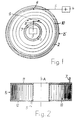
- Fig. 1 two walls 1 and 2 of a cassette K, for example, circular are shown schematically. It is intended for installation in the handlebar arrangement of a motor vehicle.
- the cassette K is connected to the battery 4 of the motor vehicle.
- the battery 4 is connected via an electrical line 5 to a terminal 6 of the cassette K designed as a fixed point.
- the electronics 3 is connected via an electrical line 7 to an end point 8 of the cassette K, which can be moved in the direction of the double arrow 9.
- the terminal 8 could also be fixed and the terminal 6 movable. Both end points 6 and 8 could also be movable.
- a ribbon cable 10 - hereinafter referred to as "FBL 10" - is attached with at least two electrical conductors.
- the conductors are preferably designed as flat conductors.
- This embodiment of the FBL 10 is particularly thin and therefore takes up very little space.
- the FBL 10 could also have round conductors.
- the structure of the FBL 10 and the type of its connection or termination at the end points 6 and 8 are not shown in more detail. In principle, they are known in different variants and not here from Meaning.
- the FBL 10 can, according to FIG. 1, be arranged in the cassette K between the two end points 6 and 8 in several turns, that is to say in the manner of a barrel of clocks. Although the number of revolutions of a steering wheel is limited to approximately six revolutions, more than six turns should be provided for the FBL 10. The rotary movement of the terminal 8 is then not noticeable for a single turn of the FBL 10. Only the diameter of the winding consisting of all turns of the FBL 10 is reduced or enlarged.
- the FBL 10 can, however, also be fitted in the cassette K in two partial areas with different winding directions, between which there is a reversal point.
- the cassette K consists of a rotor 11 and a stator 12.
- the rotor 11 is rotatable relative to the stator 12 about the axis A of the cassette K.
- the stator 12, which is fixed in the assembly position, encloses the FBL 10, of which only a few turns are shown schematically in FIG. 2.
- the further electrical lines 5 and 7 which are led out of the cassette K are connected to the FBL 10.
- the cassette K is attached to the steering wheel 13 of a motor vehicle, which is only partially indicated.
- the rotor 11 is attached to the steering wheel 13, which are rotated together.
- the stator 12 would basically be rotatable about the rotor 11 after the assembly of the cassette K on the steering wheel 13. However, it is initially locked in an assembly position with respect to the rotor 11, so that only a slight relative movement between the rotor 11 and the stator 12 is possible in the circumferential direction. This locking is released in the working position of the cassette K or the entire device, so that the rotor 11 can be rotated relative to the stator 12 about the axis A of the cassette K.
- the steering wheel 13 with the cassette K attached to it is placed on the steering column 14 of the steering column of the motor vehicle, which is likewise only indicated schematically, and is firmly but rotatably connected to the steering column after final assembly.
- pins can also be attached to the steering column 14, which protrude into corresponding recesses in the stator 12.
- the cassette K is fixed to the steering wheel 13 by means of fastening elements 16 which allow movement between the two parts. This is an exclusively axially directed movement.
- fastening elements 16 There are, for example, four fastening elements 16, each offset by 90 ° in the circumferential direction. They are each attached at one end to the steering wheel 13 and at the other end to the rotor 11 of the cassette K or to parts connected to the rotor.
- the receiving largest piece of pipe can either be attached to the cassette K (Fig. 4 left) or to the steering wheel 13 (Fig. 4 right).
- the fastening elements 16 consist, for example, of parts which can be telescoped into one another. These parts should be able to be moved into each other with such difficulty that the cassette K maintains its assembly position shown in FIG. 3 and is not moved away from the steering wheel 13 by its own weight.
- the plug connector 15 After placing the steering wheel 13 with the cassette K mounted thereon on the steering column 14, the plug connector 15 is seated in its working position. It is then locked with the mating connector on the steering column 14. The electrically conductive connection is established. The latching must be so firm that it Pulling apart the parts of the fasteners 16 is not solved.
- the steering wheel 14 is lifted again.
- the working position of the cassette K and thus the plug connection are retained.
- the fastening elements 16, which according to FIG. 4 are extended in accordance with the increased distance between the steering wheel 13 and the cassette K. This ensures that the steering wheel 13 performs an exclusively axially directed movement.
- the steering wheel 13 is again moved in the direction of the cassette K until it has its working position as shown in FIG. 3.
- the fasteners 16 are shortened again.
- the steering wheel 13 is then finally attached to the steering column 14.
Landscapes
- Engineering & Computer Science (AREA)
- Mechanical Engineering (AREA)
- Steering Controls (AREA)
- Air Bags (AREA)
Applications Claiming Priority (2)
| Application Number | Priority Date | Filing Date | Title |
|---|---|---|---|
| DE19616662A DE19616662A1 (de) | 1996-04-26 | 1996-04-26 | Vorrichtung zur Signalübertragung zwischen zwei Endstellen |
| DE19616662 | 1996-04-26 |
Publications (3)
| Publication Number | Publication Date |
|---|---|
| EP0803406A2 true EP0803406A2 (fr) | 1997-10-29 |
| EP0803406A3 EP0803406A3 (fr) | 1998-04-15 |
| EP0803406B1 EP0803406B1 (fr) | 2001-07-04 |
Family
ID=7792494
Family Applications (1)
| Application Number | Title | Priority Date | Filing Date |
|---|---|---|---|
| EP97400871A Expired - Lifetime EP0803406B1 (fr) | 1996-04-26 | 1997-04-01 | Dispositif de transmission de signaux entre deux terminaux |
Country Status (2)
| Country | Link |
|---|---|
| EP (1) | EP0803406B1 (fr) |
| DE (2) | DE19616662A1 (fr) |
Families Citing this family (1)
| Publication number | Priority date | Publication date | Assignee | Title |
|---|---|---|---|---|
| EP2680375B1 (fr) * | 2012-06-27 | 2018-08-08 | Nexans | Agencement pour la transmission sans fil de signaux électriques dans un véhicule automobile |
Family Cites Families (8)
| Publication number | Priority date | Publication date | Assignee | Title |
|---|---|---|---|---|
| JPH0322034Y2 (fr) * | 1986-04-07 | 1991-05-14 | ||
| JPH0711424Y2 (ja) * | 1990-10-05 | 1995-03-15 | 古河電気工業株式会社 | 回転コネクタ |
| FR2690285B1 (fr) * | 1992-04-16 | 1994-07-08 | Jaeger | Dispositif de connexion electrique entre deux pieces susceptibles de rotation relative. |
| DE4216526A1 (de) * | 1992-05-19 | 1993-11-25 | Kabelmetal Electro Gmbh | Vorrichtung zur Signalübertragung zwischen zwei relativ zueinander bewegbaren Endstellen |
| FR2710597B1 (fr) * | 1993-10-01 | 1995-11-24 | Valeo Electronique | Contacteur tournant pour véhicule automobile. |
| FR2719715B1 (fr) * | 1994-05-04 | 1996-07-26 | Magneti Marelli France | Contacteur électrique tournant comprenant des moyens de réglage point milieu perfectionnés. |
| GB2291281B (en) * | 1994-07-01 | 1998-08-05 | Niles Parts Co Ltd | Rotary connector device |
| JP3133917B2 (ja) * | 1995-05-02 | 2001-02-13 | 矢崎総業株式会社 | ステアリングホイールと回転コネクタとの結合構造 |
-
1996
- 1996-04-26 DE DE19616662A patent/DE19616662A1/de not_active Withdrawn
-
1997
- 1997-04-01 EP EP97400871A patent/EP0803406B1/fr not_active Expired - Lifetime
- 1997-04-01 DE DE59703931T patent/DE59703931D1/de not_active Expired - Fee Related
Also Published As
| Publication number | Publication date |
|---|---|
| EP0803406A3 (fr) | 1998-04-15 |
| DE19616662A1 (de) | 1997-10-30 |
| EP0803406B1 (fr) | 2001-07-04 |
| DE59703931D1 (de) | 2001-08-09 |
Similar Documents
| Publication | Publication Date | Title |
|---|---|---|
| DE3406327C2 (fr) | ||
| EP0425846B1 (fr) | Dispositif d'alimentation de courant entre deux postes terminaux | |
| DE3732124A1 (de) | Vorrichtung zur stromuebertragung zwischen zwei relativ zueinander bewegbaren kontaktstellen | |
| DE4216526A1 (de) | Vorrichtung zur Signalübertragung zwischen zwei relativ zueinander bewegbaren Endstellen | |
| EP0437642B1 (fr) | Elément de connection pour établir une connection électrique entre deux parties qui peuvent être tournées l'une par rapport à l'autre | |
| EP0368150B1 (fr) | Dispositif de transfert de courant entre deux terminaisons mobiles l'une par rapport à l'autre | |
| EP0536599B1 (fr) | Dispositif de transmission de courant entre deux positions extrêmes | |
| DE19525686C2 (de) | Vorrichtung zur Signalübertragung zwischen zwei Endstellen | |
| EP1255330B1 (fr) | Dispositif de transfert de courant entre deux positions d'extrémité | |
| EP0693806B1 (fr) | Dispositif de transmission de signaux entre deux terminaux | |
| EP0563789B1 (fr) | Dispositif de transmission de signaux entre deux terminaux susceptibles de déplacement relatif | |
| EP0803406B1 (fr) | Dispositif de transmission de signaux entre deux terminaux | |
| EP1324435B1 (fr) | Connecteur électrique entre deux positions limites | |
| EP0670246B1 (fr) | Installation de transmission de signaux entre deux terminaux | |
| EP0591730B1 (fr) | Dispositif de transmission de signaux entre deux extrémités | |
| EP0775610B1 (fr) | Dispositif de transmission de signaux entre deux points final | |
| EP1986281B1 (fr) | Procédé de fabrication d'une liaison électrique conductrice | |
| EP0579122B1 (fr) | Dispositif de transmission de signaux entre deux terminaux | |
| EP1800957B1 (fr) | Dispositif de transmission de signal ou de courant entre des terminaux | |
| EP0431432A1 (fr) | Dispositif pour transmission de courant entre deux points terminaux | |
| DE4221238A1 (de) | Vorrichtung zur stromuebertragung zwischen zwei endstellen | |
| DE4225119A1 (de) | Vorrichtung zur Signalübertragung zwischen zwei Endstellen | |
| DE3531796A1 (de) | Elektromotorisches stellglied | |
| DE8914423U1 (de) | Vorrichtung zur Stromübertragung zwischen zwei Endstellen | |
| DE4216157A1 (de) | Vorrichtung zur Signalübertragung zwischen zwei relativ zueinander bewegbaren Endstellen |
Legal Events
| Date | Code | Title | Description |
|---|---|---|---|
| PUAI | Public reference made under article 153(3) epc to a published international application that has entered the european phase |
Free format text: ORIGINAL CODE: 0009012 |
|
| AK | Designated contracting states |
Kind code of ref document: A2 Designated state(s): DE FR IT SE |
|
| PUAL | Search report despatched |
Free format text: ORIGINAL CODE: 0009013 |
|
| AK | Designated contracting states |
Kind code of ref document: A3 Designated state(s): DE FR IT SE |
|
| 17P | Request for examination filed |
Effective date: 19980314 |
|
| RAP1 | Party data changed (applicant data changed or rights of an application transferred) |
Owner name: ALCATEL |
|
| 17Q | First examination report despatched |
Effective date: 19991129 |
|
| GRAG | Despatch of communication of intention to grant |
Free format text: ORIGINAL CODE: EPIDOS AGRA |
|
| GRAG | Despatch of communication of intention to grant |
Free format text: ORIGINAL CODE: EPIDOS AGRA |
|
| GRAH | Despatch of communication of intention to grant a patent |
Free format text: ORIGINAL CODE: EPIDOS IGRA |
|
| GRAH | Despatch of communication of intention to grant a patent |
Free format text: ORIGINAL CODE: EPIDOS IGRA |
|
| GRAA | (expected) grant |
Free format text: ORIGINAL CODE: 0009210 |
|
| AK | Designated contracting states |
Kind code of ref document: B1 Designated state(s): DE FR IT SE |
|
| PG25 | Lapsed in a contracting state [announced via postgrant information from national office to epo] |
Ref country code: FR Free format text: LAPSE BECAUSE OF FAILURE TO SUBMIT A TRANSLATION OF THE DESCRIPTION OR TO PAY THE FEE WITHIN THE PRESCRIBED TIME-LIMIT Effective date: 20010704 |
|
| ITF | It: translation for a ep patent filed | ||
| RAP2 | Party data changed (patent owner data changed or rights of a patent transferred) |
Owner name: NEXANS |
|
| REF | Corresponds to: |
Ref document number: 59703931 Country of ref document: DE Date of ref document: 20010809 |
|
| EN | Fr: translation not filed | ||
| PLBE | No opposition filed within time limit |
Free format text: ORIGINAL CODE: 0009261 |
|
| STAA | Information on the status of an ep patent application or granted ep patent |
Free format text: STATUS: NO OPPOSITION FILED WITHIN TIME LIMIT |
|
| 26N | No opposition filed | ||
| PGFP | Annual fee paid to national office [announced via postgrant information from national office to epo] |
Ref country code: DE Payment date: 20050324 Year of fee payment: 9 |
|
| PGFP | Annual fee paid to national office [announced via postgrant information from national office to epo] |
Ref country code: SE Payment date: 20050406 Year of fee payment: 9 |
|
| PG25 | Lapsed in a contracting state [announced via postgrant information from national office to epo] |
Ref country code: SE Free format text: LAPSE BECAUSE OF NON-PAYMENT OF DUE FEES Effective date: 20060402 |
|
| PGFP | Annual fee paid to national office [announced via postgrant information from national office to epo] |
Ref country code: IT Payment date: 20060430 Year of fee payment: 10 |
|
| PG25 | Lapsed in a contracting state [announced via postgrant information from national office to epo] |
Ref country code: DE Free format text: LAPSE BECAUSE OF NON-PAYMENT OF DUE FEES Effective date: 20061101 |
|
| EUG | Se: european patent has lapsed | ||
| PG25 | Lapsed in a contracting state [announced via postgrant information from national office to epo] |
Ref country code: IT Free format text: LAPSE BECAUSE OF NON-PAYMENT OF DUE FEES Effective date: 20070401 |