EP0803313A2 - Verfahren und Vorrichtung zum Diffusionsschweissen - Google Patents
Verfahren und Vorrichtung zum Diffusionsschweissen Download PDFInfo
- Publication number
- EP0803313A2 EP0803313A2 EP97302522A EP97302522A EP0803313A2 EP 0803313 A2 EP0803313 A2 EP 0803313A2 EP 97302522 A EP97302522 A EP 97302522A EP 97302522 A EP97302522 A EP 97302522A EP 0803313 A2 EP0803313 A2 EP 0803313A2
- Authority
- EP
- European Patent Office
- Prior art keywords
- bonded
- diffusion bonding
- materials
- clamping
- bonding apparatus
- Prior art date
- Legal status (The legal status is an assumption and is not a legal conclusion. Google has not performed a legal analysis and makes no representation as to the accuracy of the status listed.)
- Withdrawn
Links
Images


Classifications
-
- C—CHEMISTRY; METALLURGY
- C21—METALLURGY OF IRON
- C21D—MODIFYING THE PHYSICAL STRUCTURE OF FERROUS METALS; GENERAL DEVICES FOR HEAT TREATMENT OF FERROUS OR NON-FERROUS METALS OR ALLOYS; MAKING METAL MALLEABLE, e.g. BY DECARBURISATION OR TEMPERING
- C21D1/00—General methods or devices for heat treatment, e.g. annealing, hardening, quenching or tempering
- C21D1/06—Surface hardening
- C21D1/09—Surface hardening by direct application of electrical or wave energy; by particle radiation
- C21D1/10—Surface hardening by direct application of electrical or wave energy; by particle radiation by electric induction
-
- B—PERFORMING OPERATIONS; TRANSPORTING
- B23—MACHINE TOOLS; METAL-WORKING NOT OTHERWISE PROVIDED FOR
- B23K—SOLDERING OR UNSOLDERING; WELDING; CLADDING OR PLATING BY SOLDERING OR WELDING; CUTTING BY APPLYING HEAT LOCALLY, e.g. FLAME CUTTING; WORKING BY LASER BEAM
- B23K20/00—Non-electric welding by applying impact or other pressure, with or without the application of heat, e.g. cladding or plating
- B23K20/02—Non-electric welding by applying impact or other pressure, with or without the application of heat, e.g. cladding or plating by means of a press ; Diffusion bonding
- B23K20/023—Thermo-compression bonding
-
- B—PERFORMING OPERATIONS; TRANSPORTING
- B23—MACHINE TOOLS; METAL-WORKING NOT OTHERWISE PROVIDED FOR
- B23K—SOLDERING OR UNSOLDERING; WELDING; CLADDING OR PLATING BY SOLDERING OR WELDING; CUTTING BY APPLYING HEAT LOCALLY, e.g. FLAME CUTTING; WORKING BY LASER BEAM
- B23K20/00—Non-electric welding by applying impact or other pressure, with or without the application of heat, e.g. cladding or plating
- B23K20/02—Non-electric welding by applying impact or other pressure, with or without the application of heat, e.g. cladding or plating by means of a press ; Diffusion bonding
- B23K20/028—Butt welding
-
- B—PERFORMING OPERATIONS; TRANSPORTING
- B23—MACHINE TOOLS; METAL-WORKING NOT OTHERWISE PROVIDED FOR
- B23K—SOLDERING OR UNSOLDERING; WELDING; CLADDING OR PLATING BY SOLDERING OR WELDING; CUTTING BY APPLYING HEAT LOCALLY, e.g. FLAME CUTTING; WORKING BY LASER BEAM
- B23K20/00—Non-electric welding by applying impact or other pressure, with or without the application of heat, e.g. cladding or plating
- B23K20/26—Auxiliary equipment
-
- B—PERFORMING OPERATIONS; TRANSPORTING
- B23—MACHINE TOOLS; METAL-WORKING NOT OTHERWISE PROVIDED FOR
- B23K—SOLDERING OR UNSOLDERING; WELDING; CLADDING OR PLATING BY SOLDERING OR WELDING; CUTTING BY APPLYING HEAT LOCALLY, e.g. FLAME CUTTING; WORKING BY LASER BEAM
- B23K20/00—Non-electric welding by applying impact or other pressure, with or without the application of heat, e.g. cladding or plating
- B23K20/02—Non-electric welding by applying impact or other pressure, with or without the application of heat, e.g. cladding or plating by means of a press ; Diffusion bonding
-
- B—PERFORMING OPERATIONS; TRANSPORTING
- B23—MACHINE TOOLS; METAL-WORKING NOT OTHERWISE PROVIDED FOR
- B23K—SOLDERING OR UNSOLDERING; WELDING; CLADDING OR PLATING BY SOLDERING OR WELDING; CUTTING BY APPLYING HEAT LOCALLY, e.g. FLAME CUTTING; WORKING BY LASER BEAM
- B23K2101/00—Articles made by soldering, welding or cutting
- B23K2101/04—Tubular or hollow articles
- B23K2101/10—Pipe-lines
-
- B—PERFORMING OPERATIONS; TRANSPORTING
- B23—MACHINE TOOLS; METAL-WORKING NOT OTHERWISE PROVIDED FOR
- B23K—SOLDERING OR UNSOLDERING; WELDING; CLADDING OR PLATING BY SOLDERING OR WELDING; CUTTING BY APPLYING HEAT LOCALLY, e.g. FLAME CUTTING; WORKING BY LASER BEAM
- B23K35/00—Rods, electrodes, materials, or media, for use in soldering, welding, or cutting
- B23K35/001—Interlayers, transition pieces for metallurgical bonding of workpieces
-
- C—CHEMISTRY; METALLURGY
- C21—METALLURGY OF IRON
- C21D—MODIFYING THE PHYSICAL STRUCTURE OF FERROUS METALS; GENERAL DEVICES FOR HEAT TREATMENT OF FERROUS OR NON-FERROUS METALS OR ALLOYS; MAKING METAL MALLEABLE, e.g. BY DECARBURISATION OR TEMPERING
- C21D1/00—General methods or devices for heat treatment, e.g. annealing, hardening, quenching or tempering
- C21D1/74—Methods of treatment in inert gas, controlled atmosphere, vacuum or pulverulent material
-
- Y—GENERAL TAGGING OF NEW TECHNOLOGICAL DEVELOPMENTS; GENERAL TAGGING OF CROSS-SECTIONAL TECHNOLOGIES SPANNING OVER SEVERAL SECTIONS OF THE IPC; TECHNICAL SUBJECTS COVERED BY FORMER USPC CROSS-REFERENCE ART COLLECTIONS [XRACs] AND DIGESTS
- Y02—TECHNOLOGIES OR APPLICATIONS FOR MITIGATION OR ADAPTATION AGAINST CLIMATE CHANGE
- Y02P—CLIMATE CHANGE MITIGATION TECHNOLOGIES IN THE PRODUCTION OR PROCESSING OF GOODS
- Y02P10/00—Technologies related to metal processing
- Y02P10/25—Process efficiency
Definitions
- the present invention relates to a diffusion bonding method and a diffusion bonding apparatus. To be more specific, it relates to a diffusion bonding method and a diffusion bonding apparatus which do not require intricate work to adjust both materials to be bonded when setting them in the diffusion bonding apparatus.
- a diffusion bonding method has been known as one of the methods for bonding metallic materials.
- the ends of the materials are generally cut or ground to achieve a desired roughness before the materials are set in the diffusion bonding apparatus for diffusion bonding.
- materials to be bonded are set in a diffusion bonding apparatus without adjusting the ends of the materials to face parallel to each other, assuming that a proper contact is obtained at the ends of the material to be bonded by creep caused by pressure and heat applied thereto prior to bonding.
- FIG. 46 Another problem of a prior art diffusion bonding apparatus is that when bonding metallic materials by the prior art diffusion bonding apparatus, a difference may occur in the joint of the two materials as shown in Fig. 46 (a) .
- Marks T1 and T2 in Fig. 46 represent materials which are bonded.
- correction in such a way may lead to a drop in the work efficiency at diffusion bonding since the correction work is troublesome, because the work is carried out for a materials which becomes much longer after being bonded.
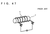
- induction heating has usually used a heating coil c as shown in Fig. 47 in which the material T to be heated is inserted, heated and then pulled out.
- a bonding part j is covered with a gas jacket d as shown in Fig 48 in order to prevent the oxidation of the bonding part j.
- inert gas herein after called shielding gas
- shielding gas inert gas
- the mark c represents a high frequency heating coil.
- the present invention is made to resolve the above-mentioned disadvantages of the prior arts.
- the first aspect of the present invention is a diffusion bonding method which comprises a step of adjusting the ends of materials to be bonded before bonding after they are set in a diffusion bonding apparatus.
- the ends of the materials to be bonded are finished to face parallel to each other as desired at the time of the above-mentioned adjustment.
- the second aspect of the present invention is a diffusion bonding apparatus which comprises a finishing means to finish the ends of the materials so that they face parallel to each other in the diffusion bonding appatatus.
- the diffusion bonding apparatus of the second aspect of the present invention comprises a finishing means comprising a machining means which is symmetrically placed between two materials to be bonded, a first driving mechanism to move said machining means forward and backward for the materials to be bonded and a second driving mechanism to move said first driving mechanism sideways; or a first driving mechanism to move said machining means sideways and a second driving mechanism to move the first driving mechanism forward and backward for the materials to be bonded; a bed; a fixed clamp and a mobile clamp which are placed on the bed facing to each other; and a driving means to move said mobile clamp.
- the first and second aspects of the present invention is comprised in the above way, upon completion of finishing the ends of the materials, the ends of the materials to be bonded can face parallel to each other as desired. Consequently, there will be no need to adjust the ends of the materials in order for them to face parallel to each other when setting the materials in the diffusion bonding apparatus, facilitating an easy and quick setting of the materials in the diffusion bonding apparatus.
- the third aspect of the present invention is a diffusion bonding apparatus comprising a material feeding section and a material discharge section installed in that order, through which material to be bonded are fed from upstream side and bonded materials are discharged toward downstream side wherein said material feeding section has a mechanism to move the material to be bonded to a place where its end is bonded with the other, and to pressurize the bonding part of the materials; and said material discharging section has a mechanism to clamp the material to be bonded.
- a material to be bonded is fed and discharged horizontally or vertically.
- the material feeding section has, for example, a clamping means to clamp the material to be bonded, a transporting and pressurizing means which transports the clamping means to a predetermined place and pressurizes the bonding part; a guiding means to guide the material to be bonded, a feeding and pressurizing means which feeds the material into the place where it is bonded, and pressurizes the bonding part; or a guided feeding and pressurizing means which feeds the material to be bonded into the place where it is bonded with guide and pressurizes the bonding part.
- the guide is carried out while upward movement of the material to be bonded is prevented.
- the fourth aspect of the present invention is a diffusion bonding apparatus comprising a lower mechanism to clamp a material to be bonded vertically, and an upper mechanism positioned upside of the lower mechanism to move a material to be bonded upwards and downwards with clamping.
- the lower mechanism has a base plate positioned horizontally and free open and close clamping means installed on the upper end and the lower end of the base plate respectively; and the upper mechanism has a base plate positioned horizontally at suitable position above the lower mechanism, a pressurizing unit , with a free open and close clamping means, which moves downwards and upwards freely and is located under the base plate of the upper mechanism.
- the pressurizing unit has an adjusting means to adjust the pressurizing power.
- the bonding part is pressurized with the pressurizing means and heated for diffusion bonding. A cycle of these procedures is repeated until an extensively long pipe in a desired length is manufactured.
- the fifth aspect of the present invention is a diffusion bonding apparatus comprising a position adjusting means to adjust a difference in position between two materials to be bonded at their bonding point is detected, and such a difference in position is corrected by adjusting position of the materials to be bonded.
- the sixth aspect of present invention is a diffusion bonding apparatus comprising a position adjusting means to correct a difference in position between the two materials to be bonded at their bonding point by placing an insert between two materials to be bonded.
- the insert for adjustment has a convex fitter in a spherical shape on each end thereof, whereas the materials to be bonded have concave fitters in a spherical shape corresponding to the convex fitters in a spherical shape on the ends to be bonded.
- the seventh aspect of the present invention is a diffusion bonding apparatus with a clamping mechanism which has a sufficient clamping force while causing no deformation to the bonding parts, which otherwise leads to a drop in the strength in the joints.
- the eighth aspect of the present invention is a diffusion bonding apparatus with a clamping mechanism which comprises a first clamping section to clamp the vicinity of the end of the material to be bonded, and a second clamping section to clamp the material at a position further from the end of the material; wherein the first clamping section prevent deformation of the end of the material, while the second clamping section clamps the material firmly so that a predetermined pressure is imposed on the bonding part of the materials. It is preferable that the first clamping section and the second clamping section are located a distance five times longer than the diameter of the material to be bonded.
- the clamping mechanism of the diffusion bonding apparatus of the eighth aspect of the present invention has a clamping section comprises; a first block pawl fixed on a bed or a mobile table in the main body of the diffusion bonding apparatus with its clamping part pointing upward, a second block pawl and a third block pawl which are fixed on the bed or the mobile table in the main body of the diffusion bonding apparatus at their bottoms with fixtures while being allowed to rotate freely, and with their clamping parts facing each other which tops are driven by a driving means installed on the opposite side of their clamping parts; or a first block pawl fixed on the bed or the mobile table of the main body of the diffusion bonding apparatus with its clamping part pointing upward, a second block pawl positioned forming a certain angle with the first block pawl and driven with a driving means which is installed on the bed or the mobile table with fixtures; a third block pawl positioned forming a certain angle with the first block pawl and driven with the driving means installed on the bed or the mobile table with
- the clamping mechanism under the seventh and eighth aspects of the present invention is constructed in either one of the ways mentioned above, it will not create no deformation in the ends of the materials while clamping them. Consequently, the strength in the joint will no longer drop due to a deformation.
- the nineth aspect of the present invention is a diffusion bonding apparatus with a heating coil used for induction heating, being split and joined freely.
- the heating coil under the nineth aspect of the present invention is used for induction heating and comprises a right block and a left block corresponding to the right block; wherein said right block comprising a right heating coil, a right gas jacket covering said right heating coil, and a driving means which moves forward and backward the right heating coil and the right gas jacket for the material to be heated; and said left block comprising a left heating coil, a left gas jacket covering the left heating coil, and a driving means which moves forward and backward the left heating coil and the left gas jacket for the material to be heated. It is preferable that the gas jacket feeds more gas from the upper side thereof in the heating coil under the nineth aspect of the present invention.
- the heating coil comprises, for instance, a circular coil and connecting components which are incorporated into both ends of the coil.
- the connecting components of the light block and the connecting components of the left block are clamped to each other, and that the heating coil is water cooled.
- the tenth aspect of the present invention is a diffusion bonding apparatus with an induction heating device having the above-mentioned heating coil.
- the eleventh aspect of the present invention is an induction heating method wherein induction heating is carried out while the distance between the lower outside of a material to be heated and the lower inside of the heating coil is kept shorter than the distance between the upper outside of the material to be heated and the upper inside of heating coil.
- the twelfth aspect of the present invention is an induction heating method wherein induction heating is carried out while the upper outside of a material to be heated is more cooled than other part of the material to be heated by feeding more gas from the upper side of the gas jacket.
- the construction of the heating coil as mentioned above allows for the following procedure: to split the heating coil, set a long material such as a pipe in a specified place, join the heating coil, treat the material with heat by induction heating, re-split the heating coil, and remove and transfer the heated material to the place where it receives the next processing step.
- a long material such as a pipe
- join the heating coil treat the material with heat by induction heating
- re-split the heating coil and remove and transfer the heated material to the place where it receives the next processing step.
- the thirteenth aspect of the present invention is a diffusion bonding apparatus with a shielding device for a bonding part in diffusion bonding comprising a main gas jacket with a high frequency heating coil, and a front gas jacket and a back gas jacket incorporated in the feeding side and the discharging side of the main jacket respectively.
- the front gas jacket and back gas jacket comprises several blocks where shielding gas is supplied; that the main gas jacket, front gas jacket and back gas jacket are divided into two parts respectively and each part freely moves forward and moves backward for the materials to be bonded.
- the fourteenth aspect of the present invention is a shielding method for a bonding part in diffusion bonding employing a shielding device which comprises a main gas jacket with a high frequency heating coil, and a front gas jacket and a back gas jacket incorporated in the feeding side and the discharging side of the main gas jacket respectively wherein the internal pressure of main gas jacket is kept lower than the internal pressure of the front and back gas jackets at the time of shielding.
- the front gas jacket and/or the back gas jacket are comprises several blocks where the shielding gas is fed, and internal pressure of the block located closer to the main gas jacket is lower than those of the rest of blocks.
- the shielding is carried out as follows:
- the shielding gas is supplied to the main gas jacket, the front gas jacket and the back gas jacket respectively.
- the shielding gas fed into each gas jacket leaks out of the gap created between the gas jackets and the materials. Since the shielding gas fed into the main gas jacket needs to go through the gaps created in the front and back gas jackets respectively before it goes out, it moves much slower than it does in the conventional gas jackets. In other words, the shielding gas fed into the main gas jacket stays there much longer than it does in the conventional gas jackets. Also, this prolonged stay in the main jacket allows the shielding gas in the main jacket to be heated with the heat generated during diffusion bonding. With these effects, the circumference of the bonding part is not cooled, and the degeneration in quality and strength in the joints is avoided. It means that the improvement of quality and strength of the joints is achieved.
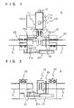
- Fig. 1 and Fig. 2 show Embodiment 1 of a diffusion bonding apparatus A employing the diffusion bonding method of the present invention.
- This diffusion bonding apparatus A of Embodiment 1 mainly consists of: a finishing means 10 to finish the ends of materials to be bonded, a bed 21, a fixed clamp 22 mounted on the bed 21, a mobile clamp 23 mounted on the bed 21 facing the fixed clamp 22, driving means 24 to move the mobile clamp 23, and an induction heating means 25 which is mobile and heats the ends of materials to be bonded.
- the finishing means 10 comprises a machining component 11 to finish the ends of the materials, an electric motor (a first drive mechanism) 12 to move the machining component 11 forward and backward for the materials to be bonded, and a sideways slidable table (a second drive mechanism) 13 to move the electric motor 12 along a horizontal axis of the bed 21.
- a machining component 11 to finish the ends of the materials
- an electric motor (a first drive mechanism) 12 to move the machining component 11 forward and backward for the materials to be bonded
- a sideways slidable table (a second drive mechanism) 13 to move the electric motor 12 along a horizontal axis of the bed 21.
- the machining component 11 concretely, comprises a main body 11a of the machining component 11 which is driven by the electric motor 12; a rotating head 11c which is rotated through a power transmission mechanism (not shown) of a motor 11b installed in the main body 11a of the machining component 11; a fixed side finishing means 11e, attached to the rotating head 11c through a supporter 11d, finishing the end of a tube T1 set in the fixed clamp 22, and a mobile side finishing means 11f, which is also attached to the rotating head 11c through the supporter 11d finishing the end of a tube T2 set in the mobile clamp 23.
- the fixed side finishing means 11e and the mobile side finishing means 11f are positioned symmetrically to the vertical axis of the rotating head 11c.
- finishing means, both 11e and 11f are, for example, rotating elements with edges, and both edges of the finishing means 11e and 11f are in an aligned position so that the end of the material to be finished with the finishing means 11e and the end of the material to be finished with the finishing means 11f face parallel to each other.
- edges grindstones can be used.
- the mobile clamp 23 moves forward and backward for the fixed clamp 22 being guided by guide-rails 21a and 21a which are laid along the horizontal axis of the bed 21.
- the mobile clamp driving means 24 can be a hydraulic cylinder, for example, and is installed on one side as shown in Fig. 1. However, it can be installed on both sides of the mobile clamp 23.
- the bonding work under this Embodiment 1 only requires to insert the tube T into the clamps 22 and 23, thus allowing a substantially easier and quicker setting of the tube T in the diffusion bonding apparatus A.
- Fig. 11 and Fig. 12 show a diffusion bonding apparatus A1 pertinent to Embodiment 2 under the present invention.
- the diffusion bonding apparatus A1 of Embodiment 2 mainly consists of a bed B10, a fixed clamp B21 fixed on the one side (the discharging side) B10b of the bed B10, and a mobile clamp B31 fixed on the other side (the feeding side) B10a of the bed B10 which faces the fixed clamp B21 and moves backward and forward.
- a material feeding section B30 is constructed
- this fixed clamp B21 as a center
- a material discharging section B20 is constructed.
- the fixed clamp B21 concretely comprises a main clamping body B22 fixed on the upper side B10c of the bed B10, a clamping section B25 comprising a fixed block pawl B23 and a mobile block pawl B24 which clamps the material P1 in a joint action with the fixed block pawl B23, and pawl driving hydraulic cylinders B26 and B26, horizontally mounted on a fixture B22a of the main clamping body B22 in two rows, to drive the mobile block pawl B24; and the fore-end B27a of piston-rod B27 of the pawl driving hydraulic cylinder B26 is connected to the back of the mobile block pawl B24.
- the mobile block pawl B24 moves forward and backward for the fixed block pawl B23.
- the mobile clamp B31 concretely comprises a main clamping body B32 which runs on a pair of rails B11 and B11 installed on the upper side BlOc of the bed B10 in the direction of the mobile clamp B21, main body driving hydraulic cylinders B38 and B38 which are mounted on the fore-end of the bed B10 (the end where the material is fed from) and which move the main clamping body B32 on the pair of rails B11 and B11 and pressurize the material P2 at a predetermined pressure, a clamping section B35 comprising a fixed block pawl B33 fixed on the main clamping body B32 and a mobile block pawl B34 which clamps the material P2 in a joint action with the mobile block pawl B34, and pawl driving hydraulic cylinders B36 and B36, horizontally mounted on a fixture 32a of the main body B32 in two rows, to drive the mobile block pawl B34; and the top B39a of a piston-rod B39 of the main body driving hydraulic cylinder B38
- the main clamping body B32 runs on the rails B11 and B11 forward and backward for the fixed clamp B21. Also, along with the movement of the piston-rod B37 of the pawl driving hydraulic cylinder B36, the mobile block pawl B34 moves forward and moves backward for the fixed block pawl B33.
- Numeral B40 in Fig. 11 represents a finishing device to finish the ends of the materials P1 and P2.
- the shape of the mobile block pawls B23 and B33 and the fixed block pawls B24 and B34 can be one of those shown in Fig. 13 with the mark (a), (b), or (c).
- a pipe of any desired length can be manufactured by diffusion bonding.
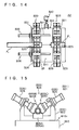
- FIG. 14 and Fig. 15 show a diffusion bonding apparatus A2 pertinent to Embodiment 3 under the present invention.
- This Embodiment 3 is a modification of Embodiment 2 having a clamping section B25 (B35) comprising the first block pawl B25A (B35A), the second block pawl B25B (B35B), and the third block pawl B25C (B35C).
- the first block pawl B25A (B35A) is fixed on the bottom of the main clamping body B22 (B32), while the second block pawl B25B (B35B) and the third block pawl B25C (B35C) are driven with a pawl driving hydraulic cylinder B26 (B36).
- the second block pawl B25B (B35B) with its pawl driving hydraulic cylinder B26 (B36) and the third block pawl B25C (B35C) with its pawl driving hydraulic cylinder B26 (B36) form an angle of 120 or 90 degrees. (refer to Fig. 15)
- Embodiment 3 is the same as those of Embodiment 2.
- Embodiment 3 of the above construction and operation a pipe or other product of a specified length is manufactured by diffusion bonding in the same way as Embodiment 2.
- the clamping section B25 (B35) comprising the first, the second, and the third block pawls B25A (B35A), B25B (B35B), and B25C (B35C) respectively, and to the pawl driving hydraulic cylinders B26, B26 (B36, B36) mounted on the pawls in a slant direction, although materials P1 (P2) can be clamped uniformly in the diffusion bonding apparatus A2, the width of Embodiment 3 is smaller than that of Embodiment 2. The effect is not obtained by Embodiment 2.
- Fig. 16 shows the major section of a diffusion bonding apparatus A3 pertinent to Embodiment 4 under the present invention.
- This Embodiment 4 is a modification of Embodiment 2 having a clamp comprising a main clamping body B22 (B32) and a clamping section B25 (B35) comprising a right block pawl B24A (B34A) and a left block pawl B24B (B34B) which freely slide on the main clamping body B22 (B32).
- the material P1 (P2) is clamped by opening and closing the right block pawl B24A (B34A) and the left block pawl B24B (B34B) with the pawl driving hydraulic cylinders B26, B26 (B36, B36) which face to each other with the right block pawl B24A (B34A) and the left block pawl B24B (B34B) between them.
- the top of the piston-rod B39a of mobile clamp driving hydraulic cylinder is connected to a connector B321 installed on the back of the front part of the main clamping body B32.
- Fig. 16 shows that the apparatus has one mobile clamp driving hydraulic cylinder B38, it can have two hydraulic cylinders as is described in Embodiment 2.
- Embodiment 4 is the same as those of Embodiment 2.
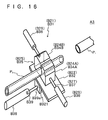
- Fig. 17 shows the main section of a diffusion bonding apparatus A4 pertinent to Embodiment 5 under the present invention.
- This Embodiment 5 is a modification of Embodiment 2 employing a mechanism B25D (B35D) similar to the mechanism employed for the chuck of lathe in its clamping section B25 (B35).
- Embodiment 5 is the same as those of Embodiment 4. Its operation is also the same as that of Embodiment 4 except for the operation of the clamping section B25 (B35).
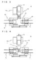
- Fig. 8 shows the main section of a diffusion bonding apparatus A5 pertinent to Embodiment 6 under the present invention.
- This Embodiment 6 is a modification of Embodiment 2 having a guiding means B50 to guide the material P2 instead of the mobile clamp B31 and a feeding and pressurizing means B60 which feeds and pressurizes the material P2.
- the guiding means B50 comprises a pair of the guiding mechanisms B51 and B51 of the identical construction installed side by side.
- This guiding mechanism B51 comprises a main guiding body B52, and the guiding section B53 having a right guiding component B53A and a left guiding component B53B both of which slide freely on the main guiding body B52.
- the feeding and pressurizing means B60 is concretely a hydraulic cylinder (for feeding and pressurizing) B61 having a feeding and pressurizing component B63 in a disc shape mounted on the fore-end of the piston-rod B62.
- a hydraulic cylinder (for feeding and pressurizing) B61 having a feeding and pressurizing component B63 in a disc shape mounted on the fore-end of the piston-rod B62.
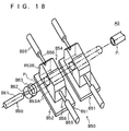
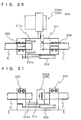
- Fig. 19 shows the main section of a diffusion bonding apparatus A6 pertinent to Embodiment 7 under the present invention.
- This Embodiment 7 is a modification of Embodiment 2 having a guiding-and-feeding / pressurizing means B70 for the material P2 instead of the mobile clamp B31 and a preventing means B76 to prevent the material P2 from moving upward.
- the guiding-and-feeding pressurizing means B70 concretely comprising a driving roller B71 and a driven roller B72 set positioned in a specified interval and tied up with a feeding pressurizing belt B73 carrying specified friction and another set of the same, both of which are installed to face each other. These two feed the material P2 while holding it, and then pressurize it.
- the preventing means B76 to prevent the material from moving upward concretely comprises two rollers B77 and B77 which are positioned on the fore-side and back-side of the guiding-and-feeding pressurizing means B70 respectively, and contact the surface of the material P2.
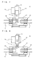
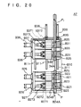
- Fig. 20 and Fig. 21 show a diffusion bonding apparatus A7 pertinent to Embodiment 8 under the present invention.
- This Embodiment 8 is a modification of Embodiment 2 having a pair of fixed clamps B21 and a pair of mobile clamps B31, which are driven with the hydraulic cylinders B26, B26, B26 and B26.
- the clamp B21 (B31) comprises a main clamping body B22 (B32); a clamping section B25 (B35) comprising a fixed wide block pawl B23 (B33) fixed on the main clamping body B22 (B32), a front-part mobile block pawl B24A (B34A) to clamp the material P1 (P2) together with the front-part of the fixed wide block pawl B23 (B33), and a rear-part mobile block pawl B24B (B34B) to clamp the material P1 (P2) together with the rear-part of the fixed wide block pawl B23 (B33); a front-part driving rod B271 (B371) connected to the back of the front-part mobile block pawl B24A (B34A); a rear-part driving rod B272 (B372) connected to the rear-part mobile block pawl B24B (B34B); a connecting component B273 (B373) which connects the back-end of the front-part driving rod
- Embodiment 8 is the same as those of Embodiment 2.
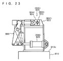
- FIG. 22 and Fig. 23 show a diffusion bonding apparatus A8 pertinent to Embodiment 9 under the present invention.
- This Embodiment 9 is a modification of Embodiment 2 having a construction wherein the pawl driving hydraulic cylinder B26 (B36) for the mobile block pawl B24 (B34) is installed in the lower part of the clamping section B25 (B35) of the box- shaped main clamping body B22 (B32), and the mobile block pawl B24 (B34) is driven through the linking mechanism B80.
- Embodiment 9 is the same as those of Embodiment 2.
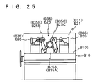
- Fig. 24 and Fig. 25 show a diffusion bonding apparatus A9 pertinent to Embodiment 10 under the present invention.
- This Embodiment 10 is a modification of Embodiment 3 having a construction wherein the second and the third block pawls (mobile block pawl) B25B, B25C (B35B, B35C) mounted on the main clamping body B22 (B32) revolt freely by being driven with the pawl driving hydraulic cylinders B26 and B26 (B36 and B36) which are installed to face these second and third block pawls B25B, B25C (B35B, B35C).
- Embodiment 10 is the same as those of Embodiment 3.
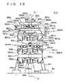
- Fig. 26 shows a diffusion bonding apparatus A10 pertinent to Embodiment 11 under the present invention.
- This diffusion bonding apparatus A10 of Embodiment 11 mainly consists of a lower mechanism B90A installed on a base BA which supports the material P1 on the lower side in a vertical direction; an upper mechanism B90B which is located above the lower mechanism B90A while being sustained by a means of sustaining the material P2 on the upper side which presses it on to the material P1 on the down side with a predetermined pressure; a finishing device B42 to finish the ends of the materials P1 and P2; and a heating device B44 to bond the materials P1 and P2 by diffusion bonding.
- the lower mechanism B90A comprises a plate B92 which is horizontally supported by legs B91 on the base BA, and has a hole (not clearly indicated in the drawing) in which the material P1 on the lower side goes through; and an upper side clamping means B93A and a lower side clamping means B93B which are both installed on the upper end B92a and the lower end B92b of the plate B92 respectively.
- Both the upper side clamping means B93A and the upper side clamping means B93B have a pair of mobile clamps B94 positioned to face to each other.
- the mobile clamp B94 comprises a clamping section B94b which has a mobile block pawl B94a to run on a pair of rails B95 and B95 located on the upper end of the plate B92a and the lower end of the plate B92b respectively; and a main body driving hydraulic cylinder B94c which moves the clamping section B94b on the rails B95 and B95.
- the main body driving hydraulic cylinder B94c is fixed on a block B92c located on the plate B92.
- the upper mechanism B90B comprises a plate B96 supported in an appropriate manner and located above the lower mechanism B90A; a pressurizing unit B97 installed beneath the plate B96; a lifting means B98 to lift up and down the pressurizing unit B97; pressure adjusting means B99 to adjust the pressure applied on the bonding part; and a clamping means B93C installed in the pressurizing unit B97.
- the clamping means B93C is concretely a mobile clamp B94, and its main body driving hydraulic cylinder B94c is fixed on fixture of the pressurizing unit B97.
- the pressurizing unit B97 comprises a pressurizing section B97a and a pressure adjusting section B97b which adjusts the pressure of the pressurizing section B97a.
- the pressurizing section B97a comprises a lower block B97c in a shape of gantry; a middle block B97e shaped in a trapezoid and connected directly with the upper end B97d of the lower block B97c; and an upper block B97g directly connected with the upper end B97f of the middle block B97e.
- an adjusting block B97i which is a component of the pressure adjusting section B97b, is located with a pressure adjusting part B97j facing the upper end B97d of an adjusting block of the lower block B97c.
- the lifting means B98 concretely comprises a pair of hydraulic cylinders B98a and B98a facing each other around the central axis of the upper mechanism B90B, and a pair of guiding axes B98b and B98b which guide the movement of the pressurizing unit B97 driven by the hydraulic cylinder B98a and are positioned outside the hydraulic cylinders B98a and B98a respectively.
- a bonding component B94d located on the end of a piston-rod B98c of the hydraulic cylinder B98a joins with the upper end of the upper block B97g of the pressurizing unit B97.
- the end of the guiding axis B98b can freely slide in a cylindric cavity (illustration omitted) which is located around the upper block B97g and the middle blocks B97e.
- the pressure adjusting means B99 adjust the pressure of adjusting section B97b to be applied to the upper end B97d of the lower block B97c, thereby adjusts the pressure to be applied to the bonding part.
- the pressure adjusting means B99 comprises a lifting screw component B99a connected with the adjusting block B97i, thereby lifts the adjusting block B97i up and down; a female screw block B99b which the lifting screw component B99a is screwed into, and which is positioned on the upper end of the upper block B97g; a bevel gear B99c positioned on the upper end of the screw component for lifting B99a; another bevel gear B99d which gears the bevel gear B99c; a rotating axis B99e with its end connected to the bevel gear B99d; a rotation handle B99f which is connected to the rear end of the rotating axis B99e; a support pipe B99g which supports the rotating axis B99e; and a lock screw B99h attached to the support pipe B99g
- the finishing device B42 grinds the ends of the materials P2 of upstream side and the material P1 of downstream side. It comprises a pair of grinding components B42a and B42a which is located with facing the bonding surface of the materials P1 and P2 respectively; a motor B42b which rotates the grinding components B42a and B42a; a transporting mechanism (illustration omitted) which transports the motor B42b along the bonding surface.
- the heating device B44 heats the bonding part while sealing it with sealing gas. It comprises split heating coils B44A and B44A which have gas jackets. The split heating coils B44A and B44A move freely in the direction of the bonding part, and at the bonding part these two come together to heat the bonding part.
- the desired length of a pipe can be manufactured by diffusion bonding.
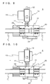
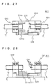
- Fig. 27 to Fig. 29 illustrate a position adjusting means to adjust position of materials under a diffusion bonding apparatus A11 of Embodiment 12 of the present invention.
- This position adjusting means mainly consists of a bed C11, a first clamp C21 placed on the bed C11, a second clamp C22 placed on the bed C11 facing the first clamp C21, a driving means C23 to drive the second clamp C22, a detection means C30 to detect a difference in position at the bonding point C30, and a control device C40.
- the first clamp C21 has a built-in fine adjustment means C21a that moves up and down or right and left and corrects a difference in position between two materials to be bonded at their bonding point.
- the second clamp C22 moves forward and backward for the first clamp C21 running on a pair of guide-rails C11a and C11a which are laid along the horizontal axis of the bed 11.
- the driving means C23 to drive the second clamp C22 is a hydraulic cylinder, for example, and it can be installed on both sides of the second clamp C22 although it is installed on one side in Fig. 27.
- the detection means C30 to detect a difference in position comprises a pair of position detection sensors C31 and C31 with each placed in the horizontal direction and in the vertical direction on the side of the first clamp C21 to detect a horizontal and vertical position of the bonding point of the material clamped with the first clamp C21; a pair of position detection sensors C31 and C31 with each placed in the horizontal direction and in the vertical direction on the side of the second clamp C22 to detect a horizontal and vertical position of the bonding point of the material clamped with the second clamp C22, and an amplifier C32 to amplify signals sent from these sensors C31, C31, 31 and C31 respectively (refer to Fig.
- the control device C40 is equipped with, for example, a ROM and a RAM with a CPU as a center.
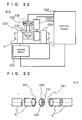
- Fig. 30 to Fig. 32 illustrate another position adjusting means to adjust position of materials under a diffusion bonding apparatus A12 of Embodiment 13 of the present invention
- this position adjusting means mainly consists of a bed C11; a first clamp C24 firmly placed on the bed C11; a second clamp C22 placed on the bed C11 facing the first clamp C24; a driving means C23 to drive the second clamp C22; correcting means C25 to correct a difference in position; a detecting means C30 to detect a difference in position at the bonding point; and a control device C40.
- the correcting means C25 correct a difference in position is concretely a multiple-joint robot C25A having hands to hold the end-parts of the materials T1 and T2.
- the location of the robot C25A is adjusted so that it can hold somewhere in the vicinity of the bonding point of the two materials while avoiding interfering with the position detection sensors C31, C31, C31, and C31.
- the position detection sensors C31, C31, C31, and C31 are omitted in Fig. 30 to Fig. 32.
- the second clamp C22 and others of the position adjusting means in Embodiment 13 is constructed in the same way as those of Embodiment 12.
- Embodiment 13 a difference in position between the materials T1 and T2 is corrected in the above-mentioned way.
- Fig. 33 illustrates another position adjusting means to adjust position of materials under a diffusion bonding apparatus A13 of Embodiment 14 of the present invention.
- This position adjusting means is to correct a difference in position between the materials T1 and T2 with an insertion of an aligning component 50 between the two.
- the position adjusting means used in Embodiment 14 is the same as that in Embodiment 13 except for a correcting means 25 which Embodiment 14 does not requires.
- the procedures of correcting a difference in position under this Embodiment 14 are: to form concave fitters in a spherical shape C61 and C61 on each of the bonding ends of material T1 and T2; to form convex fitters in a spherical shape C51 and C51 which fit the concave fitters in a spherical shape C61 and C61 respectively on both ends of an insert (aligning component) C50 which has the same outer diameter and inner diameter of those of materials T1 and T2; to fix the insert C50 over the bed C11 in an appropriate manner while fitting one of convex fitters C51 in the concave fitter C61 on the material T1 clamped with the first clamp C24; to drive the driving means C23 to move the second clamp C22 towards the first clamp C24; to fit the concave fitter C61 on the material T2 clamped with the second clamp C22 in the convex fitter C51 on the other side of the insert C50; and to move the insert (align
- the convex fitters C51 and C51 and concave fitters C61 and C61 are all in a spherical shape, the convex fitters C51 and C51 on the bonding ends of the materials T1 and T2 smoothly slide in.
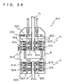
- Figs. 34 and 35 show a diffusion bonding apparatus A14 with a clamping mechanism pertinent to Embodiment 15 under the present invention.
- This clamping mechanism C is installed on both the material discharging side and feeding side.
- Each of the clamping mechanisms C1 and C2 comprising a first clamping part D10 which clamps the vicinity of the end of the material P; and a second clamping part D20 which is located further from the end of the material P and clamps the material P in that position. While the first clamping part D10 carries the clamping force necessary to correct a deformation created in the end of the material P, the second clamping part D20 carries the clamping force necessary to apply a predetermined pressure to the bonding part of the material P.
- this clamping mechanism C have a clamping means, i.e. the first clamping part D10 and the second clamping part D20, which do not create a deformation in the end of the material P, which otherwise causes a drop in the strength in a joint.
- the material P is concretely a pipe.
- the first clamping part D10 of the clamping mechanism on the material discharging side (the discharge clamping mechanism) C1 which clamps the pipe P1 on the discharging side concretely comprises a first block pawl having a holding part D11a in the shape of a circle; a second block pawl D12 having a holding part D12a in the shape of a circle; and a third block pawl D13 having a holding part D13a in the shape of a circle.
- the first block pawl D11 is fixed on a bed B of the main body of the diffusion bonding apparatus A14 with its holding part D11a pointing upward; and the second block pawl D12 and the third block pawl D13 are fixed on the bed B at their bottoms with fixtures D2 and D3 respectively while being allowed to freely rotate, with their holding parts D12a and D13a facing each other, and with their tops connected to a piston-rod D14a and a piston-rod D15a of a pawl driving hydraulic cylinder D14 and a pawl driving hydraulic cylinder D15 respectively.
- both pawl driving hydraulic cylinders D14 and D15 is adjusted to give the second block pawl D12 and the third block pawl D13 the clamping force needed to correct a deformation created in the ends of the pipes P1 and P2 respectively.
- the second clamping part D20 comprises a first block pawl D21 having a holding part D21a; a second block pawl D22 having a holding part D22a; and a third block pawl D23 having a holding part D23a.
- the first block pawl D21 is fixed on a bed B of the main body of the diffusion bonding apparatus A14 with its holding part D21a pointing upward; and the second block pawl D22 and the third block pawl D23 are fixed on the bed B at their bottoms with fixtures D2 and D3 respectively while being allowed to freely rotate, with their holding parts D22a and D23a facing each other, and with their tops connected to a piston-rod D24a and a piston-rod D25a of a pawl driving hydraulic cylinder D24 and D25 for located outside thereof respectively.
- the driving power of both pawl driving hydraulic cylinders D24 and D25 for the block pawls is adjusted to give the second block pawl D22 and the third block pawl D23 the needed clamping force to apply a predetermined pressure to the bonding part of the pipes P1 and P2.
- all the components of the second clamping part D20 are indicated with marks in brackets in Fig 35.
- the clamping mechanism (the feeding side clamping mechanism) C2 on the feeding side to hold the pipe P2 on the feeding side has the same construction as the above clamping mechanism C1 on the discharging side, except that the first block pawls D11 and D21, the second block pawls D12 and D22, and the third block pawls D13 and D23 are all fixed on a mobile table S which is installed on the bed B of the main body.
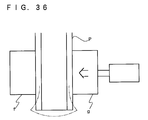
- the clamping mechanism C comprises the first clamping part D10 and the second clamping part D20; and the first clamping part D10 carries the needed clamping force to correct any deformation created in the end of the pipe , while the second clamping part D20 carries the needed clamping force to apply the predetermined pressure to the bonding part of the pipe P. Consequently, clamping the end of the pipe P with the clamping mechanism C of the above construction does not create a deformation in the end of the pipe P as shown in Fig. 36. Therefore, the strength in the joint will not drop any longer due to deformation created in the end of the pipe P.
- mark f and g indicate block pawls for clamping.
- Fig. 37 shows a side view of a clamping part of a clamping mechanism C pertinent to a diffusion bonding apparatus A15 of Embodiment 16 under the present invention.
- This Embodiment 16 is a modification of Embodiment 15, wherein the second block pawls D12 and D22 and the third block pawls D13 and D23 of the first clamping part D10 and the second clamping part D20 respectively move freely with their backs connected to the ends of the piston-rods D14a, D24a, D15a, and D25a of the pawl driving hydraulic cylinders D14, D24, D15, and D25 respectively which are all mounted on the bed B with the fixtures D4 downward and diagonally at a specified angle.
- the construction except for the above), the function, and the effect of Embodiment 16 are all the same as those of Embodiment 15.
- all the components of the second clamping part D20 are indicated with marks in brackets in Fig 37.
- Fig. 38 shows a clamping mechanism C pertinent to a diffusion bonding apparatus A16 of Embodiment 17 under the present invention.
- This Embodiment 17 is employed in a diffusion bonding apparatus in which the pipe P is fed vertically, whereas Embodiment 15 and Embodiment 16 are employed in a diffusion bonding apparatus in which the pipe P is fed horizontally.
- Embodiment 17 the first block pawls D11 and D21 of the first clamping part D10 and the second clamping part D2 move freely while being driven by the pawl driving hydraulic cylinders D17 and D27; and the pawl driving hydraulic cylinders D17, D27, D14, D24, D15 and D25 which drive the block pawls D11, D21, D12, D22, D13, and D23 respectively are all supported by supporters D5 installed in the diffusion bonding apparatus.
- the construction except for the above, the function, and the effect of Embodiment 17 are all the same as those of Embodiment 15. To make the drawing simple, all the component of the second clamping part D20 are indicated with marks in brackets in Fig 38.
- Embodiment 15 to Embodiment 17 it is preferred to locate the first clamping part D10 and the second clamping part D20 a distance five times longer than the diameter of the material P in order to avoid a creation of a deformation in the bonding part by the second clamping part D20.
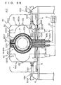
- Fig. 39 and Fig. 40 show a heating coil under a diffusion bonding apparatus A17 of Embodiment 18 under the present invention.
- This heating coil El comprises a right block E2 and a left block E3 so that it can be split into two blocks, and is mounted on the bed B.
- the right block E2 comprises a right heating coil E21, a right gas jacket E22 which covers the right heating coil E21, and a driving means E23 which moves the right heating coil E21 and the right gas jacket E22 in the horizontal direction (moving forward and moving backward for the material P); while the left block E3 comprises a left heating coil E31, a left gas jacket E32 which covers the left heating coil E31, and a driving means E33 which moves the left heating coil E31 and the left gas jacket E32 in the horizontal direction (moving forward and moving backward for the material P).
- the right heating coil E21 comprises a semicircle coil E24 and two connecting components incorporated in each side of the coil E24, i.e. the upper connecting component E25 and the lower connecting component E26.
- this coil E24 is constructed, for example, by two square bronze pipes E4 positioned side by side connection, and the cooling water runs inside the pipes for the prevention of burn-out of the coil E24.
- one square pipe E4A constitutes the one way E51 of the cooling water channel E5
- the other square pipe E4B constitutes the other way E52 of the cooling water channel E5.
- the upper connecting component E25 in a block having a turning channel E53 at its bottom where the cooling water channel E5 makes a turn from the one way E51 to the other way E52, and a hole E251 for a bolt E6 for clamping in its upper part.
- the upper connecting component E25 is incorporated into the upper side of the coil E24.
- the lower connecting component E26 is a block having a cooling water supply channel E54 connected to the one way E51 and a cooling water discharge channel E55 connected to the other way E52 in its upper side, a hole E261 for a bolt E6 for clamping in its center, and the connecting part E262 to the power source in its bottom.
- This lower connecting component is incorporated into the bottom of the coil E24.
- a power source cable E7 is connected to the connecting component E26 with flexibility.
- the coil E24 is not only limited in such a form as shown in Fig. 41 (a), but it can be a bronze component E8 having two cooling water pipes E5a and E5b on each side as shown in Fig. 41 (b).
- the right gas jacket E22 is box-shaped. Its left side E221 has an opening leading to the right heating coil E21, and both the left end of its front E222 and the left end of its back E223 have a semicircular cutout to fit the pipe P to be heated. Its right side E224 has a gas nozzle E9 to feed shield gas, while its bottom has a cutout piercing into the lower connecting component (no clear indication is given in the drawing). As shown in Fig. 39, the right side E224 has a connecting pipe E56 to be connected to the cooling water supply channel E54 and a connecting pipe E57 to be connected to the cooling water discharge channel E55.
- sliding components E226 and E226 are installed in a certain interval which slide on the guide rails R and R mounted on the bed B.
- the right gas jacket E22 of the above construction is connected to the right heating coil E21 in the appropriate way.
- the top E227 of the right gas jacket E22 is not specifically indicated in the drawing, however, it is freely opened and closed so that it can be clamped by piercing the bolt E6 through the hole E251 in the upper connection component E25.
- connection between the connecting pipe E56 and the cooling water supply pipe (not shown) , the connection between the connecting pipe E57 and the cooling water discharge pipe (not shown) , and the connection between the gas nozzle E9 and the shield gas pipe (not shown) are all made with flexible tubes, although these are not illustrated in the drawings.
- the right block driving means E23 concretely comprises a hydraulic cylinder E23A hooked on the right side E224 of the right gas jacket E22 and a pair of guide-rails R and R on which the right gas jacket 22 runs.
- the hydraulic cylinder E23A and the guide-rails R and R are installed on the bed B in the direction of the pipe P to be heated.
- the right block driving means E23 of the above construction when the piston-rod E231 moves forward and moves backward, the sliding component E226 slides on the guide-rail R and the right gas jacket E22 also moves forward and moves backward for the pipe P.
- the left heating coil E31, the left gas jacket E32, and the left block driving means E33 are all constructed in the same way as the right heating coil E21, the right gas jacket E22, and the right block driving means E23 respectively, except that they are positioned symmetrically with those of the right side.
- the material P such as a long pipe can be very quickly placed in and displaced out of the heating coil El, since the heating coil El is split into the right heating coil E21 and the left heating coil E31, and both of them are free to open and close to allow the pipe P to go through. With this, the work efficiency of induction heating of the material P, such as a long pipe, remarkably improves.
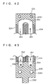
- Fig. 44 shows a heating coil under a diffusion bonding apparatus A18 of Embodiment 19 pertinent to the present invention.
- This Embodiment 19 is a modification of Embodiment 18. It has gas nozzles E9 and E9 on the tops of the right gas jacket E22 and the left gas jacket E32 respectively.
- the construction of the heating coil El under Embodiment 19 of the present invention is the same of that of Embodiment 18 except for the above.
- the right gas jacket E22 and the left gas jacket E32 have the gas nozzles E9 and E9 respectively on their tops. Because of the cooling effect produced by the shield gas ejecting through the gas nozzles E9 and E9, the upper part of the pipe P is prevented from being excessively heated. Thus, the pipe P is uniformly heated.
- Embodiment 18 and Embodiment 19 the materials to be heated are fed in a horizontal direction. However, a vertical feeding is also possible. In that case, because the heated shielding gas stays in the upper part of the gas jacket, it is desirable to have the gas nozzles on the top of the gas jacket for the uniform heating of the material. Also, according to the above Embodiment 18 and Embodiment 19, the split coils are clamped with bolts and nuts. However, the means of clamping is not only limited to bolts and nuts, but also other means of adequate construction. It is not necessary to clamp the split coils with, for example, bolts and nuts, if the desirable electric current is secured.
- Fig. 45 shows the section of the shielding device F1 under diffusion bonding apparatus A19 of Embodiment 20 pertinent to the present invention.
- This shielding device F1 is used in diffusion bonding where the material P is fed and discharged vertically. It comprises a main gas jacket F10 with a high frequency heating coil FC and shielding gas inlets F11; an upper gas jacket (a front gas jacket) F20 with shielding gas inlets F21, which is incorporated in the upper side (the front) of the main gas jacket F10; and a lower gas jacket (a back gas jacket) F30 with the shielding gas inlets F31, which is incorporated in the lower side (back) of the main gas jacket F10.
- the shielding gas inlets F11 are located to face to each other for the main gas jacket F10, while the shielding gas inlets F21 and F31 are also located to face to each other for the upper gas jacket and the lower gas jacket.
- the upper gas jacket F20 and the lower gas jacket F30 comprises several blocks FB which have for the shielding gas inlets F21 and F31 respectively.
- there are two blocks FB located on the top and the bottom of the main gas jacket i.e., the first block FB1 is located closer to the main gas jacket F10 and the second block FB2 is located further from the main gas jacket F10.
- the first block FB1 is located closer to the main gas jacket F10
- the second block FB2 is located further from the main gas jacket F10.
- the gaps between the main gas jacket F10 and the material P; the upper gas jacket F20 and the material P; and the lower gas jacket F30 and the material P are as large as those created in the conventional devices.
- the shielding of the bonding part J in diffusion bonding under the above shielding device F1 is achieved by supplying the shielding gas in the main gas jacket F10, the upper gas jacket F20 and the lower gas jacket F30 through the shielding gas inlets F11, F21 and F31 respectively.
- the shielding gas fed into the gas jackets F10, F20 and F30 respectively runs through the gaps created between the material and each of the gas jackets F10, F20 and F30 respectively, and leaks out.
- the shielding gas fed into the main gas jacket F10 needs to run through the gap created between the material and the upper gas jacket F20 and the lower gas jacket F30 respectively until it leaks outside.
- the upper gas jacket F20 and the lower gas jacket F30 comprise the blocks FB1 and FB2.
- the shielding gas fed into the main gas jacket F10 stays longer in the gas jacket.
- the prolonged presence of the shielding gas in the main gas jacket F10 helps heat the shielding gas from the heat generated during diffusion bonding. Consequently, although the shielding gas eventually leaks out, the above effects help avoid the degeneration in quality and a loss of strength of the bonding part J. In other words, the quality and the strength of the bonding part J is improved.
- the materials are fed and discharged vertically.
- horizontal feeding and discharging is also possible.
- the main gas jacket and the front and back gas jackets located in the front and back of the main gas jacket are divided into two respectively, it is preferable that each division moves forward and moves backward freely for the material.
- the materials to be bonded are pipes or tubes.
- the materials to be bonded are pipes or tubes.
- it is not only limited to pipes or tubes, but it can also be rails, for example.
- the clamps are fixed and mobile, however, they can both be mobile.
- the present invention gives diffusion bonding such an excellent effect that the ends of the materials can face parallel to each other at the time when the finishing of the ends is completed, requiring no adjustment of the ends of the materials to make them face parallel to each other at the time of the setting of the materials in the diffusion bonding apparatus and facilitating an easy and quick setting of the materials in the diffusion bonding apparatus.
- the present invention achieves such an excellent effect that materials to be bonded contact each other without a difference in position between the two. Consequently, bonding the two materials under the above condition by diffusion bonding will cause no difference in the joint which may be otherwise caused by a difference in position, thus effectively avoiding a loss of strength owing to a difference in the joint.
- the clamping section of the diffusion bonding apparatus under the present invention comprises the means of clamping that does not deform the ends of the materials, which otherwise would causes drop in the strength in the joint. Consequently, diffusion bonding employing the present invention achieves the excellent result that a deformation is not created in the ends of the materials while being clamped with the clamping mechanism. Subsequently, the strength in the joint does not drop.
- the material to be heated such as a long pipe
- the material to be heated can be very quickly placed in and displaced out of the heating coil. Also, remarkable improvement of the work efficiency in induction heating is achieved.
- the oxidation of the bonding part in diffusion bonding caused by its exposure to air is prevented, while the cooling of the circumference of the bonding part by the shielding gas is also prevented. Consequently, the quality and the strength of joints is remarkably improved.
Landscapes
- Engineering & Computer Science (AREA)
- Mechanical Engineering (AREA)
- Chemical & Material Sciences (AREA)
- Physics & Mathematics (AREA)
- Thermal Sciences (AREA)
- Crystallography & Structural Chemistry (AREA)
- Materials Engineering (AREA)
- Metallurgy (AREA)
- Organic Chemistry (AREA)
- Pressure Welding/Diffusion-Bonding (AREA)
- Polarising Elements (AREA)
- Adhesives Or Adhesive Processes (AREA)
Priority Applications (1)
| Application Number | Priority Date | Filing Date | Title |
|---|---|---|---|
| EP02251254A EP1226895A3 (de) | 1996-04-23 | 1997-04-14 | Spannvorrichtung in einer Diffusionsverbindungsmachine |
Applications Claiming Priority (24)
| Application Number | Priority Date | Filing Date | Title |
|---|---|---|---|
| JP12780796 | 1996-04-23 | ||
| JP8127808A JPH09285876A (ja) | 1996-04-23 | 1996-04-23 | 拡散接合における被接合材の位置合わせ方法 |
| JP12780896 | 1996-04-23 | ||
| JP127808/96 | 1996-04-23 | ||
| JP127807/96 | 1996-04-23 | ||
| JP12780796 | 1996-04-23 | ||
| JP128970/96 | 1996-04-24 | ||
| JP12897096 | 1996-04-24 | ||
| JP12897096 | 1996-04-24 | ||
| JP13434896A JPH09295164A (ja) | 1996-04-30 | 1996-04-30 | 拡散接合方法および拡散接合装置 |
| JP134348/96 | 1996-04-30 | ||
| JP13434896 | 1996-04-30 | ||
| JP7063297 | 1997-03-07 | ||
| JP7063397A JPH106038A (ja) | 1996-04-24 | 1997-03-07 | 拡散接合装置 |
| JP70633/97 | 1997-03-07 | ||
| JP7063297 | 1997-03-07 | ||
| JP70632/97 | 1997-03-07 | ||
| JP7063397 | 1997-03-07 | ||
| JP74582/97 | 1997-03-10 | ||
| JP7458297 | 1997-03-10 | ||
| JP7457997 | 1997-03-10 | ||
| JP7458297A JPH1012365A (ja) | 1996-04-23 | 1997-03-10 | 分割型加熱コイルおよびそれを用いた誘導加熱装置ならびに誘導加熱方法 |
| JP74579/97 | 1997-03-10 | ||
| JP9074579A JPH10249549A (ja) | 1997-03-10 | 1997-03-10 | 拡散接合装置のクランプ機構 |
Related Child Applications (1)
| Application Number | Title | Priority Date | Filing Date |
|---|---|---|---|
| EP02251254A Division EP1226895A3 (de) | 1996-04-23 | 1997-04-14 | Spannvorrichtung in einer Diffusionsverbindungsmachine |
Publications (2)
| Publication Number | Publication Date |
|---|---|
| EP0803313A2 true EP0803313A2 (de) | 1997-10-29 |
| EP0803313A3 EP0803313A3 (de) | 2000-01-12 |
Family
ID=27572622
Family Applications (1)
| Application Number | Title | Priority Date | Filing Date |
|---|---|---|---|
| EP97302522A Withdrawn EP0803313A3 (de) | 1996-04-23 | 1997-04-14 | Verfahren und Vorrichtung zum Diffusionsschweissen |
Country Status (3)
| Country | Link |
|---|---|
| US (2) | US5975405A (de) |
| EP (1) | EP0803313A3 (de) |
| NO (1) | NO971847L (de) |
Cited By (10)
| Publication number | Priority date | Publication date | Assignee | Title |
|---|---|---|---|---|
| EP0862965A1 (de) * | 1997-03-07 | 1998-09-09 | Daido Tokushuko Kabushiki Kaisha | Schutzgasvorrichtung und Schutzgasverfahren |
| EP0865862A1 (de) * | 1997-03-10 | 1998-09-23 | Daido Tokushuko Kabushiki Kaisha | Spannmechanismus für Diffusionsschweissvorrichtung |
| WO1999008828A1 (en) * | 1997-08-19 | 1999-02-25 | Shell Internationale Research Maatschappij B.V. | Apparatus for amorphous bonding of tubulars |
| EP0980736A3 (de) * | 1998-08-19 | 2003-02-12 | Daido Tokushuko Kabushiki Kaisha | Diffusionsverbindungsvorrichtung |
| EP1078709A3 (de) * | 1999-08-23 | 2003-08-13 | Daido Tokushuko Kabushiki Kaisha | Verfahren zum Herstellen einer Ausdehnungsverbindung für Röhren aus Kohlenstoff-Stahl und Ausdehnungsverfahren |
| KR100985114B1 (ko) * | 2008-12-22 | 2010-10-05 | 한국항공우주연구원 | 액체로켓의 재생냉각 연소기 내피와 외피의 확산접합장치 |
| CN102519992A (zh) * | 2012-01-11 | 2012-06-27 | 丹东奥龙射线仪器有限公司 | 钢管x光检测旋转轮起升自动找中装置工件车 |
| GB2551394A (en) * | 2016-06-17 | 2017-12-20 | Mirage Ltd | Railway rail induction-welding device |
| CN110434447A (zh) * | 2019-08-29 | 2019-11-12 | 安徽三花制冷新材料科技有限公司 | 一种便于固定圆管的高频焊机 |
| CN111015422A (zh) * | 2020-01-10 | 2020-04-17 | 王伟 | 建筑用多口径钢管管口毛刺打磨设备 |
Families Citing this family (24)
| Publication number | Priority date | Publication date | Assignee | Title |
|---|---|---|---|---|
| EP0803313A3 (de) * | 1996-04-23 | 2000-01-12 | Daido Tokushuko Kabushiki Kaisha | Verfahren und Vorrichtung zum Diffusionsschweissen |
| CA2301671C (en) * | 1997-08-19 | 2007-10-30 | Shell Internationale Research Maatschappij B.V. | Apparatus for amorphous bonding of tubulars |
| US6430812B1 (en) * | 1997-08-28 | 2002-08-13 | The Boeing Company | Superplastic forming of tubing pull-outs |
| US6355899B1 (en) * | 1998-09-15 | 2002-03-12 | Swagelok Company | Tube clamping assembly |
| FR2818570B1 (fr) * | 2000-12-21 | 2003-04-18 | Bouygues Offshore | Insert de centrage et procede d'assemblage et soudage de deux elements de conduite |
| US6398101B1 (en) * | 2001-05-31 | 2002-06-04 | Dimensional Tooling Solutions, Inc. | Bi-directional compliant precision linear slide |
| AT413346B (de) * | 2003-03-21 | 2006-02-15 | Voestalpine Schienen Gmbh | Vorrichtung und verfahren zum verbinden der stirnseiten von teilen |
| EP1516693B1 (de) * | 2003-09-19 | 2012-11-07 | Trumpf Laser- und Systemtechnik GmbH | Laserbearbeitungsmaschine zum Erzeugen linearer Schweissnähte und Verfahren zum Erzeugen linearer Schweissnähte an einem Werkstück |
| CN1982881B (zh) * | 2005-12-14 | 2010-05-05 | 富准精密工业(深圳)有限公司 | 热管性能检测装置 |
| ITTO20060518A1 (it) * | 2006-07-14 | 2008-01-15 | Alenia Aeronautica Spa | Metodo, attrezzatura e impianto per la lavorazione di strutture a guscio |
| KR20090038197A (ko) * | 2007-10-15 | 2009-04-20 | 현대자동차주식회사 | 용접 시스템 |
| BRPI0800385F1 (pt) * | 2008-03-05 | 2022-04-19 | Roberto Gomes Fernandes Paulo | Rolete motriz duplo com guia vertical acoplada |
| BRPI0904280A2 (pt) | 2009-05-20 | 2011-02-15 | Paulo Roberto Gomes Fernandes | sistema de suportação estrutural de dutos |
| US9126290B2 (en) * | 2009-06-24 | 2015-09-08 | David Buttress | Method for joining solar receiver tubes |
| US7866532B1 (en) | 2010-04-06 | 2011-01-11 | United Launch Alliance, Llc | Friction stir welding apparatus, system and method |
| US8141764B1 (en) | 2010-04-06 | 2012-03-27 | United Launch Alliance, Llc | Friction stir welding apparatus, system and method |
| US8123104B1 (en) * | 2010-04-06 | 2012-02-28 | United Launch Alliance, Llc | Friction welding apparatus, system and method |
| US8727666B2 (en) | 2010-05-28 | 2014-05-20 | Brasfond Usa Corp. | Pipeline insertion system |
| FR2965197B1 (fr) * | 2010-09-24 | 2012-09-07 | Serimax | Procede et dispositif de positionnement d'un premier tube vis-a-vis d'un deuxieme tube |
| DE202014105432U1 (de) * | 2014-11-12 | 2016-01-25 | Kuka Systems Gmbh | Pressschweißvorrichtung |
| CN105149859A (zh) * | 2015-09-25 | 2015-12-16 | 北京石油化工学院 | 一种管道液相扩散焊接夹紧对中装置 |
| WO2018020873A1 (ja) | 2016-07-27 | 2018-02-01 | 第一高周波工業株式会社 | 後熱処理装置及び後熱処理方法 |
| CN113771372B (zh) * | 2021-07-22 | 2024-05-28 | 江苏恒源园艺用品有限公司 | 一种金属管用自动热缩套帽机及金属管套帽工艺 |
| CN115366429B (zh) * | 2022-08-31 | 2025-06-24 | 无锡市和森超声科技有限公司 | 一种流水线加工式的超声波扭转焊设备 |
Family Cites Families (14)
| Publication number | Priority date | Publication date | Assignee | Title |
|---|---|---|---|---|
| US351550A (en) * | 1886-10-26 | elger | ||
| GB1537236A (en) * | 1975-12-03 | 1978-12-29 | Whessoe Ltd | Welding |
| US4176269A (en) * | 1976-02-03 | 1979-11-27 | Merrick Welding International, Inc. | Clamping apparatus for welding circumferential articles |
| US4403795A (en) * | 1980-12-09 | 1983-09-13 | Davlin Irwin H | Flange union with improved recessed seats and sealing ring |
| US4351450A (en) * | 1981-06-08 | 1982-09-28 | General Motors Corporation | Groove structure for a retaining ring |
| US4418860A (en) * | 1981-06-29 | 1983-12-06 | Carl Stringer | Clamping method and apparatus for solid phase welding |
| GB2100557B (en) * | 1982-04-23 | 1985-02-27 | Commercial Resins Co | Apparatus for heating a pipe by induction |
| JPS6068183A (ja) * | 1984-07-23 | 1985-04-18 | Toshiba Corp | 固相接合方法 |
| NO174242C (no) * | 1987-01-29 | 1994-04-06 | Norsk Hydro As | Anordning og fremgangsmåte for preparering av rörender og sammensveising av rör |
| NO179483C (no) * | 1989-08-29 | 1996-10-16 | Sumitomo Metal Ind | Fremgangsmåte for å opprette diffusjonsbinding mellom korrosjonsbestandige materialer |
| FR2670147B1 (fr) * | 1990-12-07 | 1994-12-30 | Renault | Procede de soudage-diffusion-dynamique de l'acier et dispositif pour la mise en óoeuvre du procede. |
| US5206980A (en) * | 1992-04-07 | 1993-05-04 | Chapman Johnny D | Apparatus for aligning ends of pipes |
| JP3072244B2 (ja) | 1995-05-02 | 2000-07-31 | 住友金属工業株式会社 | 管の突き合わせ接合方法 |
| EP0803313A3 (de) * | 1996-04-23 | 2000-01-12 | Daido Tokushuko Kabushiki Kaisha | Verfahren und Vorrichtung zum Diffusionsschweissen |
-
1997
- 1997-04-14 EP EP97302522A patent/EP0803313A3/de not_active Withdrawn
- 1997-04-21 US US08/845,029 patent/US5975405A/en not_active Expired - Fee Related
- 1997-04-22 NO NO971847A patent/NO971847L/no not_active Application Discontinuation
-
1999
- 1999-08-24 US US09/382,122 patent/US6262403B1/en not_active Expired - Fee Related
Cited By (15)
| Publication number | Priority date | Publication date | Assignee | Title |
|---|---|---|---|---|
| EP0862965A1 (de) * | 1997-03-07 | 1998-09-09 | Daido Tokushuko Kabushiki Kaisha | Schutzgasvorrichtung und Schutzgasverfahren |
| US6083329A (en) * | 1997-03-07 | 2000-07-04 | Daido Tokushuko Kabushiki Kaisha | Gas shielding apparatus and gas shielding method |
| EP0865862A1 (de) * | 1997-03-10 | 1998-09-23 | Daido Tokushuko Kabushiki Kaisha | Spannmechanismus für Diffusionsschweissvorrichtung |
| WO1999008828A1 (en) * | 1997-08-19 | 1999-02-25 | Shell Internationale Research Maatschappij B.V. | Apparatus for amorphous bonding of tubulars |
| AU735610B2 (en) * | 1997-08-19 | 2001-07-12 | Shell Internationale Research Maatschappij B.V. | Apparatus for amorphous bonding of tubulars |
| CN1100641C (zh) * | 1997-08-19 | 2003-02-05 | 国际壳牌研究有限公司 | 用于管件非晶态连接的装置 |
| EP0980736A3 (de) * | 1998-08-19 | 2003-02-12 | Daido Tokushuko Kabushiki Kaisha | Diffusionsverbindungsvorrichtung |
| EP1078709A3 (de) * | 1999-08-23 | 2003-08-13 | Daido Tokushuko Kabushiki Kaisha | Verfahren zum Herstellen einer Ausdehnungsverbindung für Röhren aus Kohlenstoff-Stahl und Ausdehnungsverfahren |
| KR100985114B1 (ko) * | 2008-12-22 | 2010-10-05 | 한국항공우주연구원 | 액체로켓의 재생냉각 연소기 내피와 외피의 확산접합장치 |
| CN102519992A (zh) * | 2012-01-11 | 2012-06-27 | 丹东奥龙射线仪器有限公司 | 钢管x光检测旋转轮起升自动找中装置工件车 |
| GB2551394A (en) * | 2016-06-17 | 2017-12-20 | Mirage Ltd | Railway rail induction-welding device |
| GB2551394B (en) * | 2016-06-17 | 2020-09-09 | Mirage Ltd | Railway rail induction-welding device |
| US11519135B2 (en) | 2016-06-17 | 2022-12-06 | Mirage Ltd | Railway rail induction-welding device |
| CN110434447A (zh) * | 2019-08-29 | 2019-11-12 | 安徽三花制冷新材料科技有限公司 | 一种便于固定圆管的高频焊机 |
| CN111015422A (zh) * | 2020-01-10 | 2020-04-17 | 王伟 | 建筑用多口径钢管管口毛刺打磨设备 |
Also Published As
| Publication number | Publication date |
|---|---|
| EP0803313A3 (de) | 2000-01-12 |
| US6262403B1 (en) | 2001-07-17 |
| US5975405A (en) | 1999-11-02 |
| NO971847L (no) | 1997-10-24 |
| NO971847D0 (no) | 1997-04-22 |
Similar Documents
| Publication | Publication Date | Title |
|---|---|---|
| US5975405A (en) | Diffusion bonding method and diffusion bonding apparatus | |
| US3882299A (en) | Rotating arc pipe welding machine | |
| EP0629468B1 (de) | Schweissverfahren | |
| EP1226895A2 (de) | Spannvorrichtung in einer Diffusionsverbindungsmachine | |
| US3135850A (en) | Overland pipe welding machine | |
| JPS6349367A (ja) | 配管用プラズマ自動溶接方法、及びその装置 | |
| KR100990731B1 (ko) | 금속 곡관의 제조방법 및 굽힘가공장치 | |
| EP1166910B1 (de) | Vorrichtung und Verfahren zur Herstellung von Hohlwellen | |
| CN106271274A (zh) | 带式输送机传动滚筒自动焊接装置 | |
| CN102489845A (zh) | 复合热源螺柱焊机器人焊接方法及其系统 | |
| KR20200048243A (ko) | 배관용접용 모듈식 지그기구 | |
| KR20190115958A (ko) | 냉동기기용 동파이프의 자동퍼지용접장치 | |
| CN108025384B (zh) | 用于减小焊缝根部凹穴的系统和方法 | |
| CN103920985B (zh) | 一种薄壁管类零件轴向摩擦焊的快速预热装置 | |
| CN106695206A (zh) | 一种圆筒薄壁直缝焊机 | |
| CN106984989A (zh) | 一种四爪式法兰气动定位夹紧机构 | |
| CN112355454A (zh) | 基于大直径紧固件的环焊工艺及设备 | |
| CN110238300B (zh) | 长u弯管机的送料控制方法及长u弯管机 | |
| CN206952595U (zh) | 一种四爪式法兰气动定位夹紧机构 | |
| CN210648946U (zh) | 金属波纹管焊接装置 | |
| CN212311207U (zh) | 一种阀芯机器人焊接系统 | |
| CN119609550A (zh) | 一种汽车配件生产加工用焊接辅助装置 | |
| CN204565393U (zh) | Lng低温槽车外胆容器内环缝埋弧焊焊接系统 | |
| CN109590577B (zh) | 包套直缝自动氩弧焊接设备及焊接工艺 | |
| CN213798156U (zh) | 一种用于弧面柔性产品的超声波焊接工装 |
Legal Events
| Date | Code | Title | Description |
|---|---|---|---|
| PUAI | Public reference made under article 153(3) epc to a published international application that has entered the european phase |
Free format text: ORIGINAL CODE: 0009012 |
|
| AK | Designated contracting states |
Kind code of ref document: A2 Designated state(s): GB NL |
|
| PUAL | Search report despatched |
Free format text: ORIGINAL CODE: 0009013 |
|
| AK | Designated contracting states |
Kind code of ref document: A3 Designated state(s): GB NL |
|
| RTI1 | Title (correction) |
Free format text: METHOD AND APPARATUS FOR DIFFUSION BONDING |
|
| 17P | Request for examination filed |
Effective date: 20000428 |
|
| 17Q | First examination report despatched |
Effective date: 20010621 |
|
| STAA | Information on the status of an ep patent application or granted ep patent |
Free format text: STATUS: THE APPLICATION IS DEEMED TO BE WITHDRAWN |
|
| 18D | Application deemed to be withdrawn |
Effective date: 20020430 |