EP0803282A1 - Drehtrommel für die Landwirtschaft und Nahrungsmittelindustrie - Google Patents
Drehtrommel für die Landwirtschaft und Nahrungsmittelindustrie Download PDFInfo
- Publication number
- EP0803282A1 EP0803282A1 EP97460014A EP97460014A EP0803282A1 EP 0803282 A1 EP0803282 A1 EP 0803282A1 EP 97460014 A EP97460014 A EP 97460014A EP 97460014 A EP97460014 A EP 97460014A EP 0803282 A1 EP0803282 A1 EP 0803282A1
- Authority
- EP
- European Patent Office
- Prior art keywords
- tank
- churn
- blade
- counter blade
- product
- Prior art date
- Legal status (The legal status is an assumption and is not a legal conclusion. Google has not performed a legal analysis and makes no representation as to the accuracy of the status listed.)
- Granted
Links
- 235000013305 food Nutrition 0.000 title claims abstract description 4
- 230000000694 effects Effects 0.000 claims abstract description 9
- 239000011324 bead Substances 0.000 claims description 6
- 239000011295 pitch Substances 0.000 claims description 4
- 238000000605 extraction Methods 0.000 description 13
- 238000005204 segregation Methods 0.000 description 5
- 241000209094 Oryza Species 0.000 description 2
- 235000007164 Oryza sativa Nutrition 0.000 description 2
- 239000012530 fluid Substances 0.000 description 2
- 235000009566 rice Nutrition 0.000 description 2
- 238000004804 winding Methods 0.000 description 2
- 241000287828 Gallus gallus Species 0.000 description 1
- 239000011248 coating agent Substances 0.000 description 1
- 238000000576 coating method Methods 0.000 description 1
- 235000013372 meat Nutrition 0.000 description 1
- 230000000284 resting effect Effects 0.000 description 1
- 235000015067 sauces Nutrition 0.000 description 1
- 238000003756 stirring Methods 0.000 description 1
Images


Classifications
-
- B—PERFORMING OPERATIONS; TRANSPORTING
- B01—PHYSICAL OR CHEMICAL PROCESSES OR APPARATUS IN GENERAL
- B01F—MIXING, e.g. DISSOLVING, EMULSIFYING OR DISPERSING
- B01F35/00—Accessories for mixers; Auxiliary operations or auxiliary devices; Parts or details of general application
- B01F35/75—Discharge mechanisms
- B01F35/754—Discharge mechanisms characterised by the means for discharging the components from the mixer
- B01F35/7547—Discharge mechanisms characterised by the means for discharging the components from the mixer using valves, gates, orifices or openings
-
- B—PERFORMING OPERATIONS; TRANSPORTING
- B01—PHYSICAL OR CHEMICAL PROCESSES OR APPARATUS IN GENERAL
- B01J—CHEMICAL OR PHYSICAL PROCESSES, e.g. CATALYSIS OR COLLOID CHEMISTRY; THEIR RELEVANT APPARATUS
- B01J2/00—Processes or devices for granulating materials, e.g. fertilisers in general; Rendering particulate materials free flowing in general, e.g. making them hydrophobic
- B01J2/12—Processes or devices for granulating materials, e.g. fertilisers in general; Rendering particulate materials free flowing in general, e.g. making them hydrophobic in rotating drums
-
- B—PERFORMING OPERATIONS; TRANSPORTING
- B01—PHYSICAL OR CHEMICAL PROCESSES OR APPARATUS IN GENERAL
- B01F—MIXING, e.g. DISSOLVING, EMULSIFYING OR DISPERSING
- B01F29/00—Mixers with rotating receptacles
- B01F29/60—Mixers with rotating receptacles rotating about a horizontal or inclined axis, e.g. drum mixers
- B01F29/63—Mixers with rotating receptacles rotating about a horizontal or inclined axis, e.g. drum mixers with fixed bars, i.e. stationary, or fixed on the receptacle
-
- B—PERFORMING OPERATIONS; TRANSPORTING
- B01—PHYSICAL OR CHEMICAL PROCESSES OR APPARATUS IN GENERAL
- B01F—MIXING, e.g. DISSOLVING, EMULSIFYING OR DISPERSING
- B01F35/00—Accessories for mixers; Auxiliary operations or auxiliary devices; Parts or details of general application
- B01F35/71—Feed mechanisms
- B01F35/717—Feed mechanisms characterised by the means for feeding the components to the mixer
- B01F35/71805—Feed mechanisms characterised by the means for feeding the components to the mixer using valves, gates, orifices or openings
-
- B—PERFORMING OPERATIONS; TRANSPORTING
- B01—PHYSICAL OR CHEMICAL PROCESSES OR APPARATUS IN GENERAL
- B01F—MIXING, e.g. DISSOLVING, EMULSIFYING OR DISPERSING
- B01F35/00—Accessories for mixers; Auxiliary operations or auxiliary devices; Parts or details of general application
- B01F35/75—Discharge mechanisms
- B01F35/754—Discharge mechanisms characterised by the means for discharging the components from the mixer
- B01F35/75485—Discharge mechanisms characterised by the means for discharging the components from the mixer the mixing receptacle rotating in opposite directions for mixing and for discharging
-
- B—PERFORMING OPERATIONS; TRANSPORTING
- B01—PHYSICAL OR CHEMICAL PROCESSES OR APPARATUS IN GENERAL
- B01J—CHEMICAL OR PHYSICAL PROCESSES, e.g. CATALYSIS OR COLLOID CHEMISTRY; THEIR RELEVANT APPARATUS
- B01J19/00—Chemical, physical or physico-chemical processes in general; Their relevant apparatus
- B01J19/28—Moving reactors, e.g. rotary drums
-
- B—PERFORMING OPERATIONS; TRANSPORTING
- B28—WORKING CEMENT, CLAY, OR STONE
- B28C—PREPARING CLAY; PRODUCING MIXTURES CONTAINING CLAY OR CEMENTITIOUS MATERIAL, e.g. PLASTER
- B28C5/00—Apparatus or methods for producing mixtures of cement with other substances, e.g. slurries, mortars, porous or fibrous compositions
- B28C5/08—Apparatus or methods for producing mixtures of cement with other substances, e.g. slurries, mortars, porous or fibrous compositions using driven mechanical means affecting the mixing
- B28C5/18—Mixing in containers to which motion is imparted to effect the mixing
- B28C5/20—Mixing in containers to which motion is imparted to effect the mixing rotating about a horizontal or substantially horizontal axis during mixing, e.g. without independent stirrers
- B28C5/2045—Parts or components
- B28C5/2054—Drums, e.g. provided with non-rotary mixing blades
-
- B—PERFORMING OPERATIONS; TRANSPORTING
- B28—WORKING CEMENT, CLAY, OR STONE
- B28C—PREPARING CLAY; PRODUCING MIXTURES CONTAINING CLAY OR CEMENTITIOUS MATERIAL, e.g. PLASTER
- B28C5/00—Apparatus or methods for producing mixtures of cement with other substances, e.g. slurries, mortars, porous or fibrous compositions
- B28C5/42—Apparatus specially adapted for being mounted on vehicles with provision for mixing during transport
- B28C5/4203—Details; Accessories
- B28C5/4268—Drums, e.g. provided with non-rotary mixing blades
-
- B—PERFORMING OPERATIONS; TRANSPORTING
- B01—PHYSICAL OR CHEMICAL PROCESSES OR APPARATUS IN GENERAL
- B01F—MIXING, e.g. DISSOLVING, EMULSIFYING OR DISPERSING
- B01F35/00—Accessories for mixers; Auxiliary operations or auxiliary devices; Parts or details of general application
- B01F35/71—Feed mechanisms
Definitions
- the or each counter blade can pivot around an axis located at a certain distance from the internal wall of the tank so as to be able to take all the positions comprised between a first position where an edge rests on the internal wall. of the tank and a second position where it is gaping.
- said or each counter blade can pivot freely.
- the pivot axis of said or each counter blade passes in its middle part. It delimits a first and a second part respectively containing the edge intended to rest on the wall of said tank and the edge opposite to it.
- said first part has an area greater than the area of said second part.
- Said churn can also be provided with at least one stop so that said counter-blade can be stopped with its edge intended to rest on the wall of said tank which is in contact with the internal wall of said tank. Likewise, it can also be provided with at least one stop to limit the pivoting angle of said counter blade. The value of this angle is advantageously less than 90 °.
- the blade 7 has a partially helical shape whose pitch is several times greater than the length of the churn so that it then has a substantially rectilinear shape.
- the blade 7 has a bead 7a which is obtained by folding the blade on itself at its free end.
- This bead 7a has the function of guiding the product contained in the churn along the side of the blade 7 during its emptying, and this in the first direction of rotation marked with arrow A in FIG. 2.
- a helical blade 8 is welded which is an extension of the blade 7.
- the winding direction of the blade 8 is the same as that of the blade 7. This direction winding is such that, when the churn rotates in the direction of rotation shown by arrow A, the product tends to be pushed towards the bottom 2 of the churn while, when it rotates in the direction of rotation shown by arrow B, the product tends to be pushed towards the neck 3 of the churn and then towards its opening 3a. In the latter case, the product contained in the tank 1 is extracted therefrom.
- the churn comprises a counter blade 9 which is mounted so as to be able to pivot freely around an axis 10 situated at a certain distance from the internal wall of the tank 1 so as to be able to take all the positions included between a first position where its free edge 9a rests substantially on the internal wall of the tank 1 as shown in strong lines in FIG. 2 and a second position where it is gaping as shown in thin dashed lines in FIG. 2.
- FIG. 2 the possible pivoting movement of the counter blade 9 has been shown by an arrow p.
- This counter blade 9, when it is in the first position where it rests on the internal wall of the tank 1, is substantially symmetrical with the blade 7. This is particularly visible in FIG. 3 where it can be seen that the trace of the counter blade 9 when it is in this first position is inclined by an angle b of sign opposite to the angle a of inclination of the blade 7.
- the counter blade 9 when its free edge 9a is substantially in contact with the internal wall of the tank 1, the counter blade 9 has, like the blade 7, a partially helical shape. It will be noted that when the angle a and the angle b have equal values (but of opposite signs), the steps of said helix parts are equal, in absolute value.
- the counter blade 9 is provided with a bead 9b which is obtained by its folding back on itself.
- This bead 9b is provided to guide the product contained in the churn on the side of the counter blade 9 during the mixing operation, and this in the second direction of rotation marked by the arrow B in FIG. 2.
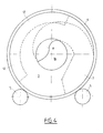
- the churn comprises a screen 12 which, in the embodiment shown, is welded to the internal wall of the neck 3.
- This screen 12 is visible in FIG. 4 in which, the pivoting counter blade 9 has not been intentionally shown, for the clarity of this FIG. 4.
- the rollers 5 and the belt 4 we can see the rollers 5 and the belt 4, the helical blade 8 and the blade 7. It will be noted that the screen 12 is placed behind the helical blade 8, as is also visible in FIG. 1.
- FIGS. 5a and 5b we will now explain the operation of a churn according to the invention and this, in relation to FIGS. 5a and 5b.
- FIGS. 5a and 5b only the tank 1 and the counterblade 9 and its pivot axis 10 are shown, in a single plane transverse. This plane is for example that of section II / II in FIG. 1. It has been shown by corrugations that the tank 1 contains a product P.
- FIG. 5a the tank 1 is subjected to a rotation in the direction shown by an arrow A. This direction corresponds to that which is used during the operation of mixing the product P contained in the tank 1.
- FIG. 5a the tank 1 is subjected to a rotation in the direction shown by an arrow A. This direction corresponds to that which is used during the operation of mixing the product P contained in the tank 1.
- FIG. 5a the tank 1 is subjected to a rotation in the direction shown by an arrow A. This direction corresponds to that which is used during the operation of mixing the product P
- the tank 1 is subjected to a rotation in the opposite direction shown by an arrow B corresponding to the direction used during the operation of extracting the product P from the churn by its opening 3a.
- an arrow B corresponding to the direction used during the operation of extracting the product P from the churn by its opening 3a.
- FIGs. 5a and 5b there are shown eight different counter blade positions, marked by Roman numerals I to VIII.
- Fig. 5a In position I, the counter blade 9, by its own weight, is placed vertically with its free edge 9a which is distant from the internal wall of the tank 1. It keeps this vertical position, in position II, where its end free begins to penetrate into the product contained in the tank 1. In position III, the counter blade 9 is subjected to the action of the product P, action symbolized by the arrow Ac, which has the effect of rotating it according to the arrow p . At position IV, it has completely pivoted and finds itself in abutment on the internal wall of the tank 1.
- the counter blade 9 finds itself in an unstable position where, in a way pushed by the stop 13, it pivots to find itself vertical with its free edge opposite the wall of the tank 1. This pivoting is symbolized by an arrow marked q .
- the counter blade 9 remains in this open position as long as it is immersed in the product P contained in the tank 1, that is to say in positions III to VI. It will be noted that the two faces of the counter blade 9 are, in these positions, licked by the product P contained in the tank 1 so that no product can agglomerate on these faces.
- the screen 12 has an action in the direction of rotation of the churn which corresponds to stirring since it is located behind the helical blade 8. On the other hand, for the same reason, it has no action in the direction of rotation of the churn which corresponds to the extraction of the product.
- the action of the screen 12 may prove to be insufficient to avoid pushing the product towards the rear of the churn. Also, it may prove necessary to provide two counterblades 9 and 9 ′ oriented in the same way, advantageously at the same angle, as shown in dotted lines in FIG. 3.
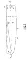
- FIG. 6 a second embodiment has been provided, which is shown in FIG. 6 and which provides for the use of a counter blade 90 which can also be seen in FIG. 7.
- This counter blade 90 is provided with an edge 91 which is intended to come into contact with the internal wall of the tank 1.
- the area of the part 92 is greater than the area of the part 93. To do this, the distance W from the axis tt 'to the edge 91 is greater than the distance V from the axis tt' to the edge opposite the edge 91.
- the part 93 is further provided with a counterweight 94 which allows the part 93 to be heavier than the part 92.
- the counter blade 90 has a natural tendency to present itself vertically with the edge 91 turned towards the top, that is to say the reverse of what is shown in FIG. 7.
- the pivot axis of the counter blade is located along the edge opposite the edge intended to rest on the wall of the tank 1.
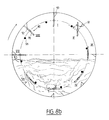
- FIGs. 8a and 8b there is also shown a stop 97 on which the counter blade 90 bears when its edge 91 rests on the wall of the tank 1. It will be noted that other means than a stop 97 could also be provided for stop the counter blade 90 on the wall of the tank 1.
- the heaviest part 93 of the counterblade 90 has also been marked with a + sign.
- Fig. 8a corresponds to the mixing phase of the churn.
- the counter blade 90 is positioned naturally stopped by the stop 97 so that its heaviest part 93 is turned downwards.
- the counter blade 90 At the time of the attack in the product in position III, the counter blade 90 is in abutment, the edge 91 then resting on the internal wall of the tank 1. It will be noted that the counter blade 90 is then already in place and it is immediately active.
- the counter blade 90 undergoes the action of the product, on the one hand, on its part 92 between the pivot axis tt 'and the edge 91 and, on the other hand, on its part 93 between the pivot axis tt 'and the edge opposite to the edge 91.
- the lines of circulation of the product under the action of the counter blade 90 are shown by arrows. Because the part 92 has a larger area than on the part 93, the forces resulting from the pressures on the counter blade 90, are greater on the part 92 than on the part 93. As a result, the counter blade 90 keeps its position in abutment against the wall of the tank 1 as long as it is in the product, that is to say from position III to position VII.
- FIG. 8b relates to the emptying of the tank 1.
- the counter blade In positions I and II, the counter blade is naturally placed vertically with its heaviest part 93 turned downwards. It enters the product vertically (position III).
- positions IV to VII the pressure balance on the two faces of the counter blade 90 is such that the latter remains substantially parallel to a tangent to the wall of the tank 1. It therefore has no action on the product contained in the tank 1.
- the product circulation lines have also been shown and it can be seen that they are substantially parallel to the counter blade 90.
- the counter blade 90 turns in the direction of the arrow D so as to be again in abutment. It keeps this position in VIII.
- This embodiment is particularly advantageous insofar as the action of the counter blade 90, in the mixing phase, takes place as soon as it enters the product, which was not the case in the first embodiment. . It follows that the product is not beaten and that this embodiment is particularly well suited to products of fragile structure.
Landscapes
- Chemical & Material Sciences (AREA)
- Chemical Kinetics & Catalysis (AREA)
- Organic Chemistry (AREA)
- Engineering & Computer Science (AREA)
- Mechanical Engineering (AREA)
- Structural Engineering (AREA)
- Mixers Of The Rotary Stirring Type (AREA)
- Food-Manufacturing Devices (AREA)
- Gas Burners (AREA)
- Photoreceptors In Electrophotography (AREA)
- Biological Depolymerization Polymers (AREA)
- Radiation-Therapy Devices (AREA)
- Cleaning Implements For Floors, Carpets, Furniture, Walls, And The Like (AREA)
- Vaporization, Distillation, Condensation, Sublimation, And Cold Traps (AREA)
- Catching Or Destruction (AREA)
- Soil Working Implements (AREA)
Applications Claiming Priority (4)
| Application Number | Priority Date | Filing Date | Title |
|---|---|---|---|
| FR9605476A FR2747891B1 (fr) | 1996-04-25 | 1996-04-25 | Baratte utilisable dans le domaine de l'agroalimentaire |
| FR9605476 | 1996-04-25 | ||
| FR9611401A FR2747892B3 (fr) | 1996-04-25 | 1996-09-13 | Baratte utilisable dans le domaine de l'agroalimentaire |
| FR9611401 | 1996-09-13 |
Publications (2)
| Publication Number | Publication Date |
|---|---|
| EP0803282A1 true EP0803282A1 (de) | 1997-10-29 |
| EP0803282B1 EP0803282B1 (de) | 2001-07-04 |
Family
ID=26232683
Family Applications (1)
| Application Number | Title | Priority Date | Filing Date |
|---|---|---|---|
| EP97460014A Expired - Lifetime EP0803282B1 (de) | 1996-04-25 | 1997-03-27 | Drehtrommel für die Landwirtschaft und Nahrungsmittelindustrie |
Country Status (5)
| Country | Link |
|---|---|
| EP (1) | EP0803282B1 (de) |
| AT (1) | ATE202724T1 (de) |
| DE (1) | DE69705457D1 (de) |
| ES (1) | ES2160313T3 (de) |
| FR (1) | FR2747892B3 (de) |
Cited By (6)
| Publication number | Priority date | Publication date | Assignee | Title |
|---|---|---|---|---|
| FR2773675A1 (fr) * | 1998-01-20 | 1999-07-23 | Armor Inox Sa | Baratte utilisable dans le domaine de l'agroalimentaire |
| EP1205112A1 (de) * | 2000-11-14 | 2002-05-15 | Armor Inox | Drehtrommel zur Behandlung von Nahrungsmitteln wie Fleisch und Fisch |
| FR2816484A1 (fr) * | 2000-11-15 | 2002-05-17 | Armor Inox Sa | Baratte de traitement pour produits alimentaires |
| CN103432938A (zh) * | 2013-08-30 | 2013-12-11 | 辽宁海诺建设机械集团有限公司 | 一种连续式滚筒搅拌机及其使用方法 |
| CN105563653A (zh) * | 2015-08-24 | 2016-05-11 | 朱小菊 | 节能型自落式混凝土混匀机 |
| CN112449994A (zh) * | 2020-11-25 | 2021-03-09 | 王峰 | 一种香菇工厂化制棒工艺及其设备 |
Families Citing this family (1)
| Publication number | Priority date | Publication date | Assignee | Title |
|---|---|---|---|---|
| CN101927151B (zh) * | 2010-09-17 | 2012-06-13 | 苏忠 | 具有输送功能的热反应器 |
Citations (5)
| Publication number | Priority date | Publication date | Assignee | Title |
|---|---|---|---|---|
| DE249795C (de) * | ||||
| FR726959A (fr) * | 1931-11-27 | 1932-06-10 | Agitateur pour bétonnières ou autres appareils similaires | |
| US1866688A (en) * | 1928-11-23 | 1932-07-12 | Transit Mixers Inc | Mixing or agitating device |
| GB679132A (en) * | 1949-11-10 | 1952-09-10 | Nat Res Dev | Improvements in and relating to rotating drum mixers |
| EP0188674A1 (de) * | 1984-12-28 | 1986-07-30 | Friedrich Wilh. Schwing GmbH | Fahrmischer, vorzugsweise mit Gegenlaufentleerung für Baustoffe, insbesondere Beton |
-
1996
- 1996-09-13 FR FR9611401A patent/FR2747892B3/fr not_active Expired - Lifetime
-
1997
- 1997-03-27 ES ES97460014T patent/ES2160313T3/es not_active Expired - Lifetime
- 1997-03-27 EP EP97460014A patent/EP0803282B1/de not_active Expired - Lifetime
- 1997-03-27 AT AT97460014T patent/ATE202724T1/de not_active IP Right Cessation
- 1997-03-27 DE DE69705457T patent/DE69705457D1/de not_active Expired - Lifetime
Patent Citations (5)
| Publication number | Priority date | Publication date | Assignee | Title |
|---|---|---|---|---|
| DE249795C (de) * | ||||
| US1866688A (en) * | 1928-11-23 | 1932-07-12 | Transit Mixers Inc | Mixing or agitating device |
| FR726959A (fr) * | 1931-11-27 | 1932-06-10 | Agitateur pour bétonnières ou autres appareils similaires | |
| GB679132A (en) * | 1949-11-10 | 1952-09-10 | Nat Res Dev | Improvements in and relating to rotating drum mixers |
| EP0188674A1 (de) * | 1984-12-28 | 1986-07-30 | Friedrich Wilh. Schwing GmbH | Fahrmischer, vorzugsweise mit Gegenlaufentleerung für Baustoffe, insbesondere Beton |
Cited By (9)
| Publication number | Priority date | Publication date | Assignee | Title |
|---|---|---|---|---|
| FR2773675A1 (fr) * | 1998-01-20 | 1999-07-23 | Armor Inox Sa | Baratte utilisable dans le domaine de l'agroalimentaire |
| EP1205112A1 (de) * | 2000-11-14 | 2002-05-15 | Armor Inox | Drehtrommel zur Behandlung von Nahrungsmitteln wie Fleisch und Fisch |
| FR2816484A1 (fr) * | 2000-11-15 | 2002-05-17 | Armor Inox Sa | Baratte de traitement pour produits alimentaires |
| CN103432938A (zh) * | 2013-08-30 | 2013-12-11 | 辽宁海诺建设机械集团有限公司 | 一种连续式滚筒搅拌机及其使用方法 |
| CN103432938B (zh) * | 2013-08-30 | 2015-06-10 | 辽宁海诺建设机械集团有限公司 | 一种连续式滚筒搅拌机及其使用方法 |
| CN105563653A (zh) * | 2015-08-24 | 2016-05-11 | 朱小菊 | 节能型自落式混凝土混匀机 |
| CN105563653B (zh) * | 2015-08-24 | 2017-12-01 | 新昌县羽林街道全顺机械厂 | 节能型自落式混凝土混匀机 |
| CN112449994A (zh) * | 2020-11-25 | 2021-03-09 | 王峰 | 一种香菇工厂化制棒工艺及其设备 |
| CN112449994B (zh) * | 2020-11-25 | 2022-03-08 | 王峰 | 一种香菇工厂化制棒工艺及其设备 |
Also Published As
| Publication number | Publication date |
|---|---|
| ES2160313T3 (es) | 2001-11-01 |
| DE69705457D1 (de) | 2001-08-09 |
| FR2747892B3 (fr) | 1998-06-05 |
| ATE202724T1 (de) | 2001-07-15 |
| EP0803282B1 (de) | 2001-07-04 |
| FR2747892A1 (fr) | 1997-10-31 |
Similar Documents
| Publication | Publication Date | Title |
|---|---|---|
| EP1097086B1 (de) | Lösbare hülse zum öffnen und wiederverschliessen einer getränke dose mit aufreisslasche | |
| CH622713A5 (de) | ||
| FR2507573A1 (fr) | Recipient pour boisson perforable par une paille | |
| EP0253719B1 (de) | Einfüllschacht an einer Maschine zum Behandeln von Nahrungsmitteln | |
| EP0803282B1 (de) | Drehtrommel für die Landwirtschaft und Nahrungsmittelindustrie | |
| FR2498574A1 (fr) | Sas a roue cellulaire | |
| FR2723752A1 (fr) | Recipient doseur et diffuseur de produits de lavage | |
| EP0164277B1 (de) | Verfahren und Vorrichtung zum Erhalten eines unter hohem Vakuum verpackten wässerigen Nahrungsmittels | |
| EP2039619B1 (de) | Herstellungsverfahren eines Beutels aus einer Plastikfolienrolle | |
| EP0364373B1 (de) | Biegsamer Behälter | |
| FR2747891A1 (fr) | Baratte utilisable dans le domaine de l'agroalimentaire | |
| LU85206A1 (fr) | Procede de fabrication de produits a base de cereales a cavite remplie et produits obtenus par ce procede | |
| FR2486384A1 (fr) | Appareil pour la preparation d'aliments, notamment pour le travail de pates | |
| EP0500903A1 (de) | Rotierende trocken composttoilette. | |
| EP0027091B1 (de) | Schaupackung | |
| EP3912526B1 (de) | Rührblatt zum rühren von lebensmitteln für kochgerät und entsprechendes gerät | |
| FR2605612A1 (fr) | Dispositif d'acheminement de pieces avec ou sans retournement en vue de leur empilage | |
| FR2827206A1 (fr) | Procede et dispositif de formage de planchettes, et emballages comportant de telles planchettes | |
| EP3845103B1 (de) | Mischvorrichtung | |
| FR2763315A1 (fr) | Procede d'ouverture et de rebouchage d'une boite a boisson munie d'un obturateur frangible utilisant un etui amovible et dispositif le mettant en oeuvre | |
| EP0475867B1 (de) | Wäscher-Tür für Massagevorrichtung | |
| FR2659189A3 (fr) | Hacheuse a tambour ou a disque. | |
| EP0898448A1 (de) | Aufnahme,misch,undverteilmaschine fur futter | |
| FR2889974A1 (fr) | Essoreuse discontinue, notamment prevue pour separer la melasse des cristaux de sucre d'une masse cuite | |
| FR3106047A1 (fr) | Machine de preparation de boisson infusee munie d’une carafe agencee sur une base de reception |
Legal Events
| Date | Code | Title | Description |
|---|---|---|---|
| PUAI | Public reference made under article 153(3) epc to a published international application that has entered the european phase |
Free format text: ORIGINAL CODE: 0009012 |
|
| AK | Designated contracting states |
Kind code of ref document: A1 Designated state(s): AT BE CH DE DK ES FR GB IT LI NL |
|
| 17P | Request for examination filed |
Effective date: 19980218 |
|
| 17Q | First examination report despatched |
Effective date: 20000419 |
|
| GRAG | Despatch of communication of intention to grant |
Free format text: ORIGINAL CODE: EPIDOS AGRA |
|
| GRAG | Despatch of communication of intention to grant |
Free format text: ORIGINAL CODE: EPIDOS AGRA |
|
| GRAH | Despatch of communication of intention to grant a patent |
Free format text: ORIGINAL CODE: EPIDOS IGRA |
|
| GRAH | Despatch of communication of intention to grant a patent |
Free format text: ORIGINAL CODE: EPIDOS IGRA |
|
| GRAA | (expected) grant |
Free format text: ORIGINAL CODE: 0009210 |
|
| AK | Designated contracting states |
Kind code of ref document: B1 Designated state(s): AT BE CH DE DK ES FR GB IT LI NL |
|
| PG25 | Lapsed in a contracting state [announced via postgrant information from national office to epo] |
Ref country code: NL Free format text: LAPSE BECAUSE OF FAILURE TO SUBMIT A TRANSLATION OF THE DESCRIPTION OR TO PAY THE FEE WITHIN THE PRESCRIBED TIME-LIMIT Effective date: 20010704 Ref country code: IT Free format text: LAPSE BECAUSE OF FAILURE TO SUBMIT A TRANSLATION OF THE DESCRIPTION OR TO PAY THE FEE WITHIN THE PRESCRIBED TIME-LIMIT;WARNING: LAPSES OF ITALIAN PATENTS WITH EFFECTIVE DATE BEFORE 2007 MAY HAVE OCCURRED AT ANY TIME BEFORE 2007. THE CORRECT EFFECTIVE DATE MAY BE DIFFERENT FROM THE ONE RECORDED. Effective date: 20010704 Ref country code: AT Free format text: LAPSE BECAUSE OF FAILURE TO SUBMIT A TRANSLATION OF THE DESCRIPTION OR TO PAY THE FEE WITHIN THE PRESCRIBED TIME-LIMIT Effective date: 20010704 |
|
| REF | Corresponds to: |
Ref document number: 202724 Country of ref document: AT Date of ref document: 20010715 Kind code of ref document: T |
|
| REG | Reference to a national code |
Ref country code: CH Ref legal event code: EP |
|
| GBT | Gb: translation of ep patent filed (gb section 77(6)(a)/1977) |
Effective date: 20010706 |
|
| REF | Corresponds to: |
Ref document number: 69705457 Country of ref document: DE Date of ref document: 20010809 |
|
| PG25 | Lapsed in a contracting state [announced via postgrant information from national office to epo] |
Ref country code: DK Free format text: LAPSE BECAUSE OF FAILURE TO SUBMIT A TRANSLATION OF THE DESCRIPTION OR TO PAY THE FEE WITHIN THE PRESCRIBED TIME-LIMIT Effective date: 20011004 |
|
| PG25 | Lapsed in a contracting state [announced via postgrant information from national office to epo] |
Ref country code: DE Free format text: LAPSE BECAUSE OF FAILURE TO SUBMIT A TRANSLATION OF THE DESCRIPTION OR TO PAY THE FEE WITHIN THE PRESCRIBED TIME-LIMIT Effective date: 20011005 |
|
| REG | Reference to a national code |
Ref country code: ES Ref legal event code: FG2A Ref document number: 2160313 Country of ref document: ES Kind code of ref document: T3 |
|
| NLV1 | Nl: lapsed or annulled due to failure to fulfill the requirements of art. 29p and 29m of the patents act | ||
| REG | Reference to a national code |
Ref country code: GB Ref legal event code: IF02 |
|
| PG25 | Lapsed in a contracting state [announced via postgrant information from national office to epo] |
Ref country code: LI Free format text: LAPSE BECAUSE OF NON-PAYMENT OF DUE FEES Effective date: 20020331 Ref country code: CH Free format text: LAPSE BECAUSE OF NON-PAYMENT OF DUE FEES Effective date: 20020331 Ref country code: BE Free format text: LAPSE BECAUSE OF NON-PAYMENT OF DUE FEES Effective date: 20020331 |
|
| PLBE | No opposition filed within time limit |
Free format text: ORIGINAL CODE: 0009261 |
|
| STAA | Information on the status of an ep patent application or granted ep patent |
Free format text: STATUS: NO OPPOSITION FILED WITHIN TIME LIMIT |
|
| 26N | No opposition filed | ||
| BERE | Be: lapsed |
Owner name: S.A. *ARMOR INOX Effective date: 20020331 |
|
| REG | Reference to a national code |
Ref country code: CH Ref legal event code: PL |
|
| PGFP | Annual fee paid to national office [announced via postgrant information from national office to epo] |
Ref country code: GB Payment date: 20110321 Year of fee payment: 15 Ref country code: ES Payment date: 20110325 Year of fee payment: 15 |
|
| GBPC | Gb: european patent ceased through non-payment of renewal fee |
Effective date: 20120327 |
|
| PG25 | Lapsed in a contracting state [announced via postgrant information from national office to epo] |
Ref country code: GB Free format text: LAPSE BECAUSE OF NON-PAYMENT OF DUE FEES Effective date: 20120327 |
|
| REG | Reference to a national code |
Ref country code: ES Ref legal event code: FD2A Effective date: 20130711 |
|
| PG25 | Lapsed in a contracting state [announced via postgrant information from national office to epo] |
Ref country code: ES Free format text: LAPSE BECAUSE OF NON-PAYMENT OF DUE FEES Effective date: 20120328 |
|
| PGFP | Annual fee paid to national office [announced via postgrant information from national office to epo] |
Ref country code: FR Payment date: 20140328 Year of fee payment: 18 |
|
| REG | Reference to a national code |
Ref country code: FR Ref legal event code: ST Effective date: 20151130 |
|
| PG25 | Lapsed in a contracting state [announced via postgrant information from national office to epo] |
Ref country code: FR Free format text: LAPSE BECAUSE OF NON-PAYMENT OF DUE FEES Effective date: 20150331 |