EP0803258B1 - Absaugpumpe - Google Patents
Absaugpumpe Download PDFInfo
- Publication number
- EP0803258B1 EP0803258B1 EP97104032A EP97104032A EP0803258B1 EP 0803258 B1 EP0803258 B1 EP 0803258B1 EP 97104032 A EP97104032 A EP 97104032A EP 97104032 A EP97104032 A EP 97104032A EP 0803258 B1 EP0803258 B1 EP 0803258B1
- Authority
- EP
- European Patent Office
- Prior art keywords
- suction removal
- lever
- hollow space
- movable
- pump according
- Prior art date
- Legal status (The legal status is an assumption and is not a legal conclusion. Google has not performed a legal analysis and makes no representation as to the accuracy of the status listed.)
- Expired - Lifetime
Links
- 239000012080 ambient air Substances 0.000 claims description 2
- 239000011796 hollow space material Substances 0.000 claims 6
- 238000004140 cleaning Methods 0.000 description 3
- 239000000463 material Substances 0.000 description 3
- 238000000034 method Methods 0.000 description 2
- 230000028327 secretion Effects 0.000 description 2
- 210000001124 body fluid Anatomy 0.000 description 1
- 239000010839 body fluid Substances 0.000 description 1
- 230000006835 compression Effects 0.000 description 1
- 238000007906 compression Methods 0.000 description 1
- 230000001419 dependent effect Effects 0.000 description 1
- 238000011161 development Methods 0.000 description 1
- 230000018109 developmental process Effects 0.000 description 1
- 230000003670 easy-to-clean Effects 0.000 description 1
- 239000007788 liquid Substances 0.000 description 1
- 230000000737 periodic effect Effects 0.000 description 1
- 238000005086 pumping Methods 0.000 description 1
- 210000004916 vomit Anatomy 0.000 description 1
- 230000008673 vomiting Effects 0.000 description 1
Images

Classifications
-
- A—HUMAN NECESSITIES
- A61—MEDICAL OR VETERINARY SCIENCE; HYGIENE
- A61M—DEVICES FOR INTRODUCING MEDIA INTO, OR ONTO, THE BODY; DEVICES FOR TRANSDUCING BODY MEDIA OR FOR TAKING MEDIA FROM THE BODY; DEVICES FOR PRODUCING OR ENDING SLEEP OR STUPOR
- A61M1/00—Suction or pumping devices for medical purposes; Devices for carrying-off, for treatment of, or for carrying-over, body-liquids; Drainage systems
- A61M1/64—Containers with integrated suction means
- A61M1/68—Containers incorporating a flexible member creating suction
- A61M1/684—Containers incorporating a flexible member creating suction bellows-type
-
- A—HUMAN NECESSITIES
- A61—MEDICAL OR VETERINARY SCIENCE; HYGIENE
- A61M—DEVICES FOR INTRODUCING MEDIA INTO, OR ONTO, THE BODY; DEVICES FOR TRANSDUCING BODY MEDIA OR FOR TAKING MEDIA FROM THE BODY; DEVICES FOR PRODUCING OR ENDING SLEEP OR STUPOR
- A61M2205/00—General characteristics of the apparatus
- A61M2205/07—General characteristics of the apparatus having air pumping means
- A61M2205/078—General characteristics of the apparatus having air pumping means foot operated
-
- Y—GENERAL TAGGING OF NEW TECHNOLOGICAL DEVELOPMENTS; GENERAL TAGGING OF CROSS-SECTIONAL TECHNOLOGIES SPANNING OVER SEVERAL SECTIONS OF THE IPC; TECHNICAL SUBJECTS COVERED BY FORMER USPC CROSS-REFERENCE ART COLLECTIONS [XRACs] AND DIGESTS
- Y10—TECHNICAL SUBJECTS COVERED BY FORMER USPC
- Y10S—TECHNICAL SUBJECTS COVERED BY FORMER USPC CROSS-REFERENCE ART COLLECTIONS [XRACs] AND DIGESTS
- Y10S417/00—Pumps
- Y10S417/903—Treadle operated
Definitions
- the invention relates to a suction pump, in particular for medical purposes, with a Receptacle with two chambers arranged side by side, with a suction hose are connected and on each of which an approximately parallel movable, one Cavity partially surrounding element is arranged to create a vacuum, wherein the two movable elements are connected by a lever, the two of which End parts are each supported on the upper area of a movable element and its Middle part is movably supported in a storage arranged between the chambers and a one-way valve is arranged in the upper region of each movable element, which opens when the pressure in the cavity is greater than the ambient air pressure.
- Such a suction pump is known for example from EP 245 876.
- Pump With the described here Pump are two receptacles connected to each other via a U-shaped connector connected.
- the two movable ones arranged side by side Pump elements are connected to each other via a common lever, so that with each lever movement one of the two movable elements creates a vacuum Suction generated by the catheter. This results in dead times when operating the pump avoided.
- the pump is very reliable, but also relatively complex.
- the cleaning of the pump that is required after each suction requires a very complex one Disassembly.
- Both receptacles are openly connected to each other, so that with every lifting movement in a relatively large volume vacuum through a relatively small stroke each a movable element is generated.
- a completely different type of suction pump is known from EP 271 620.
- the one described here hand operated pump has a single cavity in which Vacuum is created to extract body fluids and the like.
- the manual control requires a relatively high mechanical effort, for example through the use of Return springs. Due to the alternating suction times when operating this pump and dead times, continuous suction is not possible, so that the suction process accordingly slow. In addition, the periodic interruption of the suction process a check valve at the distal end of the catheter is necessary. Furthermore working with this pump is quite tiring in the long run, because the one necessary for suction Work done only by opening and closing the operator's hand becomes.
- the object of the present invention is based on the disadvantages of the described State of the art to provide a suction pump that is both easy to use and is also easy to clean and enables safe suction.
- Such a suction pump comes with a minimum of parts because the entire cavity is delimited by a uniform material can, wherein the movable element is preferably designed as a bellows.
- the container can be manufactured easily and therefore inexpensively and can be designed as a disposable container, so that cleaning after use is not necessary, since the container with its Content can be disposed of.
- the lever can expediently be designed as a tread plate, so that by a back and forth Movement of an operator's foot on the lever alternating the vacuum in both Cavities is formed.
- the lever is expediently releasable on the movable Elements held to facilitate cleaning or reuse of the Lever when disposing of the receptacle designed as a disposable container enable.
- the receptacle is held in a basic housing, the one Has base plate and side walls and that the base housing the storage for the lever having. A particularly high stability of the suction pump can thereby be achieved.
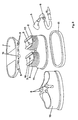
- the suction pump has a receptacle with two chambers arranged side by side 1, the top of which is bounded by a movable element.
- the mobile Element 2 is used to generate the vacuum in the of the receptacle 1 and the movable element 2 formed common cavity.
- a one-way valve 3 is arranged, which opens when the bellows is compressed, so that by the compression resulting excess pressure is reduced inside the cavity. While When one bellows is pressed down, the second bellows next to it becomes the same Bellows pulled apart so that a negative pressure is created in the corresponding cavity.
- This negative pressure opens the second one-way valve 4, so that in the distributor pipe 5 and the suction hose 6 connected to it, a vacuum is formed and as a result from a body cavity, for example the mouth of an emergency patient, secretion or similar can be suctioned off.
- the lifting or lowering movement takes place by means of the lever 7, which is designed as a tread plate and which Bearing pin 15 is movably supported in a bearing 8.
- the lever 7 At the bottom of the lever 7 recesses 9 are arranged, on which the lever 7 on corresponding counterparts 10th is pushed onto the upper sides of the movable elements 2. The lever 7 can thereby can be removed very easily from the movable elements 2 of the suction pump.
- the receptacle with the chambers 1 is integrated in a housing 11 (see Figure 2).
- This housing 11 is arranged and received on a base plate 12 in the basic housing 13 thereby high stability.
- the connection of the base plate 12 and side walls 14 of the basic housing 13 with the housing 11 can be snapped together the edges of the individual parts are made if they are made of a material with sufficient flexibility, such as an elastic plastic.
- the lever 7 is in the bearing 8 arranged in the basic housing 13 is supported.
- Such a suction pump is very easy to assemble.
- this can Unit can be easily removed from the basic housing 13 and disposed of while the Basic housing 13 and the lever 7 can be easily cleaned and reused.
Landscapes
- Health & Medical Sciences (AREA)
- Heart & Thoracic Surgery (AREA)
- Animal Behavior & Ethology (AREA)
- General Health & Medical Sciences (AREA)
- Anesthesiology (AREA)
- Biomedical Technology (AREA)
- Hematology (AREA)
- Life Sciences & Earth Sciences (AREA)
- Vascular Medicine (AREA)
- Engineering & Computer Science (AREA)
- Public Health (AREA)
- Veterinary Medicine (AREA)
- External Artificial Organs (AREA)
- Reciprocating Pumps (AREA)
- Details Of Reciprocating Pumps (AREA)
- Earth Drilling (AREA)
- Transition And Organic Metals Composition Catalysts For Addition Polymerization (AREA)
- Liquid Crystal Substances (AREA)
Applications Claiming Priority (2)
| Application Number | Priority Date | Filing Date | Title |
|---|---|---|---|
| DE19616954A DE19616954C2 (de) | 1996-04-27 | 1996-04-27 | Absaugpumpe |
| DE19616954 | 1996-04-27 |
Publications (3)
| Publication Number | Publication Date |
|---|---|
| EP0803258A2 EP0803258A2 (de) | 1997-10-29 |
| EP0803258A3 EP0803258A3 (de) | 1998-08-12 |
| EP0803258B1 true EP0803258B1 (de) | 2002-11-06 |
Family
ID=7792675
Family Applications (1)
| Application Number | Title | Priority Date | Filing Date |
|---|---|---|---|
| EP97104032A Expired - Lifetime EP0803258B1 (de) | 1996-04-27 | 1997-03-11 | Absaugpumpe |
Country Status (7)
| Country | Link |
|---|---|
| US (1) | US5934888A (da) |
| EP (1) | EP0803258B1 (da) |
| JP (1) | JPH1061546A (da) |
| DE (2) | DE19616954C2 (da) |
| DK (1) | DK0803258T3 (da) |
| IL (1) | IL120454A0 (da) |
| NO (1) | NO971586L (da) |
Families Citing this family (13)
| Publication number | Priority date | Publication date | Assignee | Title |
|---|---|---|---|---|
| US7172572B2 (en) | 2001-10-04 | 2007-02-06 | Boston Scientific Scimed, Inc. | Manifold system for a medical device |
| US9956377B2 (en) | 2002-09-20 | 2018-05-01 | Angiodynamics, Inc. | Method and apparatus for intra-aortic substance delivery to a branch vessel |
| RU2252037C1 (ru) * | 2003-10-14 | 2005-05-20 | Германов Евгений Павлович | Система коррекции биологической жидкости |
| EP1627670B1 (en) * | 2004-08-16 | 2009-09-30 | Aruze Corp. | Roulette apparatus and roulette gaming machine |
| ATE396753T1 (de) | 2005-12-05 | 2008-06-15 | Hersill S L | Medizinisches absauggerät |
| US20080301865A1 (en) * | 2007-06-11 | 2008-12-11 | Robert Hand | Toilet ventilation system and associated method |
| RU2354410C1 (ru) * | 2007-12-13 | 2009-05-10 | Ооо "Медплант" | Аспиратор портативный с механическим приводом |
| KR20100129764A (ko) * | 2008-03-13 | 2010-12-09 | 케이씨아이 라이센싱 인코포레이티드 | 감압 충전 시스템 및 방법 |
| WO2011100430A2 (en) | 2010-02-10 | 2011-08-18 | Kickstart International, Inc. | Human-powered irrigation pump |
| EP2897673B1 (en) | 2012-09-24 | 2020-01-22 | Medline Industries, Inc. | Power injector device and method of use |
| US11369739B2 (en) | 2013-01-21 | 2022-06-28 | Medline Industries, Lp | Method to provide injection system parameters for injecting fluid into patient |
| CN108374779A (zh) * | 2018-04-26 | 2018-08-07 | 李则穰 | 一种洗车用脚踩式水泵 |
| DE102024000719A1 (de) * | 2024-03-04 | 2025-09-04 | Hydac Technology Gmbh | Fördervorrichtung |
Family Cites Families (5)
| Publication number | Priority date | Publication date | Assignee | Title |
|---|---|---|---|---|
| US2707001A (en) * | 1951-03-27 | 1955-04-26 | Hathaway Instr Company | Balanced bellows pressure head |
| US4643719A (en) * | 1984-07-19 | 1987-02-17 | Garth Geoffrey C | Manually operable aspirator |
| DK156028C (da) * | 1986-05-16 | 1989-11-06 | Testa Lab A S | Aspirator |
| DE3811698A1 (de) * | 1988-04-05 | 1989-10-19 | Molt Werner Dipl Designer | Luftpumpe fuer pruefroehrchen |
| US5304129A (en) * | 1993-07-12 | 1994-04-19 | Forgach Suzanne E | Pivotable foot operated breast pump |
-
1996
- 1996-04-27 DE DE19616954A patent/DE19616954C2/de not_active Expired - Fee Related
-
1997
- 1997-03-11 EP EP97104032A patent/EP0803258B1/de not_active Expired - Lifetime
- 1997-03-11 DK DK97104032T patent/DK0803258T3/da active
- 1997-03-11 DE DE59708643T patent/DE59708643D1/de not_active Expired - Fee Related
- 1997-03-14 IL IL12045497A patent/IL120454A0/xx unknown
- 1997-04-07 NO NO971586A patent/NO971586L/no not_active Application Discontinuation
- 1997-04-18 US US08/844,298 patent/US5934888A/en not_active Expired - Fee Related
- 1997-04-24 JP JP9106959A patent/JPH1061546A/ja active Pending
Also Published As
| Publication number | Publication date |
|---|---|
| EP0803258A2 (de) | 1997-10-29 |
| NO971586L (no) | 1997-10-28 |
| DE19616954C2 (de) | 2000-02-10 |
| DK0803258T3 (da) | 2003-03-03 |
| US5934888A (en) | 1999-08-10 |
| NO971586D0 (no) | 1997-04-07 |
| JPH1061546A (ja) | 1998-03-03 |
| EP0803258A3 (de) | 1998-08-12 |
| IL120454A0 (en) | 1997-07-13 |
| DE19616954A1 (de) | 1997-11-06 |
| DE59708643D1 (de) | 2002-12-12 |
Similar Documents
| Publication | Publication Date | Title |
|---|---|---|
| EP0803258B1 (de) | Absaugpumpe | |
| DE3784095T2 (de) | Absauger. | |
| EP1184042B1 (de) | Absaugpumpe | |
| AT509749B1 (de) | Spender | |
| DE68903665T2 (de) | Balg-pipette und ihre verwendung. | |
| EP0576438A1 (de) | Hochdruckreinigungsgerät. | |
| EP1467781A1 (de) | Dentales behandlungsger t | |
| DE3605419A1 (de) | Dosierspender | |
| DE3008346A1 (de) | Pipette | |
| DE2706303C2 (de) | Saugvorrichtung zur pneumatischen Betätigung von Blutentnahmevorrichtungen | |
| DE202016103320U1 (de) | Feuchtreinigungsgerät | |
| EP1010387B1 (de) | Filtervorrichtung mit Rüttler | |
| DE20301533U1 (de) | Klobürste | |
| DE2410910A1 (de) | Injektionsspritze | |
| DE29704742U1 (de) | Hartflächen-Reinigungsgerät | |
| DE3332502A1 (de) | Volumetrische verduennungsvorrichtung | |
| DE3400945A1 (de) | Zentralverriegelungsanlage eines kraftfahrzeugs | |
| EP1133948B1 (de) | Elekrosauggerät, insbesondere für Staub | |
| DE2846507C3 (de) | Selbsttätige Schuhbelüftungseinrichtung mit selbstreinigendem Luftfilter | |
| DE19946707C2 (de) | Absaugvorrichtung zum Absaugen von flüssigen Überständen aus offenen Behältnissen | |
| EP0922939A2 (de) | Flaschendosierer | |
| DE3008347A1 (de) | Serienpipette | |
| EP0638721A1 (de) | Förderpumpe | |
| EP1639931A2 (de) | Gehäuseunterteil eines Handstaubsaugers | |
| DE4215447C2 (de) | Staubfiltersack |
Legal Events
| Date | Code | Title | Description |
|---|---|---|---|
| PUAI | Public reference made under article 153(3) epc to a published international application that has entered the european phase |
Free format text: ORIGINAL CODE: 0009012 |
|
| 17P | Request for examination filed |
Effective date: 19970325 |
|
| AK | Designated contracting states |
Kind code of ref document: A2 Designated state(s): DE DK FR IT SE |
|
| PUAL | Search report despatched |
Free format text: ORIGINAL CODE: 0009013 |
|
| AK | Designated contracting states |
Kind code of ref document: A3 Designated state(s): DE DK FR IT SE |
|
| RAP1 | Party data changed (applicant data changed or rights of an application transferred) |
Owner name: WERO-MEDICAL WERNER MICHALLIK GMBH & CO. KG |
|
| GRAG | Despatch of communication of intention to grant |
Free format text: ORIGINAL CODE: EPIDOS AGRA |
|
| GRAG | Despatch of communication of intention to grant |
Free format text: ORIGINAL CODE: EPIDOS AGRA |
|
| GRAH | Despatch of communication of intention to grant a patent |
Free format text: ORIGINAL CODE: EPIDOS IGRA |
|
| 17Q | First examination report despatched |
Effective date: 20020418 |
|
| GRAH | Despatch of communication of intention to grant a patent |
Free format text: ORIGINAL CODE: EPIDOS IGRA |
|
| GRAA | (expected) grant |
Free format text: ORIGINAL CODE: 0009210 |
|
| AK | Designated contracting states |
Kind code of ref document: B1 Designated state(s): DE DK FR IT SE |
|
| REF | Corresponds to: |
Ref document number: 59708643 Country of ref document: DE Date of ref document: 20021212 |
|
| PG25 | Lapsed in a contracting state [announced via postgrant information from national office to epo] |
Ref country code: SE Free format text: LAPSE BECAUSE OF FAILURE TO SUBMIT A TRANSLATION OF THE DESCRIPTION OR TO PAY THE FEE WITHIN THE PRESCRIBED TIME-LIMIT Effective date: 20030206 |
|
| REG | Reference to a national code |
Ref country code: DK Ref legal event code: T3 |
|
| PGFP | Annual fee paid to national office [announced via postgrant information from national office to epo] |
Ref country code: DK Payment date: 20030306 Year of fee payment: 7 |
|
| PGFP | Annual fee paid to national office [announced via postgrant information from national office to epo] |
Ref country code: FR Payment date: 20030314 Year of fee payment: 7 |
|
| PGFP | Annual fee paid to national office [announced via postgrant information from national office to epo] |
Ref country code: DE Payment date: 20030522 Year of fee payment: 7 |
|
| ET | Fr: translation filed | ||
| PLBE | No opposition filed within time limit |
Free format text: ORIGINAL CODE: 0009261 |
|
| STAA | Information on the status of an ep patent application or granted ep patent |
Free format text: STATUS: NO OPPOSITION FILED WITHIN TIME LIMIT |
|
| 26N | No opposition filed |
Effective date: 20030807 |
|
| PG25 | Lapsed in a contracting state [announced via postgrant information from national office to epo] |
Ref country code: DK Free format text: LAPSE BECAUSE OF NON-PAYMENT OF DUE FEES Effective date: 20040331 |
|
| PG25 | Lapsed in a contracting state [announced via postgrant information from national office to epo] |
Ref country code: DE Free format text: LAPSE BECAUSE OF NON-PAYMENT OF DUE FEES Effective date: 20041001 |
|
| PG25 | Lapsed in a contracting state [announced via postgrant information from national office to epo] |
Ref country code: FR Free format text: LAPSE BECAUSE OF NON-PAYMENT OF DUE FEES Effective date: 20041029 |
|
| REG | Reference to a national code |
Ref country code: FR Ref legal event code: ST |
|
| PG25 | Lapsed in a contracting state [announced via postgrant information from national office to epo] |
Ref country code: IT Free format text: LAPSE BECAUSE OF NON-PAYMENT OF DUE FEES Effective date: 20050311 |