EP0803112B1 - Spielautomat - Google Patents
Spielautomat Download PDFInfo
- Publication number
- EP0803112B1 EP0803112B1 EP96900509A EP96900509A EP0803112B1 EP 0803112 B1 EP0803112 B1 EP 0803112B1 EP 96900509 A EP96900509 A EP 96900509A EP 96900509 A EP96900509 A EP 96900509A EP 0803112 B1 EP0803112 B1 EP 0803112B1
- Authority
- EP
- European Patent Office
- Prior art keywords
- identification
- light
- sensor
- gaming machine
- machine according
- Prior art date
- Legal status (The legal status is an assumption and is not a legal conclusion. Google has not performed a legal analysis and makes no representation as to the accuracy of the status listed.)
- Expired - Lifetime
Links
- 230000003287 optical effect Effects 0.000 claims abstract description 18
- 239000000463 material Substances 0.000 claims description 3
- 239000000126 substance Substances 0.000 claims description 3
- 238000011144 upstream manufacturing Methods 0.000 claims description 3
- 239000011888 foil Substances 0.000 claims description 2
- 239000012530 fluid Substances 0.000 claims 1
- 239000003086 colorant Substances 0.000 description 8
- 238000001514 detection method Methods 0.000 description 5
- 238000000034 method Methods 0.000 description 4
- 238000006243 chemical reaction Methods 0.000 description 3
- 238000005259 measurement Methods 0.000 description 3
- 238000003909 pattern recognition Methods 0.000 description 3
- PLXMOAALOJOTIY-FPTXNFDTSA-N Aesculin Natural products OC[C@@H]1[C@@H](O)[C@H](O)[C@@H](O)[C@H](O)[C@H]1Oc2cc3C=CC(=O)Oc3cc2O PLXMOAALOJOTIY-FPTXNFDTSA-N 0.000 description 2
- 238000011156 evaluation Methods 0.000 description 2
- 239000002184 metal Substances 0.000 description 2
- 230000005855 radiation Effects 0.000 description 2
- 239000004904 UV filter Substances 0.000 description 1
- 238000005299 abrasion Methods 0.000 description 1
- 238000003491 array Methods 0.000 description 1
- 230000004888 barrier function Effects 0.000 description 1
- 238000011109 contamination Methods 0.000 description 1
- 238000005260 corrosion Methods 0.000 description 1
- 230000007797 corrosion Effects 0.000 description 1
- 230000001419 dependent effect Effects 0.000 description 1
- 238000013461 design Methods 0.000 description 1
- 230000005672 electromagnetic field Effects 0.000 description 1
- 230000004313 glare Effects 0.000 description 1
- 230000003760 hair shine Effects 0.000 description 1
- 230000006698 induction Effects 0.000 description 1
- 238000009434 installation Methods 0.000 description 1
- 238000002372 labelling Methods 0.000 description 1
- 239000007788 liquid Substances 0.000 description 1
- 238000009304 pastoral farming Methods 0.000 description 1
- 230000002093 peripheral effect Effects 0.000 description 1
- 230000003595 spectral effect Effects 0.000 description 1
- 238000012549 training Methods 0.000 description 1
Images


Classifications
-
- G—PHYSICS
- G07—CHECKING-DEVICES
- G07F—COIN-FREED OR LIKE APPARATUS
- G07F17/00—Coin-freed apparatus for hiring articles; Coin-freed facilities or services
- G07F17/32—Coin-freed apparatus for hiring articles; Coin-freed facilities or services for games, toys, sports, or amusements
- G07F17/3202—Hardware aspects of a gaming system, e.g. components, construction, architecture thereof
- G07F17/3204—Player-machine interfaces
- G07F17/3211—Display means
- G07F17/3213—Details of moving display elements, e.g. spinning reels, tumbling members
Definitions
- the invention relates to a gaming machine with at least a body that can move freely in a visible field of play Surface is provided with an identifier that is used to define a possible game win is provided, the body a colored Has surface and / or a pattern-provided identifier and at least an optical scanner with an illuminating the body Light source and a sensor device that the body reflected light with a defined wavelength detected, provided is, the body is multicolored, multiple light sources for lighting of the body are provided by the sensor device Detected light is processed to determine the identifier. (EP-A-0 615 775)
- this identifier is contactless scanned.
- a corresponding, additional labeling provided, for example in the form of miniature resonant circuits that can be scanned by an induction sensor or magnets that can be scanned by a magnetic field sensor or areas of different scanned by a thermal sensor Heat capacity.
- the sensor signals become a control unit fed, which evaluates the signals and according to the rules of the game rated.
- DE-A-2 921 159 describes a slot machine with two light sources known, wherein a UV light-emitting light source is luminescent-colored Makes symbols of an activated symbol row visible. It takes place however, no detection of the identifier irradiated with UV light.
- the bodies can e.g. built-in LC body included, the voltage change of an associated generator is used for detection (DE-C-28 03 894).
- Other known ones Slot machines work with optical identification scanning. About that game bodies are also known which have a patterned one Identifier, for example for cubes according to GB-A-1 180 560, exhibit.
- Other spherical game bodies, like this one from the DE-A-38 36 455 are known, have on their peripheral surface distributed light-dark bar codes, which are indicated by a Barcode reading unit can be scanned.
- More, from the Game balls known from US-A-5 088 737 have a second additional identifier as bar coding.
- game balls discloses the identification properties in the form of different colors of the balls own, determining the color of each sphere about their intensity.
- EP-A-0 615 775 describes a slot machine in which multicolored cube bodies used and their sides by means of several sensors can be optically scanned. The sensor signals are then evaluated to identify the side of the cube
- the known scanning methods are either susceptible to Contamination, abrasion or other changes in the body against wear and corrosion.
- With the optical processes is a manipulation of the game operation of the machine, e.g. by glare from the outside, is possible and in this way is undisturbed Operation not guaranteed.
- the invention has for its object a slot machine with different identification areas Provide game bodies, its structure and functioning ensures a high level of security against manipulation from outside and is low wear.
- the object of the invention is thus a slot machine according to claim 1.
- a freely moving body a plurality of different Identifier areas provided for the player by a Viewing windows are recognizable.
- anyone can see this Symbol can be assigned an identification area, which is on an invisible area of the surface of the body located.
- Such an identification area can, for example on the point diametrically opposite the optical symbol be arranged on the surface of the body. This ensures that the process of scanning the identifier in one Space area that takes place for the player through the body itself is covered, is therefore not visible and through the Player is not manipulable.
- a UV identifier is provided.
- a source of UV light illuminates the body, and the intensity of that from the Identification areas of reflected UV light is from a sensor recorded and evaluated.
- the second Identification under a UV filter area e.g. Slide, or in this be arranged, and these for coding with different Density or thickness can be formed.
- a UV sensitive Sensor measures the intensity of the reflected UV light, whose Amount can be processed digitally after an A / D conversion can. By comparison with the empirically determined Threshold values of the different coding values can the different identification areas are recognized.
- the free body is advantageous as a single ball or as horizontal lying roller formed, both hovering as well as a rotation of the body by magnetic fields and / or can be generated by air currents.
- An embodiment of the gaming machine according to the invention is advantageous, at the end positions of the free-floating body are so discretely screened with the help of magnets that only a finite number of end positions is possible, whereby at each end position exactly one optical symbol from the player is visible through the window.
- the present Invention is a plurality of free-floating balls in a rotating drum or these balls are using of an air flow within a limited space of one Airflow swirls. At the end of the game there will be one these balls randomly sorted out and isolated. For this purpose, the discarded ball, for example dropped into a visible pot and then determines their end position.
- identification areas are marked in different colors and are illuminated by colored light sources, whereby the light reflected from the identification areas from a Reflecting device detected and then evaluated.
- That reflected by the respective identification area Light can be, for example, one or more provided as a sensor light-sensitive electrical components, such as. a photo transistor or a photo diode, be measured and digitally following an A / D conversion are processed.
- a sensor light-sensitive electrical components such as. a photo transistor or a photo diode
- Light sources or all light sources switched on at the same time and determines the respective total value It must be ensured that no light directly from the colored light sources comes to the sensor.
- the light sources can e.g. be turned on one after the other, so that in a light sensor only then measured a substantial light intensity is when the color of the trained as the identification area colored field matches the color of the light source. By comparison with empirically determined threshold values different colors can then be recognized.
- Slot machines are the identification areas marked in different colors and are of a polychrome Illuminated light source, the one of the identification areas reflected light from up to three sensors each different, upstream color filters detected becomes.
- photo transistors can be used as photo sensors or photodiodes can be used. These sensors measure the Intensity of the respective spectral component of an identification area reflected light, this intensity advantageously processed digitally after an A / D conversion becomes. By comparison with empirically determined threshold values different colors can then be recognized.
- the identifier areas with an absolute value or Incremental value coding are the identifier areas with an absolute value or Incremental value coding provided.
- This embodiment relates primarily on one that is horizontal Roller trained free moving body. At the top or Bottom or at the edge of such a roller can a code strip consisting of several tracks is applied which specifies either absolute values or incremental values. Absolute value coding is advantageous here in this a clear determination of value even in the idle state is possible.
- the code strips can be circular, for example be arranged, and they can also be made, for example UV light reflective material. To scan the Code strips can, for example, reflective light barriers, Photo diodes with appropriate lighting or CCD lines (Camera arrays) can be used.
- the identification areas are preferably also provided with identification symbols provided, a CCD line being provided for pattern recognition is.
- the identification symbols can be special optical characters such as numbers, letters and code strips be trained. It is advisable to use a permanently installed one CCD line uses an optical code in one converts electrical pattern for the purpose of image pattern recognition fed to a downstream microprocessor becomes. Here the pattern scanned from the line is included the saved patterns and in this way the Identifier or end position of the body determined.
- the slot machine according to the invention can also be designed in this way be that the freely movable body or a magnetic Metal are formed by a magnetic field is swept or recorded.
- the identification areas can as a loose magnetic field, disturbing inhomogeneities in a predetermined manner be formed on the body surface, this Disorders can be used for detection.
- This Disorders can be used for detection.
- the magnetic field surrounding the body divided into individual, separately magnetized fields. This creates a new magnetic field in the area of the slot, that extends to an adjacent slot. This disturbance is recognized by means of a magnetic field sensor and evaluated with a subsequent computing unit.
- a second Magnetic field sensor provided the strength of the undisturbed Magnetic field at another location on the surface of the body measures, which has no inhomogeneities, whereby from the Difference of this second magnetic field measurement with the magnetic field measurement, that was made at a fault location Disturbance of the field is determined.
- This embodiment has further the advantage that the determination of the direction of rotation and the speed of the body using the second magnetic sensor in connection with the first magnetic sensor is possible.
- Slot machines reflect the identification areas of sound waves each with different strengths, and there are one or more Acoustic sensors are provided that the reflected sound to Evaluate the end position of the body.
- the body can also use an acoustic Be provided signal generator, the sound waves with e.g. frequency or frequency pattern.
- Slot machines are each identifier area with one a transponder having a predetermined identifier provided, wherein an exciter or receiver for detecting the Body the identifier of the transponder opposite it evaluates.
- the transponders are along lined up one after the other around the circumference of the roller.
- the transponder in a corresponding electromagnetic field absorbs field energy and sends a predetermined identifier that is chosen individually for the body is.
- Slot machines are each identifier area with one radiating substance (liquid) provided in predetermined Way is lit, being a Radiation detector for detecting the end position of the body is provided, which evaluates the radiation.
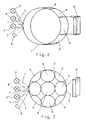
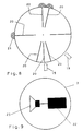
- 1A and 1B is a roll 1 lying horizontally trained, floating body shown. In the case 1A, it is in a guide 11 with a round cross section and in the case of FIG. 1B in a guide 10 with a rectangular one Cross section arranged.
- the drive of the horizontal Roller 1 can be either magnetic or by one the roll tangential grazing air flow are effected.
- the area of the roller 1 is a sensor device for detection an end position of the roller 1 is provided.
- This sensor device consists of three light sources 4, 4 'and 4' ' and a light sensor 5.
- the light source 4 sends red Light, the light source 4 'green light and the light source 4 '' blue light off.
- the generated by these light sources Light shines on an area on the surface of the roller 1 bundled, which is not larger than a colored field 6.
- the light reflected from this illuminated area falls on the light sensor 5.
- the light sources 4, 4 'and 4' ' turned on one after the other so that in the Light sensor only a significant intensity incident Light is detected when the color of the as the identification area trained colored field with the color of the light source matches.
- a similar arrangement is in FIG. 3 in the case of a free-floating ball Body shown. Because the reference numerals are identical are referred to the sensor process described above.
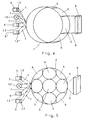
- a free-floating body shown in FIG. 4 which in turn is designed as a horizontally lying roller 1
- the sensor device has a polychrome Light source 12 whose light is on an area of the surface the roller 1 is bundled, which is not larger than one formed as a colored field on the surface of the roller Identifier area is. That reflected from this area Light falls on three light sensors 5, 5 'and 5' ', each of which optical filters 13, 13 'and 13' 'are connected upstream.
- the filter 13 leaves red light, the filter 13 'green Light and the filter 13 '' pass blue light.
- Is a Identification area marked for example as a red field see above the light source 12 bundles the field Beam of light reflected as red light from the field, being this light is passed through the filter 13 and onto the Sensor 5 hits while it is from filters 13 'and 13' ' is blocked so that the light sensors 5 'and 5' 'are not incident Register light.
- To this Way is a clear assignment of the color of a highlighted Field to one of the light sensors 5, 5 'and 5' ', and so it becomes a unique identification of the Identifier areas marked as colored fields.
- FIG. 5 relates to a similar embodiment of the invention as Fig. 4 with the difference that the free-floating Body is designed as a ball, on which as a colored Fields 6 marked identification areas are provided.
- the reference symbols are identical to those in FIG. 4 illustrated embodiment, so that in this regard to the is referred to there.
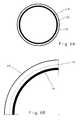
- FIG. 6A is a cross section through a floating body, either as a horizontal roller or as a single ball can be trained.
- FIG. 6B is an enlarged partial section of the in Fig. 6A shown body, this is either from a spherical or cylindrical base material 14, that with a printing foil provided with identification areas 15 is coated, for example colored fields or has predetermined optical identification symbols.
- On this Printing film 15 is transparent to visible light UV reflective tape arranged in different Areas has different densities.
- Such one free-floating body is preferably on its back illuminated with UV light, and the reflected light is from measured with a UV light sensor.
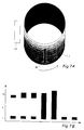
- the is again designed as a horizontally lying roller 1 an optical identification symbol 18 in on the outer surface Shape of a "1" provided.
- a CCD camera 17 is used for Detect the optical symbol 18 when it rotates the roller 1 moves past the camera 17.
- the one in this Fall received signals from the channels of the CCD camera shown in Fig. 7B, the abscissa of the time and their ordinate indicates the number of channels.
- the symbol 18 received first channels 1 and 9, then channels 1, 9 and 10, then all channels 1 to 10 and then all channels 1 to 11 inputs, which is followed by two inputs in channel 1.
- the identifier is stored digitally and serves as a comparison template for recognizing a pattern with the shape of the Symbols 18. This also enables pattern recognition perform on the back of the reel for the player is not visible and therefore cannot be manipulated. For in this case the player has a different identification area visible to the symbol 18 but locally in a fixed Relationship is related to the presence of this identifier area in the viewing window visible to the player can be concluded.
- floating bodies are a plurality, smaller, thinner Slots 20 are made in the surface of the ball 2, the is made of a metal. This makes the ball surrounding homogeneous magnetic field in a targeted manner, and interference fields 21 are formed.
- the interference fields 21 are detected by magnetic field sensors 19.
- To this end is a plurality of magnetic field sensors 19 around the body 2 arranged around. Due to the predetermined arrangement of the Slots 20 and the interference fields 21 generated thereby is in each magnetic field sensor 19 at a predetermined position of the Body 2 an empirically determinable intensity of the magnetic field measured.
- the values of each magnetic field sensor 19 measured local magnetic field intensity form a value scale, the predetermined for a certain position of the body 2 Indicates values.
- one is free floating body is a single ball 3 with an acoustic Signal generator 23 provided, the acoustic signals, i.e. Sound waves emitted in a predetermined direction. Because of corresponding sensors, not shown, which around these single ball 3 are arranged around and with appropriate The corresponding signal generator 13 is compared Receiving acoustic signals is a determination the spatial orientation or the end position of the ball 3 enables.
- Transponders 24 each issue predetermined identifiers, measured by a receiver 25 and then evaluated will. Due to the permanent installation of the transponder 24 along the surface of the roller 1 and the predetermined one Identification of each transponder by that of the Receiver 25 received identifier from the receiver 25 opposite Transponder 24 is the end position of the roller 1 upon receipt of a predetermined identifier and can therefore from an evaluation unit, not shown be evaluated. The same applies to that shown in FIG. 11 Single ball 3, the end position within the Viewing area 9 of the player is.
- the Identification of a transponder 24 of a plurality of transponders a clear assignment between a certain sphere 3 and their position with respect to the receiver 25.
- one is free floating body is a single ball 3 in a separating container 27 arranged, the visible to the player is.
- the ball 3 is predetermined Identifier area provided with a luminous excitable medium 26, which is excited by an exciter 29, so that it too begins to glow, and its glow is measured by a sensor becomes.
- a sensor 29 With different orientations of the identification area 26, with corresponding changes in the end position the ball 3 go hand in hand with changes in the Sensor 28 measured light intensity connected, so that too here empirically a relationship between the end position of the Ball 3 and the intensity measured with the sensor 28 can be.
- the different spatial orientations assigned intensity measurements are in a Evaluation unit, not shown, stored, each Measured value a certain spatial orientation of the ball 3 assigned. In this way, the end position of the ball 3 on the basis of an intensity value measured by the sensor 28 be determined.
Landscapes
- Physics & Mathematics (AREA)
- General Physics & Mathematics (AREA)
- Slot Machines And Peripheral Devices (AREA)
- Length Measuring Devices By Optical Means (AREA)
- Pinball Game Machines (AREA)
- Eye Examination Apparatus (AREA)
- Confectionery (AREA)
- Acyclic And Carbocyclic Compounds In Medicinal Compositions (AREA)
Description
- Fig. 1A und 1B
- mögliche Anordnungen für als horizontal liegende Walzen ausgebildete frei schwebende Körper in einem Spielautomaten;
- Fig. 2
- eine Ausführungsform des Spielautomaten, bei der die Kennungsbereiche von farbigen Lichtquellen be leuchtet werden;
- Fig. 3
- eine weitere Ausführungsform des Spielautomaten, bei der die Kennungsbereiche von farbigen Licht quellen beleuchtet werden;
- Fig. 4
- eine Ausführungsform des Spielautomaten, bei der die Kennungsbereiche jeweils unterschiedlich farbig markiert sind und das von ihnen reflektierte Licht von Fotosensoren ausgewertet wird, denen Farbfilter vorgeschaltet sind;
- Fig. 5
- eine weitere Ausführungsform des Spielautomaten ähnlich der in Fig. 4 gezeigten;
- Fig. 6A
- einen Querschnitt durch einen frei schwebenden Körper, der mit einer UV-Folie versehen ist;
- Fig. 6B
- einen vergrößerten Ausschnitt des in Fig. 6A gezeigten Querschnitts;
- Fig. 7A
- einen mit einem Kennungssymbol versehenen, frei schwebenden Körper gemäß der Erfindung;
- Fig. 7B
- die Empfangssignale einer CCD-Kamera bei Detektion des in Fig. 7A dargestellten Symbols;
- Fig. 8
- einen frei schwebenden Körper, dessen behandelte berfläche das den Körper umgebende Magnetfeld in vorherbestimmter Weise stört;
- Fig. 9
- einen frei schwebenden Körper, der mit einem aku stischen Signalgeber versehen ist;
- Fig. 10
- einen frei schwebenden Körper, der mit Transpondern versehen ist;
- Fig. 11
- einen weiteren frei schwebenden Körper, der mit ei nem Transponder versehen ist; und
- Fig. 12
- einen frei schwebenden Körper, der einen mit Hilfe einer strahlenden Substanz versehenen Kennungsbe reich aufweist.
Claims (10)
- Spielautomat mit mindestens einem in einem einsehbaren Spielfeld frei beweglichen Körper (1, 2, 3), dessen Oberfläche mit einer Kennung versehen ist, die zur Festlegung eines möglichen Spielgewinns vorgesehen ist, wobei der Körper (1, 2, 3) eine farbige Oberfläche (6) und/oder eine musterversehene Kennung aufweist und zumindest eine optische Abtasteinrichtung (17) mit einer den Körper beleuchtenden Lichtquelle (4, 12) und einer Sensoreinrichtung (5), die das vom Körper (1, 2, 3) reflektierte Licht mit festgelegter Wellenlänge erfaßt, vorgesehen ist, wobei der Körper mehrfarbig ist, mehrere Lichtquellen (4) zur Beleuchtung des Körpers (1, 2, 3) vorgesehen sind und das von der Sensoreinrichtung (5) erfaßte Licht zur Feststellung der Kennung verarbeitet wird, dadurch gekennzeichnet, daß die Lichtquellen (4) Licht verschiedener Wellenlängen aussenden und einzeln und/oder in ausgewählten Kombinationen eingeschaltet werden und jeder durch den Spieler einsehbaren Kennung eine zusätzliche Kennung zugeordnet ist, die sich auf einem nichteinsehbaren Bereich der Oberfläche des Körpers befindet, wobei diese Kennung aus UV-Licht reflektierendem Material besteht, und eine UV-Lichtquelle zur Beleuchtung des Körpers und ein Sensor zum Erfassen des reflektierten UV-Lichts vorgesehen sind.
- Spielautomat nach Anspruch 1, dadurch gekennzeichnet, daß als Kennungsträger eine UV-Reflektionsfolie (16) vorgesehen ist.
- Spielautomat nach einem der Ansprüche 1 oder 2, dadurch gekennzeichnet, daß unterschiedliche UV-Kennungsbereiche vorgesehen sind.
- Spielautomat nach einem der Ansprüche 1 bis 3, dadurch gekennzeichnet, daß Amplituden-Referenzwerte für die Kennungserfassung vorgesehen sind.
- Spielautomat nach einem der Ansprüche 1 bis 4, dadurch gekennzeichnet, daß eine polychrome Lichtquelle zur Beleuchtung des Körpers vorgesehen ist und drei Sensoren (5) mit jeweils vorgeschalteten, unterschiedlichen Farbfiltern (13) oder ein Sensor (5) mit drei schaltbaren Farbfiltern (13) zum Erfassen des reflektierten Lichts vorgesehen sind.
- Spielautomat nach einem der Ansprüche 1 bis 5, dadurch gekennzeichnet, daß als Kennung zwei Codestreifen mit Absolut- oder Inkrementalwertcodierung vorgesehen sind.
- Spielautomat nach einem der Ansprüche 1 bis 6, dadurch gekennzeichnet, daß als Sensor ein Fototransistor und/oder eine Fotodiode und/oder ein CCD-Array vorgesehen ist.
- Spielautomat nach einem der Ansprüche 1 bis 7, dadurch gekennzeichnet, daß als Kennung ein permanentes magnetisches, akustisches, elektromagnetisches (Transponder-) und/oder optisches (Fluoreszenz-) Feld vorgesehen ist, das der Körper aussendet, und daß als Sensor ein magnetischer, akustischer, Funk- und/oder optischer Sensor (28) vorgesehen ist.
- Spielautomat nach Anspruch 8, mit magnetischem Körper, dadurch gekennzeichnet, daß die Körperoberfläche Schlitze (20) als Kennungscodierung aufweist, die vom Sensor (19) erfaßt und in einer Auswerteeinrichtung die Kennung erfaßt wird, oder ein Referenzsensor vorgesehen ist, der das Magnetfeld ohne Schlitze erfaßt.
- Spielautomat nach Anspruch 8, dadurch gekennzeichnet, daß der Körper mit einer strahlenden Flüssigkeit (26) als Kennungssubstanz gefüllt ist.
Applications Claiming Priority (3)
| Application Number | Priority Date | Filing Date | Title |
|---|---|---|---|
| DE19500458 | 1995-01-10 | ||
| DE19500458A DE19500458A1 (de) | 1995-01-10 | 1995-01-10 | Spielautomat |
| PCT/DE1996/000038 WO1996021914A1 (de) | 1995-01-10 | 1996-01-05 | Spielautomat |
Publications (2)
| Publication Number | Publication Date |
|---|---|
| EP0803112A1 EP0803112A1 (de) | 1997-10-29 |
| EP0803112B1 true EP0803112B1 (de) | 1998-09-02 |
Family
ID=7751189
Family Applications (1)
| Application Number | Title | Priority Date | Filing Date |
|---|---|---|---|
| EP96900509A Expired - Lifetime EP0803112B1 (de) | 1995-01-10 | 1996-01-05 | Spielautomat |
Country Status (5)
| Country | Link |
|---|---|
| EP (1) | EP0803112B1 (de) |
| AT (1) | ATE170650T1 (de) |
| DE (2) | DE19500458A1 (de) |
| ES (1) | ES2123333T3 (de) |
| WO (1) | WO1996021914A1 (de) |
Families Citing this family (1)
| Publication number | Priority date | Publication date | Assignee | Title |
|---|---|---|---|---|
| US7867092B2 (en) | 2002-04-08 | 2011-01-11 | Igt | Gaming apparatus with an optical wireless system |
Family Cites Families (6)
| Publication number | Priority date | Publication date | Assignee | Title |
|---|---|---|---|---|
| GB1180560A (en) * | 1966-10-23 | 1970-02-04 | Mayfield Electronics Ltd | Improvements in or relating to apparatus for Throwing Dice |
| DE2921159A1 (de) * | 1979-05-25 | 1980-12-04 | Paul Gauselmann | Anordnung fuer einen geldspielautomaten |
| CA1213623A (en) * | 1982-12-10 | 1986-11-04 | Steven L. Foley | Gaming apparatus |
| DE3836455C2 (de) * | 1987-05-25 | 1993-10-21 | Norbert Dresselhaus | Spielautomat |
| US5088737A (en) * | 1990-09-12 | 1992-02-18 | Alan Frank | Player operable lottery machine with system for automatically identifying spheres |
| GB9305341D0 (en) * | 1993-03-16 | 1993-05-05 | Maygay Machines | Game devices and machines |
-
1995
- 1995-01-10 DE DE19500458A patent/DE19500458A1/de not_active Withdrawn
-
1996
- 1996-01-05 WO PCT/DE1996/000038 patent/WO1996021914A1/de not_active Ceased
- 1996-01-05 EP EP96900509A patent/EP0803112B1/de not_active Expired - Lifetime
- 1996-01-05 DE DE59600511T patent/DE59600511D1/de not_active Expired - Fee Related
- 1996-01-05 AT AT96900509T patent/ATE170650T1/de not_active IP Right Cessation
- 1996-01-05 ES ES96900509T patent/ES2123333T3/es not_active Expired - Lifetime
Also Published As
| Publication number | Publication date |
|---|---|
| EP0803112A1 (de) | 1997-10-29 |
| ES2123333T3 (es) | 1999-01-01 |
| WO1996021914A1 (de) | 1996-07-18 |
| ATE170650T1 (de) | 1998-09-15 |
| DE59600511D1 (de) | 1998-10-08 |
| DE19500458A1 (de) | 1996-07-11 |
Similar Documents
| Publication | Publication Date | Title |
|---|---|---|
| EP0696236B1 (de) | Verfahren und vorrichtung zur sortierung von materialteilen | |
| DE69806325T2 (de) | Winkelsensor der eine multi-pixel optische Vorrichtung verwendet | |
| DE3784142T2 (de) | Pruefung eines artikels. | |
| DE69223056T2 (de) | Sortieren von auf unterschiedliche weise identifizierten artikeln | |
| DE2624308C2 (de) | Einrichtung zum Abtasten von Glasflaschen zwecks Formerkennung | |
| EP1268935B1 (de) | Sicherheitspapier mit aufgebrachter codierung aus lumineszierenden melierfasern und verfahren zur maschinellen überprüfung dieser codierung | |
| DE60130546T2 (de) | Optimale symbologiebeleuchtungsvorrichtung und -verfahren | |
| DE102009039254A1 (de) | Vorrichtung und Verfahren zum Inspizieren etikettierter Gefäße | |
| EP1154225B1 (de) | Erfassen der Randkante, Markierung einer laufenden Warenbahn mit zweiter diffuser Lichtquelle sowie Lichtzeiger | |
| DE2157797A1 (de) | Artikelsortierverfahren und geraet zur ausfuehrung des verfahrens | |
| DE2829778A1 (de) | Wertzeichen, wie kredit- oder ausweiskarte und geraet zum pruefen des wertzeichens bzw. der karte | |
| DE3507569A1 (de) | Vorrichtung zur erfassung von kennzeichnungen auf sich bewegenden kennzeichnungstraegern | |
| EP0952082A2 (de) | Vorrichtung zum Prüfen von Einheiten aus mehreren Einzelgegenständen, Materiallagen oder dergleichen | |
| DE19607258A1 (de) | Verfahren und Vorrichtung zur Detektion und/oder zur Größen- und/oder Lagebestimmung eines Objekts | |
| EP0803112B1 (de) | Spielautomat | |
| DE1524687B2 (de) | Geraet zum ueberpruefen der echtheit von wertpapieren | |
| DE69511159T2 (de) | Abtastvorrichtung | |
| DE3203851C2 (de) | ||
| DE2713396A1 (de) | Verfahren und vorrichtung zur kennzeichnung oder identifizierung eines leuchtmaterial enthaltenden oder tragenden koerpers | |
| WO2003085608A2 (de) | Vorrichtung zur verifikation von sicherheitsmerkmalen | |
| DE60038184T2 (de) | Verfahren zur bestimmung eines merkmals eines sicherheitsdokuments, wie z.b. eine banknote | |
| EP0325558A1 (de) | Verfahren und Vorrichtung zum Feststellen von Fremdkörpern in einem Strom von für elektromagnetische Strahlung durchlässigen Körpern | |
| EP0884409B1 (de) | Vorrichtung zur Erfassung von Parametern eines langgestreckten Prüfguts | |
| DE3900056A1 (de) | Identifizierungsvorrichtung mit optisch lesbaren etiketten und hierfuer geeignete etiketten | |
| DE3736407C2 (de) |
Legal Events
| Date | Code | Title | Description |
|---|---|---|---|
| PUAI | Public reference made under article 153(3) epc to a published international application that has entered the european phase |
Free format text: ORIGINAL CODE: 0009012 |
|
| 17P | Request for examination filed |
Effective date: 19970705 |
|
| AK | Designated contracting states |
Kind code of ref document: A1 Designated state(s): AT DE ES GB GR IT NL |
|
| GRAG | Despatch of communication of intention to grant |
Free format text: ORIGINAL CODE: EPIDOS AGRA |
|
| 17Q | First examination report despatched |
Effective date: 19971126 |
|
| GRAG | Despatch of communication of intention to grant |
Free format text: ORIGINAL CODE: EPIDOS AGRA |
|
| GRAH | Despatch of communication of intention to grant a patent |
Free format text: ORIGINAL CODE: EPIDOS IGRA |
|
| GRAH | Despatch of communication of intention to grant a patent |
Free format text: ORIGINAL CODE: EPIDOS IGRA |
|
| GRAA | (expected) grant |
Free format text: ORIGINAL CODE: 0009210 |
|
| AK | Designated contracting states |
Kind code of ref document: B1 Designated state(s): AT DE ES GB GR IT NL |
|
| PG25 | Lapsed in a contracting state [announced via postgrant information from national office to epo] |
Ref country code: NL Free format text: LAPSE BECAUSE OF FAILURE TO SUBMIT A TRANSLATION OF THE DESCRIPTION OR TO PAY THE FEE WITHIN THE PRESCRIBED TIME-LIMIT Effective date: 19980902 Ref country code: IT Free format text: LAPSE BECAUSE OF FAILURE TO SUBMIT A TRANSLATION OF THE DESCRIPTION OR TO PAY THE FEE WITHIN THE PRE;WARNING: LAPSES OF ITALIAN PATENTS WITH EFFECTIVE DATE BEFORE 2007 MAY HAVE OCCURRED AT ANY TIME BEFORE 2007. THE CORRECT EFFECTIVE DATE MAY BE DIFFERENT FROM THE ONE RECORDED.SCRIBED TIME-LIMIT Effective date: 19980902 Ref country code: GR Free format text: LAPSE BECAUSE OF NON-PAYMENT OF DUE FEES Effective date: 19980902 |
|
| REF | Corresponds to: |
Ref document number: 170650 Country of ref document: AT Date of ref document: 19980915 Kind code of ref document: T |
|
| REF | Corresponds to: |
Ref document number: 59600511 Country of ref document: DE Date of ref document: 19981008 |
|
| GBT | Gb: translation of ep patent filed (gb section 77(6)(a)/1977) |
Effective date: 19981124 |
|
| REG | Reference to a national code |
Ref country code: ES Ref legal event code: FG2A Ref document number: 2123333 Country of ref document: ES Kind code of ref document: T3 |
|
| PGFP | Annual fee paid to national office [announced via postgrant information from national office to epo] |
Ref country code: AT Payment date: 19990122 Year of fee payment: 4 |
|
| PGFP | Annual fee paid to national office [announced via postgrant information from national office to epo] |
Ref country code: ES Payment date: 19990127 Year of fee payment: 4 |
|
| NLV1 | Nl: lapsed or annulled due to failure to fulfill the requirements of art. 29p and 29m of the patents act | ||
| PGFP | Annual fee paid to national office [announced via postgrant information from national office to epo] |
Ref country code: DE Payment date: 19990213 Year of fee payment: 4 |
|
| PLBE | No opposition filed within time limit |
Free format text: ORIGINAL CODE: 0009261 |
|
| STAA | Information on the status of an ep patent application or granted ep patent |
Free format text: STATUS: NO OPPOSITION FILED WITHIN TIME LIMIT |
|
| 26N | No opposition filed | ||
| PG25 | Lapsed in a contracting state [announced via postgrant information from national office to epo] |
Ref country code: GB Free format text: LAPSE BECAUSE OF NON-PAYMENT OF DUE FEES Effective date: 20000105 Ref country code: AT Free format text: LAPSE BECAUSE OF NON-PAYMENT OF DUE FEES Effective date: 20000105 |
|
| PG25 | Lapsed in a contracting state [announced via postgrant information from national office to epo] |
Ref country code: ES Free format text: LAPSE BECAUSE OF NON-PAYMENT OF DUE FEES Effective date: 20000107 |
|
| GBPC | Gb: european patent ceased through non-payment of renewal fee |
Effective date: 20000105 |
|
| PG25 | Lapsed in a contracting state [announced via postgrant information from national office to epo] |
Ref country code: DE Free format text: LAPSE BECAUSE OF NON-PAYMENT OF DUE FEES Effective date: 20001101 |
|
| REG | Reference to a national code |
Ref country code: ES Ref legal event code: FD2A Effective date: 20010910 |