EP0803029B1 - Selbsteinstellendes lager für hochtemperaturanwendungen - Google Patents
Selbsteinstellendes lager für hochtemperaturanwendungen Download PDFInfo
- Publication number
- EP0803029B1 EP0803029B1 EP95930839A EP95930839A EP0803029B1 EP 0803029 B1 EP0803029 B1 EP 0803029B1 EP 95930839 A EP95930839 A EP 95930839A EP 95930839 A EP95930839 A EP 95930839A EP 0803029 B1 EP0803029 B1 EP 0803029B1
- Authority
- EP
- European Patent Office
- Prior art keywords
- bearing
- roll
- shaft means
- annular
- sleeve
- Prior art date
- Legal status (The legal status is an assumption and is not a legal conclusion. Google has not performed a legal analysis and makes no representation as to the accuracy of the status listed.)
- Expired - Lifetime
Links
Images

Classifications
-
- F—MECHANICAL ENGINEERING; LIGHTING; HEATING; WEAPONS; BLASTING
- F16—ENGINEERING ELEMENTS AND UNITS; GENERAL MEASURES FOR PRODUCING AND MAINTAINING EFFECTIVE FUNCTIONING OF MACHINES OR INSTALLATIONS; THERMAL INSULATION IN GENERAL
- F16C—SHAFTS; FLEXIBLE SHAFTS; ELEMENTS OR CRANKSHAFT MECHANISMS; ROTARY BODIES OTHER THAN GEARING ELEMENTS; BEARINGS
- F16C33/00—Parts of bearings; Special methods for making bearings or parts thereof
- F16C33/02—Parts of sliding-contact bearings
- F16C33/04—Brasses; Bushes; Linings
- F16C33/16—Sliding surface consisting mainly of graphite
-
- B—PERFORMING OPERATIONS; TRANSPORTING
- B21—MECHANICAL METAL-WORKING WITHOUT ESSENTIALLY REMOVING MATERIAL; PUNCHING METAL
- B21B—ROLLING OF METAL
- B21B39/00—Arrangements for moving, supporting, or positioning work, or controlling its movement, combined with or arranged in, or specially adapted for use in connection with, metal-rolling mills
- B21B39/008—Rollers for roller conveyors
-
- F—MECHANICAL ENGINEERING; LIGHTING; HEATING; WEAPONS; BLASTING
- F16—ENGINEERING ELEMENTS AND UNITS; GENERAL MEASURES FOR PRODUCING AND MAINTAINING EFFECTIVE FUNCTIONING OF MACHINES OR INSTALLATIONS; THERMAL INSULATION IN GENERAL
- F16C—SHAFTS; FLEXIBLE SHAFTS; ELEMENTS OR CRANKSHAFT MECHANISMS; ROTARY BODIES OTHER THAN GEARING ELEMENTS; BEARINGS
- F16C23/00—Bearings for exclusively rotary movement adjustable for aligning or positioning
- F16C23/02—Sliding-contact bearings
- F16C23/04—Sliding-contact bearings self-adjusting
- F16C23/043—Sliding-contact bearings self-adjusting with spherical surfaces, e.g. spherical plain bearings
- F16C23/045—Sliding-contact bearings self-adjusting with spherical surfaces, e.g. spherical plain bearings for radial load mainly, e.g. radial spherical plain bearings
- F16C23/046—Sliding-contact bearings self-adjusting with spherical surfaces, e.g. spherical plain bearings for radial load mainly, e.g. radial spherical plain bearings with split outer rings
-
- B—PERFORMING OPERATIONS; TRANSPORTING
- B21—MECHANICAL METAL-WORKING WITHOUT ESSENTIALLY REMOVING MATERIAL; PUNCHING METAL
- B21B—ROLLING OF METAL
- B21B31/00—Rolling stand structures; Mounting, adjusting, or interchanging rolls, roll mountings, or stand frames
- B21B31/07—Adaptation of roll neck bearings
-
- F—MECHANICAL ENGINEERING; LIGHTING; HEATING; WEAPONS; BLASTING
- F16—ENGINEERING ELEMENTS AND UNITS; GENERAL MEASURES FOR PRODUCING AND MAINTAINING EFFECTIVE FUNCTIONING OF MACHINES OR INSTALLATIONS; THERMAL INSULATION IN GENERAL
- F16C—SHAFTS; FLEXIBLE SHAFTS; ELEMENTS OR CRANKSHAFT MECHANISMS; ROTARY BODIES OTHER THAN GEARING ELEMENTS; BEARINGS
- F16C2322/00—Apparatus used in shaping articles
- F16C2322/12—Rolling apparatus, e.g. rolling stands, rolls
Definitions
- This invention is related to bearing means for high temperature applications, and more particularly to a bearing useful for supporting a steel mill roll transferring a hot steel strip.
- Rolls are used in steel mills for transferring hot strips of steel in an environment where the strip may be 1800° F. to 2200° (980°C to 1200°C) or more.
- the roll and the supporting bearings become very hot.
- the temperature varies substantially as the furnace is opened and closed.
- Roller bearings are commonly used for such applications. Each bearing supports a short shaft that extends from each end of the roll.
- Roller bearings have a relatively limited life for several reasons.
- One reason is that the rollers in the bearing are mounted between an inner race and an outer race. Since the diameter of the inner race is less than the diameter of the outer race, the rollers must slide in one direction on the inner race or in the opposite direction on the outer race. The sliding develops facets in the races, requiring the rollers to jump over each facet, and causing the rolls to vibrate. This is sometimes referred to as "skidding wear”.
- rollers formed of a hard steel tend to corrode because of the high operating temperature.
- Other materials, such as stainless steel are too soft and tend to gall.
- the steel strip load tends to flex the roll.
- the flexing roll causes each end shaft to shift slightly in its bearing. Rotter bearings have a low tolerance for such shifting. Flexing also occurs when the roll returns to its original shape as it is unloaded. This is a vertical flexing. In some cases, a horizontal flexing occurs because some of the rolls may be rotating slower than others. A steel strip pushing a slower roll forward, causes a forward horizontal flexing. A reverse horizontal flexing takes place when the roll velocity is higher than the strip velocity.
- SU 179 724 A discloses a convex spherical bearing element which engages the internal side of a frusto conical bearing surface in order to self-align a roll with respect to the bearing.
- the roll or the neck is not anchored axially and freely slides in relation to the bearing.
- Document JP 5 187 445 A discloses a self-aligning rolling bearing with a plurality of rolling elements.
- the rolling bearing is used in a hot dip zinc bath.
- Document JP 01 159 359 A describes a bearing supporting device for dipping roll of hot dip coating bath. Both ends of a roll are supported by rolling bearings made of ceramics. A self-aligning mechanism is preferably added between the bearings as well as the supporting members and the retaining member. The rolling bearings are thereby stably supported without exerting excessive load thereto and without losing their self-alignment property.
- Document JP 61 084 413 A describes a radial bearing.
- a sleeve has an outer convex spherical shape and cooperates with a ceramic bearing forming a concave spherical surface.
- the ceramic bearing is divided into two parts, so that a partial hit of the bearing can be prevented.
- Document FR 1 583 685 A describes the use of a self-aligning ball bearing for driving a water screw.
- the bearing has a partially spherical surface and a partially concave surface.
- Document FR 541 155 A describes the use of a bearing for supporting a shaft e.g. in a rolling mill, wherein the bearing has convex and concave spherical surfaces, i.e. a combination having the features of the preamble of claim1.
- the broad purpose of the present invention is to provide an improved combination steel mill roll and bearing, and a self-aligning bearing useful for high temperature rolls, that does not require lubrication, will accommodate roll flexing, and is effective at high temperatures such as 1000° F 540°C.
- a preferred embodiment of the invention comprises a bearing housing having an opening larger than the diameter of the roll shaft.
- a pair of axially-spaced rings are mounted in the housing. Each ring has a concave, partially spherical bearing surface.
- the bronze sleeve is shrink-fitted over a graphite sleeve, forming a unitary structure.
- the graphite sleeve is formed of a high temperature extremely hard graphite material, and is slidably mounted on the roll shaft.
- the composite sleeve provides a large bearing surface as the shaft is rotating, and accommodates a swinging motion of the shaft as the roller flexes under the load of a moving strip.
- the shaft is of a relatively soft steel.
- a hard steel sleeve is mounted over the shaft which in turn slidably engages the graphite sleeve.
- the invention is also useful in applications where the bearing may be immersed in a zinc or aluminum bath.
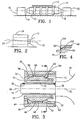
- an annealing roll 10 for transferring a steel strip 12 from an annealing furnace has a pair of shaft ends 14 and 16 rotatably mounted in self-aligning bearing means 18 and 20, respectively.
- Roll 10 may be of the type illustrated in my U.S. Patent No. 5,338,280 issued August 16, 1994 for "Annealing and Tunnel Furnace Rolls".
- Bearings 18 and 20 are identical except for a right and left hand relationship.
- Bearing 18 is illustrated in Figure 3 and comprises a steel housing 30 having an opening 32 for receiving shaft 14 of roll 10.
- Shaft 14 is made of a relatively soft stainless steel, because it cannot be brittle.
- a steel sleeve 34 is mounted over shaft 14 and held in place by set screw means 36 and 38. The set screws are fastened into recessed openings in the sleeve to engage the shaft. Thus, sleeve 34 rotates with the shaft.
- a pair of heat treated steel (R c 50/60) bearing rings 40 and 42 are mounted in the bearing opening.
- the bearing opening has an internal shoulder 44, which extends radially inwardly from an internal cylindrical surface 46.
- Bearing ring 40 is seated against shoulder 4.4. Both rings are mounted in sliding contact with cylindrical surface 46.
- a cylindrical centering sleeve 48 is mounted between ring 40 and ring 42.
- An annular nut 50 is threadably mounted at 52 at the right end of the bearing opening as viewed in Figure 3 . The nut is tightened to urge ring 42, sleeve 48 and ring 40 toward shoulder 44 to align their bearing surfaces and to prevent their rotation in the housing.
- An annular bronze retainer 54 is mounted in the bearing opening and has a convex, partially spherical annular bearing surface 56, slidably engaging a partially spherical annular concave slidable bearing surface 58 of bearing ring 40.
- the retainer has an intermediate cylindrical section 60 with a diameter slightly less than the internal diameter of the centering sleeve.
- the retainer has a second partially spherical annular convex bearing surface 62 slidably engaging a concave annular partially spherical bearing surface 64 on the inside of bearing ring 42.
- the retainer can be swung laterally with respect to the fixed axis 24 of the bearing.
- a graphite sleeve 70 is attached to retainer 54, preferably by having the retainer shrink-fitted around the sleeve.
- the sleeve has an inner cylindrical surface 72 rotatably slidably engaging the outer cylindrical surface of sleeve 34.
- Graphite sleeve 70 has good operating characteristics up to 1500° F (820°C ). It is formed of an extruded, compressed dense graphite formed in a pyrolitic process, or of carbon/graphite in a mechanical process.
- the axis 22 of the roll is shown in Figure 3 as aligned with axis 66 of the bearing, however, the internal bearing components will slidably shift with the roll shaft as the roll flexes. Consequently, the axis of the shaft is always aligned with the axis of the sliding components of the bearing, that is, graphite sleeve 70 and bearing rings 42 and 44.
- the bearing is effective at high steel-mill temperatures and does not require lubrication. It has a substantially greater life than roller bearings because the shaft has a substantial bearing surface slidably engaging the graphite sleeve in all flexed positions of the shaft.
- Figure 4 illustrates an alternative bearing ring 100 which is identical to ring 40, except that it has an internal concave frusto-conical annular bearing surface 102 instead of the internal spherical surface 58 of ring 40.
- the companion bearing ring can also have a frusto-conical concave surface engaging the opposite end of the retainer.
- Figure 6 illustrates another self-aligning bearing in which bearing 200 is supported by a hanger 201 having an internal cylindrical opening 202.
- This application is useful for an environment in which roll 204 and the bearing are immersed in a metal bath 204A, such as aluminum, if appropriate material changes are made to prevent molten metal corrosion attack.
- a sleeve 206 made from cast iron, 52100 steel or stainless steel is seated against an annular shoulder 207 inside a cylindrical opening 202.
- Sleeve 206 has an annular shoulder 208, a frusto-conical concave annular bearing shoulder 210 and a cylindrical surface 212.
- An annular retainer 214 also made from Stellite or 316L stainless steel, has a cylindrical inner surface 216 shrink-fitted over ceramic sleeve 218.
- Sleeve 218 can also be made of cast iron or 52100 steel.
- Retainer 214 has a partially spherical annular convex shoulder 220 slidably engaging bearing surface 210.
- the opposite end of the retainer has a partially spherical annular convex surface 222 slidably engaging an annular concave frusto-conical surface 224 of a bearing ring 226.
- Bearing ring 226 is spaced from shoulder 210 and preferably is retained in the bearing opening by a retainer ring 228 which is welded at 229 to hanger 201.
- the inner surface 230 of sleeve 218 slidably engages the rotating shaft 232 of roll 204.
- retainer 214 and sleeve 218 are movable together as a composite bearing component, with the sleeve providing a low-friction sliding surface for the shaft, while the convex spherical surfaces of the retainer provide a self-aligning sliding fit with respect to sleeve 206.
- the bearing accommodates both the rotating load of the shaft as well as the flexing load of the steel strip as the shaft swings up and down in the direction of arrows 234.
- the opposite end of the roll has a similar bearing so that the roll is suspended between two self-aligning bearings.
Landscapes
- Engineering & Computer Science (AREA)
- General Engineering & Computer Science (AREA)
- Mechanical Engineering (AREA)
- Support Of The Bearing (AREA)
- Rolls And Other Rotary Bodies (AREA)
- Compositions Of Oxide Ceramics (AREA)
- Magnetic Bearings And Hydrostatic Bearings (AREA)
- Sliding-Contact Bearings (AREA)
- Physical Vapour Deposition (AREA)
Claims (5)
- Kombination aus Walze und Lager, die zum Befördern eines erwärmten Stahlstreifens (12) von einer ersten Position in eine zweite Position geeignet ist, umfassend:eine Walze (10) mit einer Länge, die dazu geeignet, einen Stahlstreifen (12) zu tragen, wenn die Walze (10) um eine erste Drehachse (22) gedreht wird, wobei die Walze ein erstes Ende und ein zweites Ende hat,erste Wellenmittel (14), die ein lagergestütztes Ende haben, das sich axial von dem ersten Ende der Walze (10) erstreckt und daran befestigt ist, und zweite Wellenmittel (16), die ein lagergestütztes Ende haben, das sich axial von dem zweiten Ende der Rolle (10) erstreckt und daran befestigt ist, wobei die beiden Wellenmittel eine Drehachse (22) haben,selbsteinstellende Lagermittel (18, 20), die jede der Wellenmittel (14, 16) tragen, wobei jede der Lagermittel umfassen:dadurch gekennzeichnet, dass die erste Lagerstruktur eine Graphithülse (70) umfasst, die dazu geeignet ist, die Wellenmittel (14, 16) drehbar mit ihrer zylindrischen Innenfläche (72) zu stützen, und ein Rückhalteelement (54), das die zum Teil sphärische Lageraußenfläche (56, 62) umfasst,ein Gehäuse (30),eine erste ringförmige Lagerstruktur, die beweglich in dem Gehäuse gelagert ist und eine zylindrische Innenfläche (72) aus einem Material niedriger Reibung hat, die verschiebbar an den Wellenmitteln (14, 16) gelagert ist, und eine Außenfläche, die eine ringförmige, zum Teil sphärische Lagerfläche (56, 62) hat, die um das lagergestützte Ende der dazugehörigen Wellenmittel (14, 16) angeordnet ist, undeine zweite ringförmige Lagerstruktur (40, 42, 48), die fest in dem Gehäuse (30) angebracht ist und eine ortsfeste Lagerachse (24) hat, und die verschiebbar mit der ringförmigen, zum Teil sphärischen Oberfläche (56, 62) der ersten Lagerstruktur in Eingriff steht, um zu ermöglichen, dass sich die Wellenmittel (14, 16) in der zweiten Lagerstruktur (40, 42, 48) drehen, wenn die Wellenmittel (14, 16) in einem spitzen Winkel in Bezug auf die ortsfeste Achse der zweiten Lagerstruktur (40, 42, 48) schwingen,
wobei die Graphithülse (70) an dem Rückhalteelement (54) angebracht ist, indem das Rückhalteelement (54) um die Graphithülse (70) aufgeschrumpft wurde. - Kombination aus Walze und Lager nach Anspruch 1, in der jede der Wellenmittel (14, 16) eine entfernbar an dem lagergestützten Ende der Wellenmittel angebrachte Hülse (34) aus einer Stahllegierung umfassen, um sich damit drehen zu können, wobei die Hülse (34) eine zylindrische äußere Lagerfläche hat, die verschiebbar und drehbar in der Graphithülse (70) der ersten Lagerstruktur angebracht ist.
- Kombination nach Anspruch 1, in der das Gehäuse (30) eine interne ringförmige Schulter (44) hat, wobei die zweite Lagerstruktur ein Paar zueinander beabstandeter Lagerringe (40, 42) umfasst, die in dem Gehäuse (30) angeordnet sind, wobei jeder der Ringe (40, 42) eine ringförmige konkave Lagerfläche (58, 64) hat, die verschiebbar mit der ersten Lagerstruktur in Eingriff steht, wobei einer (40) des Paars von Ringen in Anlage an die Schulter (44) angeordnet ist, wobei ein ringförmiges Zentrierrückhalteelement (48) zwischen den Ringen (40, 42) angeordnet ist, und eine Mutter (50) in die Gehäuseöffnung geschraubt ist, um das Paar zueinander beabstandeter Lagerringe (40, 42) und das Rückhalteelement (48) axial in Richtung der Schulter (44) zu drücken.
- Kombination nach Anspruch 3, bei der jeder des Paares von Lagerringen (40, 42) eine konkave, zum Teil sphärische Lagerfläche (58, 64) hat, die mit der ersten Lagerstruktur verschiebbar in Eingriff steht.
- Kombination nach Anspruch 1, in der die Wellenmittel der Walze ermöglichen, seitwärts in Bezug auf die Achse der zweiten Lagerstruktur zu schwingen.
Applications Claiming Priority (3)
| Application Number | Priority Date | Filing Date | Title |
|---|---|---|---|
| US370311 | 1995-01-09 | ||
| US08/370,311 US5549393A (en) | 1995-01-09 | 1995-01-09 | Self-aligning bearing for high temperature applications |
| PCT/US1995/010428 WO1996021809A1 (en) | 1995-01-09 | 1995-08-17 | Self-aligning bearing for high temperature applications |
Publications (4)
| Publication Number | Publication Date |
|---|---|
| EP0803029A1 EP0803029A1 (de) | 1997-10-29 |
| EP0803029A4 EP0803029A4 (de) | 1999-02-10 |
| EP0803029B1 true EP0803029B1 (de) | 2008-02-20 |
| EP0803029B8 EP0803029B8 (de) | 2008-06-25 |
Family
ID=23459105
Family Applications (1)
| Application Number | Title | Priority Date | Filing Date |
|---|---|---|---|
| EP95930839A Expired - Lifetime EP0803029B8 (de) | 1995-01-09 | 1995-08-17 | Selbsteinstellendes lager für hochtemperaturanwendungen |
Country Status (8)
| Country | Link |
|---|---|
| US (2) | US5549393A (de) |
| EP (1) | EP0803029B8 (de) |
| JP (1) | JPH10512655A (de) |
| AT (1) | ATE386890T1 (de) |
| AU (1) | AU3407295A (de) |
| CA (1) | CA2208064C (de) |
| DE (1) | DE69535715T2 (de) |
| WO (1) | WO1996021809A1 (de) |
Families Citing this family (34)
| Publication number | Priority date | Publication date | Assignee | Title |
|---|---|---|---|---|
| DE19911212A1 (de) * | 1999-03-12 | 2000-09-14 | Mann & Hummel Filter | Wellenlagerung mit Lagerkalotte |
| US6004037A (en) * | 1998-06-04 | 1999-12-21 | Rexnord Corporation | Bearing assembly with spherical bearing surfaces |
| JP2001193735A (ja) * | 2000-01-05 | 2001-07-17 | Minebea Co Ltd | 球面滑り軸受のトルク調節機構 |
| JP2001193734A (ja) * | 2000-01-05 | 2001-07-17 | Minebea Co Ltd | 球面滑り軸受の固定方法 |
| US7108331B2 (en) * | 2000-02-28 | 2006-09-19 | Myron Stuart Hurwitz | Generation of in-line skates and skate-boards with safety “EDGING FRICTION CONTROL™” |
| JP2001295756A (ja) * | 2000-04-11 | 2001-10-26 | Toyota Industries Corp | 圧縮機 |
| US6692689B2 (en) * | 2001-12-14 | 2004-02-17 | Jorge A. Morando | Sink roll assembly with forced hydrodynamic film lubricated bearings and self-aligning holding arms |
| US6719945B2 (en) | 2001-12-14 | 2004-04-13 | Jorge A. Morando | Galvanizing roll assembly with self-aligning hydrodynamic film lubricated roller-bearings |
| EP1431595A3 (de) * | 2002-12-16 | 2004-12-22 | ZF Lemförder Metallwaren AG | Kugelgelenk |
| ITRM20030447A1 (it) | 2003-09-30 | 2005-04-01 | Danieli Off Mecc | Dispositivo di supporto per rulli. |
| US7128061B2 (en) * | 2003-10-31 | 2006-10-31 | Vortech Engineering, Inc. | Supercharger |
| US7815373B2 (en) * | 2004-04-19 | 2010-10-19 | InsituTec Inc. | Symmetric spindle design |
| EP1781951B1 (de) | 2004-07-01 | 2014-05-21 | Elliott Company | Rotorsystem mit vier lagern |
| EP1617093A1 (de) * | 2004-07-16 | 2006-01-18 | Ab Skf | Lager aus Leichtmetall und keramisches Material |
| US7293920B2 (en) * | 2005-03-14 | 2007-11-13 | Northrop Grumman Corporation | Self-aligning bearing assembly capable of reacting radial and axial loads |
| US7783072B2 (en) * | 2005-04-27 | 2010-08-24 | Therapeias Health Management, Llc | Methods and systems for clinical trial data management |
| JP4550732B2 (ja) | 2005-12-20 | 2010-09-22 | 株式会社椿本チエイン | 固体潤滑無給油チェーン |
| KR100711444B1 (ko) * | 2005-12-23 | 2007-04-24 | 주식회사 포스코 | 도금조 롤의 축수부장치 |
| US20070230844A1 (en) * | 2006-04-04 | 2007-10-04 | Jeremy King | Combination cylindrical and spherical joint |
| DE502008001907D1 (de) * | 2008-09-01 | 2011-01-05 | Band Zink Gmbh | Führungsrollen-Drehlagerung für ein Metallschmelzbad |
| US9238973B2 (en) * | 2009-12-29 | 2016-01-19 | Rolls-Royce Corporation | Gas turbine engine and foil bearing system |
| US9674807B2 (en) | 2010-06-11 | 2017-06-06 | Clearwire IP Holdings, LLC | Subcarrier signal for synchronization in macro network |
| US8451814B2 (en) | 2010-06-11 | 2013-05-28 | Clearwire Ip Holdings Llc | Carrier signals for synchronization |
| US9844014B2 (en) | 2010-06-11 | 2017-12-12 | Sprint Spectrum L.P. | Alternatives to satellite signals for synchronization in macro network |
| DE102010042074B3 (de) * | 2010-10-06 | 2012-02-09 | Aktiebolaget Skf | Lagergehäuse und Lageranordnung |
| US8500333B2 (en) * | 2011-05-24 | 2013-08-06 | Siemens Industry, Inc. | Self aligning oil film bearing |
| US9885386B2 (en) * | 2015-06-15 | 2018-02-06 | General Electric Company | Bearing assembly |
| US9951810B2 (en) * | 2016-01-20 | 2018-04-24 | Summit Esp, Llc | Electrical submersible motor radial support bearing |
| US10294988B2 (en) | 2016-07-14 | 2019-05-21 | Cnh Industrial America Llc | Pillow block bearing assembly for a drivetrain assembly of a work vehicle |
| CN107061485A (zh) * | 2017-02-24 | 2017-08-18 | 上海凯波水下工程有限公司 | 一种用于海底电缆敷设船上的电缆转盘底部的滚子支承 |
| DE102020205250B4 (de) * | 2020-04-24 | 2021-11-11 | Kocks Technik Gmbh & Co Kg | Führungsvorrichtung für Langprodukte |
| CN112377532B (zh) * | 2020-11-26 | 2024-11-08 | 中铁十八局集团泵业有限公司 | 一种运输用保护轴承的铜套 |
| EP4092282A1 (de) * | 2021-05-18 | 2022-11-23 | Microtecnica S.r.l. | Lageranordnung |
| US12504030B2 (en) * | 2021-12-14 | 2025-12-23 | Atlas Machine And Supply, Inc. | System for securing objects having different coefficients of thermal expansion |
Family Cites Families (14)
| Publication number | Priority date | Publication date | Assignee | Title |
|---|---|---|---|---|
| FR541155A (fr) * | 1920-10-11 | 1922-07-24 | Palier à rotule | |
| GB558442A (en) * | 1942-07-02 | 1944-01-05 | Richard Edgar Holbrook | Improvements in or relating to thrust bearings |
| US2627443A (en) * | 1950-02-10 | 1953-02-03 | Gen Electric | Air bearing |
| FR1583685A (de) * | 1968-02-06 | 1969-11-28 | ||
| US3594049A (en) * | 1969-06-19 | 1971-07-20 | Sargent Industries | Bearing liner |
| US4026657A (en) * | 1974-09-05 | 1977-05-31 | Textron, Inc. | Sintered spherical articles |
| US4249782A (en) * | 1979-09-11 | 1981-02-10 | Deere & Company | Self-aligning bearing and seal |
| US4844627A (en) * | 1983-07-25 | 1989-07-04 | Mcdonnell Douglas Corporation | Interference fit bearings |
| JPS6184413A (ja) * | 1984-10-01 | 1986-04-30 | Ebara Corp | ラジアル軸受 |
| JP2592106B2 (ja) * | 1987-09-28 | 1997-03-19 | 住友金属工業株式会社 | 溶融めっき浴浸漬ロール用軸受支持装置 |
| US5113104A (en) * | 1989-10-19 | 1992-05-12 | General Electric Company | Structured product dynamoelectric machine |
| US5281033A (en) * | 1990-10-09 | 1994-01-25 | Ide Russell D | Housed bearing assembly with sealed roller |
| JP2575568B2 (ja) * | 1992-01-10 | 1997-01-29 | 日本精工株式会社 | 溶融金属めっき浴中のロール支持装置 |
| JP3110629B2 (ja) * | 1993-11-05 | 2000-11-20 | 日本精工株式会社 | 溶融金属めっき浴中のロール支持装置 |
-
1995
- 1995-01-09 US US08/370,311 patent/US5549393A/en not_active Expired - Lifetime
- 1995-08-17 EP EP95930839A patent/EP0803029B8/de not_active Expired - Lifetime
- 1995-08-17 AU AU34072/95A patent/AU3407295A/en not_active Abandoned
- 1995-08-17 DE DE69535715T patent/DE69535715T2/de not_active Expired - Lifetime
- 1995-08-17 AT AT95930839T patent/ATE386890T1/de active
- 1995-08-17 WO PCT/US1995/010428 patent/WO1996021809A1/en not_active Ceased
- 1995-08-17 JP JP8521632A patent/JPH10512655A/ja active Pending
- 1995-08-17 CA CA002208064A patent/CA2208064C/en not_active Expired - Fee Related
-
1996
- 1996-05-13 US US08/645,095 patent/US5718517A/en not_active Expired - Lifetime
Also Published As
| Publication number | Publication date |
|---|---|
| MX9705163A (es) | 1998-07-31 |
| DE69535715D1 (de) | 2008-04-03 |
| WO1996021809A1 (en) | 1996-07-18 |
| CA2208064C (en) | 2006-03-28 |
| US5718517A (en) | 1998-02-17 |
| CA2208064A1 (en) | 1996-07-18 |
| DE69535715T2 (de) | 2008-11-27 |
| EP0803029A4 (de) | 1999-02-10 |
| ATE386890T1 (de) | 2008-03-15 |
| AU3407295A (en) | 1996-07-31 |
| JPH10512655A (ja) | 1998-12-02 |
| EP0803029A1 (de) | 1997-10-29 |
| US5549393A (en) | 1996-08-27 |
| EP0803029B8 (de) | 2008-06-25 |
Similar Documents
| Publication | Publication Date | Title |
|---|---|---|
| EP0803029B1 (de) | Selbsteinstellendes lager für hochtemperaturanwendungen | |
| EP0962676B1 (de) | Lagervorrichtung mit sphärischen Lagerflächen | |
| EP1705392B1 (de) | Zweireihiges, selbstausrichtendes rollenlager und vorrichtung zur abstützung der hauptwelle eines windturbinengenerators | |
| US4770550A (en) | Automatically tiltable small roller structure of slide bearing type | |
| US5112146A (en) | Functionally gradated rolling element bearing races | |
| US20030063826A1 (en) | Sleeve bearing assembly system and method | |
| EP1258654B1 (de) | Kette mit Walzkörper | |
| JPH0632740U (ja) | ターボチャージャー用玉軸受 | |
| GB2265950A (en) | Bearings. | |
| US3620585A (en) | High-speed rolling element bearing | |
| JPH10196660A (ja) | ころ軸受 | |
| US6261369B1 (en) | Sink roll for galvanizing bath | |
| EP1676037B1 (de) | Stützlager für eine rolle | |
| US6719945B2 (en) | Galvanizing roll assembly with self-aligning hydrodynamic film lubricated roller-bearings | |
| US6579011B2 (en) | Antifriction bearing | |
| US4448550A (en) | Bearing | |
| US20070158916A1 (en) | Sealing device for cylinder bearings | |
| MXPA97005163A (en) | Bearings bearings for applications with elevator temperatures | |
| US4019792A (en) | Bearing assembly | |
| RU242539U1 (ru) | Опорный подшипник скольжения | |
| RU1775567C (ru) | Вкладыш подшипника скольжени | |
| KR930002888Y1 (ko) | 미끄럼 베어링식의 자동 중심 조절 소형 로울러 | |
| JP3700400B2 (ja) | 自動調心機能を有する複合型軸受装置 | |
| JPH0313617Y2 (de) | ||
| Hobbs | Rolling contact bearings |
Legal Events
| Date | Code | Title | Description |
|---|---|---|---|
| PUAI | Public reference made under article 153(3) epc to a published international application that has entered the european phase |
Free format text: ORIGINAL CODE: 0009012 |
|
| 17P | Request for examination filed |
Effective date: 19970708 |
|
| AK | Designated contracting states |
Kind code of ref document: A1 Designated state(s): AT DE FR GB IT |
|
| RAP1 | Party data changed (applicant data changed or rights of an application transferred) |
Owner name: ALPHATEC, INC. |
|
| RBV | Designated contracting states (corrected) |
Designated state(s): AT DE FR GB IT |
|
| A4 | Supplementary search report drawn up and despatched |
Effective date: 19981229 |
|
| AK | Designated contracting states |
Kind code of ref document: A4 Designated state(s): AT DE FR GB IT |
|
| 17Q | First examination report despatched |
Effective date: 19991222 |
|
| GRAP | Despatch of communication of intention to grant a patent |
Free format text: ORIGINAL CODE: EPIDOSNIGR1 |
|
| GRAS | Grant fee paid |
Free format text: ORIGINAL CODE: EPIDOSNIGR3 |
|
| GRAA | (expected) grant |
Free format text: ORIGINAL CODE: 0009210 |
|
| AK | Designated contracting states |
Kind code of ref document: B1 Designated state(s): AT DE FR GB IT |
|
| REG | Reference to a national code |
Ref country code: GB Ref legal event code: FG4D |
|
| REF | Corresponds to: |
Ref document number: 69535715 Country of ref document: DE Date of ref document: 20080403 Kind code of ref document: P |
|
| RAP2 | Party data changed (patent owner data changed or rights of a patent transferred) |
Owner name: ALPHATECH, INC. |
|
| ET | Fr: translation filed | ||
| PLBE | No opposition filed within time limit |
Free format text: ORIGINAL CODE: 0009261 |
|
| STAA | Information on the status of an ep patent application or granted ep patent |
Free format text: STATUS: NO OPPOSITION FILED WITHIN TIME LIMIT |
|
| 26N | No opposition filed |
Effective date: 20081121 |
|
| PGFP | Annual fee paid to national office [announced via postgrant information from national office to epo] |
Ref country code: DE Payment date: 20100816 Year of fee payment: 16 |
|
| PGFP | Annual fee paid to national office [announced via postgrant information from national office to epo] |
Ref country code: AT Payment date: 20110817 Year of fee payment: 17 Ref country code: GB Payment date: 20110815 Year of fee payment: 17 Ref country code: FR Payment date: 20110830 Year of fee payment: 17 |
|
| PGFP | Annual fee paid to national office [announced via postgrant information from national office to epo] |
Ref country code: IT Payment date: 20110825 Year of fee payment: 17 |
|
| REG | Reference to a national code |
Ref country code: DE Ref legal event code: R119 Ref document number: 69535715 Country of ref document: DE Effective date: 20120301 |
|
| REG | Reference to a national code |
Ref country code: AT Ref legal event code: MM01 Ref document number: 386890 Country of ref document: AT Kind code of ref document: T Effective date: 20120817 |
|
| GBPC | Gb: european patent ceased through non-payment of renewal fee |
Effective date: 20120817 |
|
| REG | Reference to a national code |
Ref country code: FR Ref legal event code: ST Effective date: 20130430 |
|
| PG25 | Lapsed in a contracting state [announced via postgrant information from national office to epo] |
Ref country code: IT Free format text: LAPSE BECAUSE OF NON-PAYMENT OF DUE FEES Effective date: 20120817 |
|
| PG25 | Lapsed in a contracting state [announced via postgrant information from national office to epo] |
Ref country code: AT Free format text: LAPSE BECAUSE OF NON-PAYMENT OF DUE FEES Effective date: 20120817 Ref country code: DE Free format text: LAPSE BECAUSE OF NON-PAYMENT OF DUE FEES Effective date: 20120301 |
|
| PG25 | Lapsed in a contracting state [announced via postgrant information from national office to epo] |
Ref country code: GB Free format text: LAPSE BECAUSE OF NON-PAYMENT OF DUE FEES Effective date: 20120817 |
|
| PG25 | Lapsed in a contracting state [announced via postgrant information from national office to epo] |
Ref country code: FR Free format text: LAPSE BECAUSE OF NON-PAYMENT OF DUE FEES Effective date: 20120831 |