EP0802585B1 - Cover for the housing of an electrical device, in particular for multi-socket outlets - Google Patents
Cover for the housing of an electrical device, in particular for multi-socket outlets Download PDFInfo
- Publication number
- EP0802585B1 EP0802585B1 EP97400839A EP97400839A EP0802585B1 EP 0802585 B1 EP0802585 B1 EP 0802585B1 EP 97400839 A EP97400839 A EP 97400839A EP 97400839 A EP97400839 A EP 97400839A EP 0802585 B1 EP0802585 B1 EP 0802585B1
- Authority
- EP
- European Patent Office
- Prior art keywords
- cover according
- recess
- skirt
- electrical appliance
- question
- Prior art date
- Legal status (The legal status is an assumption and is not a legal conclusion. Google has not performed a legal analysis and makes no representation as to the accuracy of the status listed.)
- Expired - Lifetime
Links
Images

Classifications
-
- H—ELECTRICITY
- H01—ELECTRIC ELEMENTS
- H01R—ELECTRICALLY-CONDUCTIVE CONNECTIONS; STRUCTURAL ASSOCIATIONS OF A PLURALITY OF MUTUALLY-INSULATED ELECTRICAL CONNECTING ELEMENTS; COUPLING DEVICES; CURRENT COLLECTORS
- H01R13/00—Details of coupling devices of the kinds covered by groups H01R12/70 or H01R24/00 - H01R33/00
- H01R13/72—Means for accommodating flexible lead within the holder
-
- H—ELECTRICITY
- H01—ELECTRIC ELEMENTS
- H01R—ELECTRICALLY-CONDUCTIVE CONNECTIONS; STRUCTURAL ASSOCIATIONS OF A PLURALITY OF MUTUALLY-INSULATED ELECTRICAL CONNECTING ELEMENTS; COUPLING DEVICES; CURRENT COLLECTORS
- H01R25/00—Coupling parts adapted for simultaneous co-operation with two or more identical counterparts, e.g. for distributing energy to two or more circuits
- H01R25/003—Coupling parts adapted for simultaneous co-operation with two or more identical counterparts, e.g. for distributing energy to two or more circuits the coupling part being secured only to wires or cables
Definitions
- the present invention relates generally electrical equipment, and it targets more particularly, but not necessarily exclusively, those of these electrical appliances which are for domestic use.
- the document DE 9314538 U proposes a covering to be brought back on the casing of such an apparatus.
- this covering comprises, on the one hand, a recess, which is suitable for an engagement of this housing, and, on the other hand, stop means, which are suitable to intervene with restraint with regard to this case, both in a sense than in the other.
- the dressing By its mere presence on the switchgear housing electric it equips, the dressing significantly changes the appearance exterior of this case, and, therefore, its aesthetics.
- the dressing does not influence nothing about the technical characteristics of the switchgear electric that it equips, there is, advantageously, a large freedom in the choice of material likely to be used work for its realization.
- the skin can advantageously be attached to electrical equipment already existing, which advantageously opens up the possibility to customers interested in fitting this dressing themselves such electrical equipment, or to change as desired dressing, depending for example on the environment in which intervenes the corresponding electrical equipment.
- the covering according to the invention is characterized by the features of claim 1.
- the covering according to the invention is further characterized in that that it is at least partly made of elastic material, of the type rubber for example.
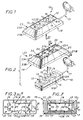
- FIGS. 1-10 illustrate, by way of example, application of the invention in the case where the apparatus electric 10 to be equipped is a power strip, and, more precisely, a mobile multi-socket block permanently equipped a cord 11 suitable for servicing them.
- the housing 12 has, externally, a shape generally globally parallelepipedic, and it is formed of two parts, namely an upper part 12A, on which intervene the socket outlets 13, and a part lower 12B.
- this housing 12 comprises, at least locally, projecting, at its periphery, a bead 15.
- this bead 15 extends annularly all around the periphery of the housing 12, and it is at its favor that is done the relative interlocking with respect to the other of the two parts 12A, 12B constituting this case 12.
- the housing 12 is devoid of any bead at its periphery.
- the housing 12 presents, at its back, that is to say hollow on its lower surface, and, more precisely, on the lower surface of its lower part 12B, a plurality of excavations 16, in the form of a well.
- the recess 19 of the covering 18 has, in plan, a closed contour complementary to the outline presented in plan by the housing 12 of electrical equipment 10 disregarding its possible bead 15.
- this recess 19 opens on the surface by a outlet 22, which is suitable for giving access to the apparatus electric 10 and, more specifically, in this case, to the bases of socket 13 which it comprises, and which, in the forms of shown, extends generally in one plane.
- the covering 18 comprises, peripherally, a skirt 23, which goes globally flaring from outlet 22 of his recess 19, and, for the most part, it is reduced to this skirt 23.
- the covering 18 comprises, successively, from the outlet 22 of the recess 19, an oblique section 23A, which is the upper section, which is generally trunk-pyramidal in practice, and a straight section 23B, which is the section lower, and which, of lower height than the oblique section 23A, is in practice generally cylindrical.
- the edge of the skirt 23, that is to say the lower edge of its straight section 23B, extends in a plane, parallel to that in which the outlet 22 extends the recess 19.
- the skirt 23 At its base, that is to say on the side opposite the outlet 22 of the recess 19, and therefore at the base of its straight section 23B, the skirt 23 has, locally, on its edge, in the embodiments shown, at least one notch 25, for the passage of the cord 11 of the electrical equipment 10.
- notch 25 is provided, and, at the like the cord 11, it acts on one of the sides of narrower width of the straight section 23B of the skirt 23, in the middle area on this side.
- the stop means 20 are intervene the bead 15 of the housing 12 of the apparatus electric 10, and for this purpose they comprise at least one elastically deformable tab 26 having, transversely, to cooperate in restraint with this bead 15 in at least one sense, at least one notch 27A, 27B.
- legs elastically deformable 26 distributed from place to place all around the recess 19, for example, two along each of the two longer sides of this recess 19, as shown, and, to cooperate in restraint with the bead 15 in either direction, these legs elastically deformable 26 all have transversely, on the same level, two notches 27A, 27B, which, turned towards each other, form for each side a groove 28 by which they are all able to come engaged with this bead 15.
- these legs elastically deformable 26 extend freely at the edge of the recess 19, from outlet 22 thereof, and substantially perpendicular to the plane in which this outlet 22 extends.
- the notch 27B which is the one furthest from this outlet 22, is preceded by an oblique chamfer 29.
- the height H1 of the elastically deformable legs 26 to be counted of outlet 22 of recess 19 is less than the height H2 of the skirt 23 from this same outlet 22, and this height H2 is itself at least equal to the height H3 of the box 12 of the electrical equipment 10 between its surfaces upper and lower, preferably being slightly higher than this height H3, Figure 4.
- the recess 19 of the covering 18 according to the invention is delimited, laterally, from place to place, by the legs elastically deformable 26.
- the housing 12 of the electrical equipment 10 is fully engaged, and more precisely embedded, in the recess 19 of the covering 18 according to the invention, in being sort of hanging inside of it.
- this covering 18 forms, at least locally, around its recess 19, and, in practice, all around it, beyond elastically deformable tabs 26, a housing 30.
- the covering 18 then comprises, for the retention of this cord 11, means holding 32 suitable for closing, at least partially, on request, housing 30.
- these holding means 32 comprise at least one bar 33 able to extend, transversely, between two opposite edges of the skirt 23, at the base thereof, over at least part of the distance corresponding.
- two bars 33 are provided, parallel to each other, and at a distance from each other, at the rate of one per end of the housing 12 of the apparatus electric 10.
- the holding means 32 formed by these bars 33 include fitting means 34 suitable for enabling secure them to the housing 12 of the electrical equipment 10.
- these means of fitting 34 are made up of two studs 35 that each of the bars 33 has a protruding distance from each other to cooperate with the two corresponding screwing excavations 16 of the box 12 of the electrical equipment 10.
- the holding means 32 are in one piece with the skirt 23, being permanently linked to it.
- each of these bars 33 is split into two half-bars 33 'each associated respectively to the two opposite opposite edges of the skirt 23.
- the half-bars 33 ′ thus placed work are connected to the edge that presents at its base the skirt 23 by a zone of lesser thickness 36 forming a hinge.
- the holding means 32 thus constituted comprise fitting means 34 formed of pads 35 suitable for securing them to the housing 12 of electrical equipment 10 by engagement in corresponding screwing excavations 16 thereof.
- the oblique chamfer 29 of the legs elastically deformable 26 advantageously facilitates removal of the covering 18 according to the invention when this removal proves necessary, that this removal be done using a common tool, such as for example the blade of a screwdriver, or make it more simple by hand.
- the abutment means 20 provided for retaining the housing 12 of the electrical equipment 10 relative to the covering 18 according to the invention do not cooperate with the bead 15 of this housing 12 and are therefore particularly suitable for the case where, as shown schematically in this figure 9, this housing 12 is in does not have such a bead 15.
- these means stop have a notch 27'A, which, at least locally, protrudes towards the inside of the recess 19.
- this notch 27'A belongs to a lip 37 which, at the outlet 22 of the recess 19, bites on the volume inside of this recess 19.
- this lip 37 extends continuously around the outlet 22 of the recess 19.
- the stop means 20 comprise, in in addition, on the opposite side of the skirt 23, a shoulder 27'B which belongs to the associated holding means 32.
- these means holding 32 are formed by a base 38 capable of closing the skirt 23 completely, at the base thereof.
- these holding means 32 comprise fitting means 39 suitable for enabling them to be report on this skirt 23.
- these interlocking means 39 are constituted by a bead that presents annularly in projecting outwardly a flange 40 of the base 38.
- the base 38 When the base 38 is snapped onto the skirt 23, it jointly ensures, on the one hand, the restraint, in a sense, of the housing 12 of the electrical equipment 10, however that restraint of it in the opposite direction is jointly provided by the notch 27'A formed by the lip 37, and, on the other hand, the retention of the cord 11 of this apparatus electric 10.
- this base 38 presents, locally, on the one hand, hollow on its surface upper, in correspondence with the studs 17 of the housing 12 electrical equipment 10, clearances 43 allowing these pads 17 to be received without interfering with them, and, on the other hand, projecting from its lower surface, 17 'studs, which, in a way, replace the 17 studs precedents.
- the base 38 can also include, at its periphery, one or more notches, not shown, allowing a tool to be inserted between it and the covering 18 current, for example the blade of a screwdriver, to facilitate its deposits, that is to say its separation from the covering 18, when this removal is necessary.
- the present invention is moreover not limited to embodiments described and shown, but encompasses any variant of execution and / or combination of their various elements.
- the covering according to the invention can be at least partly of elastic material.
- the assembly of the two constituent parts of the box of the electrical equipment concerned is not done necessarily by screwing, but can on the contrary be done just as well by another technique, and, for example, by welding or snapping.
- this case can just as easily much more or less overflowing with this covering, both in its part higher than its lower part.
- the bead can just as easily belong to the covering and the notches in the case, unlike the more particularly described and shown.
Abstract
Description
La présente invention concerne d'une manière générale les appareillages électriques, et elle vise plus particulièrement, mais non nécessairement exclusivement, ceux de ces appareillages électriques qui sont à usage domestique.The present invention relates generally electrical equipment, and it targets more particularly, but not necessarily exclusively, those of these electrical appliances which are for domestic use.
C'est le cas, par exemple, des blocs multiprises, qu'il s'agisse de blocs multiprises mobiles ou qu'il s'agisse de blocs multiprises fixes.This is the case, for example, of multiple socket blocks, whether it’s mobile power strips or whether it’s of fixed multiple outlet blocks.
Pour suivre, ou séduire, la clientèle intéressée, et satisfaire ainsi aux exigences du marché, il est souhaitable, pour le fabricant de ces appareillages électriques, de pouvoir faire varier facilement, rapidement et économiquement, leur "esthétique", c'est-à-dire leur aspect extérieur, ou, plus précisément, celui de leur boítier, tant en ce qui concerne la couleur de ce boítier qu'en ce qui concerne sa forme et/ou la nature de la matière qui le constitue.To follow, or attract, interested customers, and thus meet market requirements, it is desirable, for the manufacturer of these electrical devices, to be able easily, quickly and economically vary their "aesthetic", that is to say their external appearance, or, more specifically, that of their case, both with regard to the color of this case as regards its shape and / or the nature of the material which constitutes it.
Le plus communément, à ce jour, il est proposé, pour ce faire, de procéder à un changement de tout ou partie d'un tel boítier, en intervenant par exemple sur son fond et/ou sur son couvercle.Most commonly, to date, it is proposed, for do this, to make a change to all or part of a such case, by intervening for example on its bottom and / or on its cover.
Outre qu'une telle solution implique d'intervenir de manière dispendieuse sur les lignes de fabrication correspondantes, elle ne peut pas s'appliquer aisément aux appareillages électriques déjà existants, sauf à en changer, à chaque fois, de manière également dispendieuse, tout ou partie du boítier. Besides that such a solution implies to intervene expensive on the production lines corresponding, it cannot be easily applied to electrical equipment already existing, except to change it, each time, equally expensive, all or part of the case.
Afin de résoudre les inconvénients précités, le document DE 9314538 U propose un habillage à rapporter sur le boítier d'un tel appareillage.In order to solve the aforementioned drawbacks, the document DE 9314538 U proposes a covering to be brought back on the casing of such an apparatus.
A cet effet, cet habillage comporte, d'une part, un évidement, qui est propre à un engagement de ce boítier, et, d'autre part, des moyens de butée, qui sont propres à intervenir en retenue à l'égard de ce boítier, tant dans un sens que dans l'autre. For this purpose, this covering comprises, on the one hand, a recess, which is suitable for an engagement of this housing, and, on the other hand, stop means, which are suitable to intervene with restraint with regard to this case, both in a sense than in the other.
Par sa seule présence sur le boítier de l'appareillage électrique qu'il équipe, l'habillage modifie de manière sensible, l'aspect extérieur de ce boítier, et, donc, son esthétique.By its mere presence on the switchgear housing electric it equips, the dressing significantly changes the appearance exterior of this case, and, therefore, its aesthetics.
Corollairement, les caractéristiques techniques de cet appareillage électrique, et, notamment, son isolation électrique, sa tenue au feu, et ses autres caractéristiques de sécurité, se trouvent intégralement conservées, la présence de l'habillage n'ayant aucune incidence sur elles.As a corollary, the technical characteristics of this electrical equipment, and in particular its insulation electric, its resistance to fire, and its other characteristics of security, are fully preserved, the presence of the dressing having no effect on them.
L'habillage n'influant en rien sur les caractéristiques techniques de l'appareillage électrique qu'il équipe, il y a, avantageusement, une grande liberté dans le choix du matériau susceptible d'être mis en oeuvre pour sa réalisation.The dressing does not influence nothing about the technical characteristics of the switchgear electric that it equips, there is, advantageously, a large freedom in the choice of material likely to be used work for its realization.
L'appareillage électrique concerné restant par lui-même inchangé, l'habillage peut avantageusement être rapporté sur un appareillage électrique déjà existant, ce qui ouvre avantageusement la possibilité à la clientèle intéressée d'équiper elle-même de cet habillage un tel appareillage électrique, ou de changer à son gré cet habillage, en fonction par exemple de l'environnement dans lequel intervient l'appareillage électrique correspondant.The relevant electrical equipment remaining by itself unchanged, the skin can advantageously be attached to electrical equipment already existing, which advantageously opens up the possibility to customers interested in fitting this dressing themselves such electrical equipment, or to change as desired dressing, depending for example on the environment in which intervenes the corresponding electrical equipment.
Par rapport à l'état de la technique précité l'invention tire un parti supplémentaire d'un tel habillage, en conférant à celui-ci non plus seulement une fonction esthétique, mais également une fonction technique.Compared to the aforementioned prior art takes further advantage of such a skin, by conferring not only an aesthetic function, but also a technical function.
Suivant le développement correspondant de l'invention, l'habillage suivant l'invention est caractérisé par les caractéristiques de la revendication 1.According to the corresponding development of the invention, the covering according to the invention is characterized by the features of claim 1.
Ainsi, la longueur éventuellement excédentaire de ce cordon en cours d'utilisation peut avantageusement être rangée, et dissimulée, dans ce logement, au bénéfice d'une moindre emprise sur l'environnement ambiant.So the possibly excess length of this cord in use can advantageously be stored, and hidden, in this accommodation, for the benefit of a lesser influence over the surrounding environment.
Mais cela peut également être le cas lorsque, par exemple, une certaine protection contre les chocs est recherchée.But this can also be the case when, for example example, some impact protection is sought.
Suivant le développement correspondant de l'invention, l'habillage suivant l'invention est encore caractérisé en ce qu'il est au moins en partie en matière élastique, de type caoutchouc par exemple.According to the corresponding development of the invention, the covering according to the invention is further characterized in that that it is at least partly made of elastic material, of the type rubber for example.
Il est ainsi avantageusement à même d'absorber par lui-même certains chocs.It is thus advantageously able to absorb by itself some shocks.
Les caractéristiques et avantages de l'invention
ressortiront d'ailleurs de la description qui va suivre, à
titre d'exemple, en référence aux dessins schématiques annexés
sur lesquels :
Ces figures illustrent, à titre d'exemple,
l'application de l'invention au cas où l'appareillage
électrique 10 à équiper est un bloc multiprise, et, plus
précisément, un bloc multiprise mobile équipé en permanence
d'un cordon 11 propre à en assurer la desserte.These figures illustrate, by way of example,
application of the invention in the case where the apparatus
electric 10 to be equipped is a power strip, and, more
precisely, a mobile multi-socket block permanently equipped
a
Un tel appareillage électrique 10 étant bien connu par
lui-même, et ne relevant pas en propre de la présente
invention, il ne sera pas décrit dans tous ses détails ici.Such
Il suffira d'indiquer qu'il comporte un boítier 12,
qui présente, en surface, une pluralité de socles de prise de
courant 13 intervenant chacun au fond d'un puits 14, et auquel
est raccordé le cordon 11.It will suffice to indicate that it includes a
Dans les formes de réalisation représentées ou
schématisées, le boítier 12 a, extérieurement, une forme
générale globalement parallélépipédique, et il est formé de
deux parties, à savoir une partie supérieure 12A, sur laquelle
interviennent les socles de prise de courant 13, et une partie
inférieure 12B.In the embodiments shown or
schematically, the
Dans les formes de réalisation plus particulièrement
représentées ou schématisées sur les figures 1 à 8, ce boítier
12 comporte, au moins localement, en saillie, à sa périphérie,
un bourrelet 15.In the embodiments more particularly
shown or shown schematically in Figures 1 to 8, this
En pratique, ce bourrelet 15 s'étend annulairement
tout autour de la périphérie du boítier 12, et c'est à sa
faveur que se fait l'emboítement relatif l'une par rapport à
l'autre des deux parties 12A, 12B constitutives de ce boítier
12.In practice, this
Dans la forme de réalisation schématisée en traits
interrompus sur la figure 9, le boítier 12 est dépourvu de tout
bourrelet à sa périphérie.In the embodiment shown schematically in lines
interrupted in Figure 9, the
Quoi qu'il en soit, dans les formes de réalisation
représentées ou schématisées, le boítier 12 présente, à son
dos, c'est-à-dire en creux sur sa surface inférieure, et, plus
précisément, sur la surface inférieure de sa partie inférieure
12B, une pluralité d'excavations 16, en forme de puits.Anyway, in the embodiments
shown or shown schematically, the
Il s'agit, par exemple, d'excavations de vissage à la
faveur desquelles interviennent les vis assurant l'assemblage
l'une à l'autre des deux parties 12A, 12B du boítier 12.These are, for example, screwing excavations at the
favor of which intervene the screws ensuring the assembly
to each other of the two
Dans les formes de réalisation représentées, quatre
excavations de vissage 16 sont ainsi prévues, à raison de deux
à proximité de chacune des extrémités transversales du boítier
12, et, pour former des plots 17 en saillie sur la surface
inférieure du boítier 12, chacune d'elles est entourée d'un
bourrelet à son débouché.In the embodiments shown, four
Suivant l'invention, il est associé à l'appareillage
électrique 10, un habillage 18, qui est à rapporter sur son
boítier 12, et qui comporte, d'une part, un évidement 19, qui
est propre à un engagement au moins partiel de ce boítier 12,
et, d'autre part, suivant des modalités décrites plus en détail
ultérieurement, des moyens de butée 20, qui sont propres à
intervenir en retenue à l'égard de ce boítier 12, tant dans un
sens que dans l'autre, ces deux sens étant appréciés par
rapport à une même direction qui correspond en pratique
globalement à la direction suivant laquelle le boítier 12 peut
être engagé dans l'évidement 19 de l'habillage 18.According to the invention, it is associated with the apparatus
electric 10, a
Dans les formes de réalisation représentées,
l'évidement 19 de l'habillage 18 a, en plan, un contour fermé
complémentaire du contour que présente en plan le boítier 12
de l'appareillage électrique 10 abstraction faite de son
éventuel bourrelet 15.In the embodiments shown,
the
En pratique, cet évidement 19 ouvre en surface par un
débouché 22, qui est propre à donner accès à l'appareillage
électrique 10 et, plus précisément, en l'espèce, aux socles de
prise de courant 13 qu'il comporte, et qui, dans les formes de
réalisation représentées, s'étend globalement dans un plan.In practice, this
Dans les formes de réalisation représentées,
l'habillage 18 comporte, périphériquement, une jupe 23, qui va
globalement en s'évasant à compter du débouché 22 de son
évidement 19, et, pour l'essentiel, il se réduit à cette jupe
23.In the embodiments shown,
the covering 18 comprises, peripherally, a
Plus précisément, dans ces formes de réalisation,
l'habillage 18 comporte, successivement, à compter du débouché
22 de l'évidement 19, un tronçon oblique 23A, qui en est le
tronçon supérieur, et qui est en pratique globalement tronc-pyramidal,
et un tronçon droit 23B, qui en est le tronçon
inférieur, et qui, de moindre hauteur que le tronçon oblique
23A, est en pratique globalement cylindrique.More specifically, in these embodiments,
the covering 18 comprises, successively, from the
En pratique, la tranche de la jupe 23, c'est-à-dire le
bord inférieur de son tronçon droit 23B, s'étend dans un plan,
parallèle à celui dans lequel s'étend le débouché 22 de
l'évidement 19.In practice, the edge of the
A sa base, c'est-à-dire du côté opposé au débouché 22
de l'évidement 19, et, donc, à la base de son tronçon droit
23B, la jupe 23 comporte, localement, sur sa tranche, dans les
formes de réalisation représentées, au moins une encoche 25,
pour le passage du cordon 11 de l'appareillage électrique 10.At its base, that is to say on the side opposite the
En pratique, une seule encoche 25 est prévue, et, à la
manière du cordon 11, elle intervient sur l'un des côtés de
plus faible largeur du tronçon droit 23B de la jupe 23, dans
la zone médiane de ce côté.In practice, only one
Dans les formes de réalisation plus particulièrement
représentées sur les figures 1 à 8, les moyens de butée 20 font
intervenir le bourrelet 15 du boítier 12 de l'appareillage
électrique 10, et ils comportent, à cet effet, au moins une
patte élastiquement déformable 26 présentant, transversalement,
pour coopérer en retenue avec ce bourrelet 15 dans au moins un
sens, au moins un cran 27A, 27B .In the embodiments more particularly
shown in Figures 1 to 8, the stop means 20 are
intervene the
En pratique, il y a plusieurs pattes élastiquement
déformables 26 réparties de place en place tout autour de
l'évidement 19, à raison, par exemple, de deux le long de
chacun des deux côtés de plus grande longueur de cet évidement
19, tel que représenté, et, pour coopérer en retenue avec le
bourrelet 15 dans l'un et l'autre sens, ces pattes
élastiquement déformables 26 présentent, toutes,
transversalement, à un même niveau, deux crans 27A, 27B, qui,
tournés l'un vers l'autre, forment pour chacune les flancs
d'une rainure 28 par laquelle elles sont toutes aptes à venir
en prise avec ce bourrelet 15.In practice, there are several legs elastically
deformable 26 distributed from place to place all around
the
En pratique, également, ces pattes élastiquement
déformables 26 s'étendent librement en bordure de l'évidement
19, à compter du débouché 22 de celui-ci, et sensiblement
perpendiculairement au plan dans lequel s'étend ce débouché 22.In practice, too, these legs elastically
deformable 26 extend freely at the edge of the
Leurs crans 27A, 27B sont en outre globalement
parallèles à ce plan.Their
Préférentiellement, et tel que représenté, le cran
27B, qui est celui le plus éloigné de ce débouché 22, est
précédé par un chanfrein oblique 29.Preferably, and as shown, the
Dans les formes de réalisation représentées, la
hauteur H1 des pattes élastiquement déformables 26 à compter
du débouché 22 de l'évidement 19 est inférieure à la hauteur
H2 de la jupe 23 à compter de ce même débouché 22, et cette
hauteur H2 est elle-même au moins égale à la hauteur H3 du
boítier 12 de l'appareillage électrique 10 entre ses surfaces
supérieure et inférieure, en étant préférentiellement
légèrement supérieure à cette hauteur H3, figure 4.In the embodiments shown, the
height H1 of the elastically
Il résulte de ce qui précède que l'évidement 19 de
l'habillage 18 suivant l'invention se trouve délimité,
latéralement, de place en place, par les pattes élastiquement
déformables 26.It follows from the above that the
L'engagement du boítier 12 de l'appareillage
électrique 10 dans cet évidement 19 se fait donc par le bas,
c'est-à-dire du côté du tronçon droit 23B de la jupe 23,
suivant la flèche F1 de la figure 2.The engagement of the
Ainsi qu'il est aisé de le comprendre, cet engagement
est facilité par les chanfreins obliques 29 que présentent à
cet effet les pattes élastiquement déformables 26, et il
implique temporairement une déformation élastique de ces
dernières.As is easy to understand, this commitment
is facilitated by the
Par construction, il est fait en sorte, dans les
formes de réalisation représentées sur les figures 1 à 8, que,
lorsque le boítier 12 de l'appareillage électrique 10 est en
place dans l'évidement 19 de l'habillage 18, avec son bourrelet
15 en prise avec la rainure 28 des pattes élastiquement
déformables 26 de celui-ci, il affleure avec le débouché 22 de
cet évidement 19 par la surface supérieure de sa partie
supérieure 12A, cependant que la surface inférieure de sa
partie inférieure 12B se trouve légèrement en retrait par
rapport à la tranche que forme à sa base la jupe 23.By construction, it is made in the
embodiments shown in Figures 1 to 8, that,
when the
Ainsi, dans les formes de réalisation représentées sur
les figures 1 à 8, le boítier 12 de l'appareillage électrique
10 se trouve entièrement engagé, et plus précisément encastré,
dans l'évidement 19 de l'habillage 18 suivant l'invention, en
étant en quelque sorte suspendu à l'intérieur de celui-ci.Thus, in the embodiments shown on
Figures 1 to 8, the
Quoi qu'il en soit, lorsque l'habillage 18 suivant
l'invention est ainsi en place sur le boítier 12 de
l'appareillage électrique 10, tout se passe comme si cet
habillage 18 faisait partie de ce boítier 12.Anyway, when the next 18 skin
the invention is thus in place on the
Il résulte, par ailleurs, de l'évasement de la jupe 23
de l'habillage 18 suivant l'invention, que, intérieurement, cet
habillage 18 forme, au moins localement, autour de son
évidement 19, et, en pratique, tout autour de celui-ci, au-delà
des pattes élastiquement déformables 26, un logement 30.It also results from the flaring of the
Suivant un développement de l'invention, il est tiré
profit de ce logement 30 pour assurer la réception d'une partie
au moins du cordon 11 de l'appareillage électrique 10, par
enroulement de celui-ci autour de l'évidement 19, et, donc,
autour du boítier 12 de cet appareillage électrique 10, tel que
schématisé en traits interrompus à la figure 5 et tel que
représenté en trait continu à la figure 7.According to a development of the invention, it is drawn
take advantage of this
Corollairement, l'habillage 18 suivant l'invention
comporte, alors, pour la retenue de ce cordon 11, des moyens
de maintien 32 propres à permettre de fermer, au moins
partiellement, à la demande, le logement 30.As a corollary, the covering 18 according to the invention
then comprises, for the retention of this
Dans la forme de réalisation plus particulièrement
représentée sur les figures 5 et 6, ces moyens de maintien 32
comportent au moins une barrette 33 apte à s'étendre,
transversalement, entre deux bords opposés de la jupe 23, à la
base de celle-ci, sur une partie au moins de la distance
correspondante.In the embodiment more particularly
shown in Figures 5 and 6, these holding means 32
comprise at least one
En pratique, deux barrettes 33 sont prévues,
parallèlement l'une à l'autre, et à distance l'une de l'autre,
à raison d'une par extrémité du boítier 12 de l'appareillage
électrique 10.In practice, two
Corollairement, dans cette forme de réalisation, les
moyens de maintien 32 que constituent ces barrettes 33
comportent des moyens d'emboítement 34 propres à permettre de
les assujettir au boítier 12 de l'appareillage électrique 10.As a corollary, in this embodiment, the
holding means 32 formed by these
En pratique, ces moyens d'emboítement 34 sont
constitués de deux plots 35 que chacune des barrettes 33
comporte en saillie à distance l'un de l'autre pour coopérer
avec les deux excavations de vissage 16 correspondantes du
boítier 12 de l'appareillage électrique 10.In practice, these means of fitting 34 are
made up of two
Tel que schématisé en traits interrompus pour l'une
d'elles sur la figure 5, les barrettes 33 peuvent ainsi être
rapportées sur ce boítier 12, suivant la flèche F2 de cette
figure 5. As shown in broken lines for one
of them in FIG. 5, the
Elles s'étendent alors en porte à faux par rapport à celui-ci.They then extend cantilevered relative to this one.
Ainsi qu'il est aisé de le comprendre, il n'est dès
lors pas nécessaire qu'elles s'étendent sur toute la distance
séparant l'un de l'autre les deux bords concernés de la jupe
23 de l'habillage 18.As is easy to understand, it is not
when not necessary that they extend over the entire distance
separating the two relevant edges of the skirt from one another
23 of the
Elles peuvent au contraire rester à distance de l'un
et/ou de l'autre de ces bords, pourvu que l'éventuel espace
correspondant ne soit pas suffisant pour laisser échapper le
cordon 11 de l'appareillage électrique 10.On the contrary, they can stay away from one
and / or the other of these edges, provided that the possible space
correspondent is not enough to let the
Dans la forme de réalisation représentée sur la figure
8, les moyens de maintien 32 sont d'un seul tenant avec la jupe
23, en étant articulés à demeure à celle-ci.In the embodiment shown in the figure
8, the holding means 32 are in one piece with the
Il s'agit, par exemple, de deux barrettes 33, qui,
comme précédemment, s'étendent parallèlement l'une à l'autre,
et à distance l'une de l'autre, mais, dans la forme de
réalisation représentée, chacune de ces barrettes 33 est
fractionnée en deux demi-barrettes 33' associées chacune
respectivement aux deux bords opposés concernés de la jupe 23.These are, for example, two
En pratique, les demi-barrettes 33' ainsi mises en
oeuvre se raccordent à la tranche que présente à sa base la
jupe 23 par une zone de moindre épaisseur 36 formant charnière.In practice, the half-
Par pivotement autour de cette zone de moindre
épaisseur 36, et tel que schématisé par une flèche F3 pour
l'une d'elles sur la figure 8, elles peuvent passer d'une
position d'ouverture, du type de celle représentée sur la
partie de droite de cette figure 8, à une position de
fermeture, pour laquelle, tel que représenté sur la partie de
gauche de la figure 8, elles viennent s'appliquer sur le
boítier 12 de l'appareillage électrique 10.By pivoting around this area of
Comme précédemment, les moyens de maintien 32 ainsi
constitués comportent des moyens d'emboítement 34 formés de
plots 35 propres à les assujettir au boítier 12 de
l'appareillage électrique 10 par engagement dans les
excavations de vissage 16 correspondantes de celui-ci.As before, the holding means 32 thus
constituted comprise fitting means 34 formed of
Il va de soi que, suivant une variante de réalisation
non représentée, il peut être substitué aux demi-barrettes 33'
des volets s'étendant sur toute la longueur de la jupe 23.It goes without saying that, according to an alternative embodiment
not shown, it can be substituted for the half-bars 33 '
flaps extending over the entire length of the
Dans tous les cas, le chanfrein oblique 29 des pattes
élastiquement déformables 26 facilite avantageusement la dépose
de l'habillage 18 suivant l'invention lorsque cette dépose
s'avère nécessaire, que cette dépose se fasse à l'aide d'un
outil courant, tel que par exemple la lame d'un tournevis, ou
qu'elle se fasse plus simplement à la main.In all cases, the
Dans la forme de réalisation représentée sur la figure
9, les moyens de butée 20 prévus pour la retenue du boítier 12
de l'appareillage électrique 10 par rapport à l'habillage 18
suivant l'invention ne coopèrent pas avec le bourrelet 15 de
ce boítier 12 et conviennent donc tout particulièrement au cas
où, comme schématisé sur cette figure 9, ce boítier 12 est en
fait dépourvu d'un tel bourrelet 15.In the embodiment shown in the figure
9, the abutment means 20 provided for retaining the
Dans la forme de réalisation représentée, ces moyens
de butée comportent un cran 27'A, qui, au moins localement,
fait saillie vers l'intérieur de l'évidement 19.In the embodiment shown, these means
stop have a notch 27'A, which, at least locally,
protrudes towards the inside of the
En pratique, ce cran 27'A appartient à une lèvre 37
qui, au débouché 22 de l'évidement 19, mord sur le volume
intérieur de cet évidement 19.In practice, this notch 27'A belongs to a
Préférentiellement, et tel que représenté, cette lèvre
37 s' étend en continu tout autour du débouché 22 de l'évidement
19.Preferably, and as shown, this
Conjointement, les moyens de butée 20 comportent, en
outre, du côté opposé de la jupe 23, un épaulement 27'B qui
appartient aux moyens de maintien 32 associés.Jointly, the stop means 20 comprise, in
in addition, on the opposite side of the
Dans la forme de réalisation représentée, ces moyens
de maintien 32 sont formés par une embase 38 apte à fermer
complètement la jupe 23, à la base de celle-ci.In the embodiment shown, these means
holding 32 are formed by a base 38 capable of closing
the
Pour ce faire, ces moyens de maintien 32 comportent
des moyens d'emboítement 39 propres à permettre de les
rapporter sur cette jupe 23.To do this, these holding means 32 comprise
fitting means 39 suitable for enabling them to be
report on this
En pratique, ces moyens d'emboítement 39 sont
constitués par un bourrelet que présente annulairement en
saillie vers l'extérieur un rebord 40 de l'embase 38.In practice, these interlocking means 39 are
constituted by a bead that presents annularly in
projecting outwardly a
Conjointement, la jupe 23, et plus précisément le
tronçon droit 23B de celle-ci, présente, annulairement, en
creux sur sa surface intérieure, une gorge 42, qui est
complémentaire du bourrelet constituant les moyens
d'emboítement 39 associés, et avec laquelle ce bourrelet est
apte à coopérer en engagement par simple encliquetage.Jointly, the
Lorsque l'embase 38 est encliquetée sur la jupe 23,
elle assure conjointement, d'une part, la retenue, dans un
sens, du boítier 12 de l'appareillage électrique 10, cependant
que la retenue de celui-ci dans le sens opposé est
conjointement assurée par le cran 27'A que forme la lèvre 37,
et, d'autre part, la retenue du cordon 11 de cet appareillage
électrique 10.When the
Dans la forme de réalisation représentée, cette embase
38 présente, localement, d'une part, en creux sur sa surface
supérieure, en correspondance avec les plots 17 du boítier 12
de l'appareillage électrique 10, des dégagements 43 lui
permettant de recevoir ces plots 17 sans interférer avec ceux-ci,
et, d'autre part, en saillie sur sa surface inférieure, des
plots 17', qui, en quelque sorte, se substituent aux plots 17
précédents.In the embodiment shown, this
Si désiré, l'embase 38 peut également comporter, à sa
périphérie, une ou plusieurs encoches, non représentées,
permettant d'insérer entre elle et l'habillage 18 un outil
courant, par exemple la lame d'un tournevis, pour faciliter sa
dépose, c'est-à-dire sa désolidarisation vis-à-vis de
l'habillage 18, lorsque que cette dépose est nécessaire.If desired, the
La présente invention ne se limite d'ailleurs pas aux formes de réalisation décrites et représentées, mais englobe toute variante d' exécution et/ou de combinaison de leurs divers éléments.The present invention is moreover not limited to embodiments described and shown, but encompasses any variant of execution and / or combination of their various elements.
Par exemple, dans le cas où une protection contre les chocs est recherchée, l'habillage suivant l'invention peut être au moins en partie en matière élastique.For example, in the event that protection against shocks is sought, the covering according to the invention can be at least partly of elastic material.
En outre, l'assemblage des deux parties constitutives du boítier de l'appareillage électrique concerné ne se fait pas nécessairement par vissage, mais peut au contraire se faire tout aussi bien par une autre technique, et, par exemple, par soudage ou encliquetage. In addition, the assembly of the two constituent parts of the box of the electrical equipment concerned is not done necessarily by screwing, but can on the contrary be done just as well by another technique, and, for example, by welding or snapping.
Par ailleurs, au lieu d'être totalement engagé dans l'habillage suivant l'invention, ce boítier peut tout aussi bien plus ou moins déborder de cet habillage, tant à sa partie supérieure qu'à sa partie inférieure.Furthermore, instead of being fully engaged in the covering according to the invention, this case can just as easily much more or less overflowing with this covering, both in its part higher than its lower part.
Enfin, lorsque, entre cet habillage et ce boítier, un engagement se fait entre un bourrelet et des crans, le bourrelet peut tout aussi bien appartenir à l'habillage et les crans au boítier, à l'inverse de la disposition plus particulièrement décrite et représentée.Finally, when, between this covering and this case, a engagement is made between a bead and notches, the bead can just as easily belong to the covering and the notches in the case, unlike the more particularly described and shown.
Claims (23)
- Cover for a casing (12) of an electrical appliance (10) comprising a recess (19) capable of engaging with said casing (12) and abutment means (20) capable of retaining said casing (12) in both directions, characterized in that internally, the cover at least locally forms a housing (30) around its recess (19) for receiving at least a portion of any cable (11) serving the electrical appliance in question (10).
- Cover according to claim 1, characterized in that the housing (30) extends completely around said recess (19).
- Cover according to claim 1 or claim 2, characterized in that since its recess (19) opens at the surface via an orifice (22to provide access to the electrical appliance in question (10), it comprises at its periphery a skirt (23) which overall, flares out from said orifice (22).
- Cover according to claim 3, characterized in that said skirt (23) comprises, in succession from said orifice (22), an oblique section (23A) then a vertical section (23B).
- Cover according to claim 3 or claim 4, characterized in that the skirt (23) locally comprises at its base at least one notch (25) for passage of the cable (11), optionally serving the electrical appliance (10) in question.
- Cover according to any one of claims 3 to 5, characterized in that it comprises holding means (32) which can at least partially close the housing (30) on demand.
- Cover according to claim 6, characterized in that the holding means (32) comprise fitting means (34) that allow them to be fixed to the casing (12) of the electrical appliance (10) in question.
- Cover according to claim 6, characterized in that the holding means (32) comprise fitting means (39) that enable then to be applied to the skirt (23).
- Cover according to claim 6, characterized in that the holding means (32) are formed as a single piece with the skirt (23) and are permanently articulated thereon.
- Cover according to any one of claims 7 to 9, characterized in that the holding means (32) comprise at least one strip (33) that can extend transversely between two opposed edges of the skirt (23) at the base thereof over at least a portion of the corresponding distance.
- Cover according to claim 10, characterized in that the strip (33) is divided into two half-strips (33') each respectively associated with the two opposed edges of the skirt (23).
- Cover according to claim 10 or claim 11, characterized in that the holding means (32) comprise two strips (33) which extend parallel to each other at a distance from each other.
- Cover according to any one of claims 7 to 9, characterized in that the holding means (32) are formed by a base (38) that can completely close the skirt (23) at the base thereof.
- Cover according to any one of claims 1 to 13, characterized in that it comprises abutment means (20) that can cooperate with a bead (15) extending at least locally and projecting from the periphery of the casing (12) of the electrical appliance in question.
- Cover according to claim 14, characterized in that the abutment means (20) comprise at least one elastically deformable tab (26) having at least one transverse notch (27A, 27B) to retain the bead (15) of the casing (12) of the electrical appliance in question (10) in at least one direction.
- Cover according to claim 15, characterized in that in order to cooperate in both directions with the bead (15) of the casing (12) of the electrical appliance in question (10), the elastically deformable tab (26) has two transverse notches (27A, 27B) which are turned towards each other to form the flanks of a groove (28) via which it can come into contact with said bead (15).
- Cover according to claim 15 or claim 16, characterized in that, since its recess (19) opens at the surface via an orifice (22) to provide access to the electrical appliance in question, the elastically deformable tab (26) extends freely at the edge of said recess (19) from said orifice (22).
- Cover according to any one of claims 15 to 17, characterized in that a plurality of elastically deformable tabs (16) are distributed about said recess (19).
- Cover according to any one of claims 1 to 13, characterized in that the abutment means (20) comprise a notch (27'A) which, at least locally, projects towards the interior of said recess (19).
- Cover according to claim 19, characterized in that, since its recess (19) opens at the surface via an orifice (22) to provide access to the electrical appliance in question, the notch (27'A) forms part of a lip (37) which at said orifice (22) goes over into the inner volume of said recess (19).
- Cover according to claim 19, characterized in that the lip (37) extends completely around the orifice (22) of the recess (19).
- Cover according to claims 8 to 19, taken in combination, characterized in that the abutment means (20) comprise a shoulder (27'B) forming part of the holding means (32).
- Cover according to any one of claims 1 to 22, characterized in that it is at least partially formed from an elastic material.
Applications Claiming Priority (2)
| Application Number | Priority Date | Filing Date | Title |
|---|---|---|---|
| FR9604793 | 1996-04-17 | ||
| FR9604793A FR2747875B1 (en) | 1996-04-17 | 1996-04-17 | COVER TO BE REPORTED ON THE HOUSING OF AN ELECTRICAL EQUIPMENT, AND APPLICATION, IN PARTICULAR, TO MULTIPURPOSE BLOCKS |
Publications (2)
| Publication Number | Publication Date |
|---|---|
| EP0802585A1 EP0802585A1 (en) | 1997-10-22 |
| EP0802585B1 true EP0802585B1 (en) | 2003-11-19 |
Family
ID=9491283
Family Applications (1)
| Application Number | Title | Priority Date | Filing Date |
|---|---|---|---|
| EP97400839A Expired - Lifetime EP0802585B1 (en) | 1996-04-17 | 1997-04-14 | Cover for the housing of an electrical device, in particular for multi-socket outlets |
Country Status (8)
| Country | Link |
|---|---|
| EP (1) | EP0802585B1 (en) |
| AT (1) | ATE254810T1 (en) |
| DE (1) | DE69726215T2 (en) |
| ES (1) | ES2208839T3 (en) |
| FR (1) | FR2747875B1 (en) |
| HU (1) | HU223357B1 (en) |
| PL (1) | PL183207B1 (en) |
| PT (1) | PT802585E (en) |
Families Citing this family (5)
| Publication number | Priority date | Publication date | Assignee | Title |
|---|---|---|---|---|
| WO2002013332A1 (en) * | 2000-08-08 | 2002-02-14 | Arçelik A.S. | Multi-purpose plug-socket assembly |
| MY126338A (en) * | 2000-10-19 | 2006-09-29 | Yap Wang Han | An inverted t-shape multiple socket outlets device, convertible to an extension multiple socket outlets device |
| FR2820889B1 (en) * | 2001-02-14 | 2004-04-02 | Sdg Ind Ltd | MULTI-SOCKET CONNECTOR |
| MY137394A (en) * | 2002-04-18 | 2009-01-30 | Yap Wang Han | Extension socket device with a cord storage and dispensing system |
| IT201700050827A1 (en) * | 2017-05-10 | 2018-11-10 | Fanton S P A | MULTIPURPOSE WITH HARVEST CABINET |
Citations (4)
| Publication number | Priority date | Publication date | Assignee | Title |
|---|---|---|---|---|
| DE2638617A1 (en) * | 1976-08-27 | 1978-03-02 | Bbc Brown Boveri & Cie | Multiple socket for auxiliary electric equipment - is mounted under protective cover with extension cable and plugs and can include switch |
| DE9314538U1 (en) * | 1993-09-25 | 1993-12-16 | Schroll Stefan | Power strip holder in the shape of an animal |
| DE4433443A1 (en) * | 1993-10-05 | 1995-04-06 | Gerhard Seewald | Movable plug socket |
| WO1995020830A1 (en) * | 1994-01-31 | 1995-08-03 | Bato Trading Bv | Spatter, dust and rain-proof plastic safety case intended for extension cord plugging |
Family Cites Families (3)
| Publication number | Priority date | Publication date | Assignee | Title |
|---|---|---|---|---|
| DE7714336U1 (en) * | 1977-05-06 | 1977-08-18 | Steinmueller, Kurt, 5880 Luedenscheid | Table socket |
| DE7908624U1 (en) * | 1979-03-27 | 1980-06-04 | Gebrueder Merten Gmbh & Co Kg, 5270 Gummersbach | Holding device for a movable socket, especially a multiple socket |
| US4705342A (en) * | 1985-11-12 | 1987-11-10 | Cable Electric Products, Inc. | Electrical extension outlet |
-
1996
- 1996-04-17 FR FR9604793A patent/FR2747875B1/en not_active Expired - Lifetime
-
1997
- 1997-04-14 PT PT97400839T patent/PT802585E/en unknown
- 1997-04-14 ES ES97400839T patent/ES2208839T3/en not_active Expired - Lifetime
- 1997-04-14 PL PL97319474A patent/PL183207B1/en not_active IP Right Cessation
- 1997-04-14 DE DE69726215T patent/DE69726215T2/en not_active Expired - Fee Related
- 1997-04-14 AT AT97400839T patent/ATE254810T1/en not_active IP Right Cessation
- 1997-04-14 EP EP97400839A patent/EP0802585B1/en not_active Expired - Lifetime
- 1997-04-16 HU HU9700763A patent/HU223357B1/en not_active IP Right Cessation
Patent Citations (4)
| Publication number | Priority date | Publication date | Assignee | Title |
|---|---|---|---|---|
| DE2638617A1 (en) * | 1976-08-27 | 1978-03-02 | Bbc Brown Boveri & Cie | Multiple socket for auxiliary electric equipment - is mounted under protective cover with extension cable and plugs and can include switch |
| DE9314538U1 (en) * | 1993-09-25 | 1993-12-16 | Schroll Stefan | Power strip holder in the shape of an animal |
| DE4433443A1 (en) * | 1993-10-05 | 1995-04-06 | Gerhard Seewald | Movable plug socket |
| WO1995020830A1 (en) * | 1994-01-31 | 1995-08-03 | Bato Trading Bv | Spatter, dust and rain-proof plastic safety case intended for extension cord plugging |
Also Published As
| Publication number | Publication date |
|---|---|
| PT802585E (en) | 2004-03-31 |
| ES2208839T3 (en) | 2004-06-16 |
| PL183207B1 (en) | 2002-06-28 |
| HU223357B1 (en) | 2004-06-28 |
| HU9700763D0 (en) | 1997-05-28 |
| PL319474A1 (en) | 1997-10-27 |
| FR2747875A1 (en) | 1997-10-24 |
| DE69726215D1 (en) | 2003-12-24 |
| DE69726215T2 (en) | 2004-08-26 |
| FR2747875B1 (en) | 1998-07-03 |
| HUP9700763A2 (en) | 1998-01-28 |
| EP0802585A1 (en) | 1997-10-22 |
| HUP9700763A3 (en) | 2000-03-28 |
| ATE254810T1 (en) | 2003-12-15 |
Similar Documents
| Publication | Publication Date | Title |
|---|---|---|
| FR2913525A1 (en) | Circuit breaker case for power system, comprises case, terminal block portion, and door engaged with case in monolithic form | |
| EP0505256A2 (en) | Two part adapter for connection of an electrical apparatus by plug and socket | |
| FR2464573A1 (en) | BODY FOR ELECTRICAL CONNECTION PLUG | |
| EP0802585B1 (en) | Cover for the housing of an electrical device, in particular for multi-socket outlets | |
| EP1149447B1 (en) | Apparatus support, in particular for electrical apparatus, and box comprising such an apparatus support | |
| WO2016012699A1 (en) | Trim for electric switch and electric switch with such trim | |
| EP0753872B1 (en) | Housing for an electrical apparatus | |
| EP0915537B1 (en) | Electrical flush mount apparatus with clamping-jaws for attachment | |
| WO2005112204A1 (en) | Electrical enclosure with a rotatable locking mechanism and methods for assembling and dismantling same | |
| EP2958195B1 (en) | Modular device for communication box | |
| FR2754383A1 (en) | FUSE HOLDER WITH TEST SOCKETS AND, IF REQUIRED, INDICATOR | |
| EP0752746B1 (en) | Process for modifying the size of an opening in an accessory for electrical ducts and associated accessory | |
| CA2138239A1 (en) | Multiple plug connector base | |
| EP0797271B1 (en) | Base for current socket | |
| FR2703843A1 (en) | Power socket | |
| EP1400195B1 (en) | Domestic appliance consisting of hinged sections | |
| FR3002088A1 (en) | Electrical contact for socket-outlet for e.g. dwelling, has cell extending according to perpendicular direction with respect to longitudinal axis when part is encased in another part | |
| BE1011960A3 (en) | Housing for broadcast aligned assembly of two electrical appliances. | |
| FR2772202A1 (en) | CLAW FIXING ACCESSORY, IN PARTICULAR FOR A RECESSED BOX, AND CORRESPONDING RECESSED BOX | |
| FR2687018A1 (en) | Modular terminal box, in particular for domestic electrical appliances, and wiring system comprising this terminal box | |
| FR2765660A1 (en) | Quick release protective cage for emergency lighting | |
| FR2706548A1 (en) | Articulated spring return assembly, its mounting method, and applications, in particular to boxes for electrical equipment. | |
| FR2669779A1 (en) | Parallel outlet socket for a transmission network, particularly for a telephony or data network | |
| FR2794577A1 (en) | BOX FOR ELECTRICAL EQUIPMENT, LINKED BETWEEN THE TWO ELEMENTS THAT CONSTITUTE IT | |
| FR2757606A1 (en) | LUMINAIRE, IN PARTICULAR AUTONOMOUS SAFETY LIGHTING BLOCK |
Legal Events
| Date | Code | Title | Description |
|---|---|---|---|
| PUAI | Public reference made under article 153(3) epc to a published international application that has entered the european phase |
Free format text: ORIGINAL CODE: 0009012 |
|
| AK | Designated contracting states |
Kind code of ref document: A1 Designated state(s): AT BE DE ES GR IT NL PT |
|
| 17P | Request for examination filed |
Effective date: 19971129 |
|
| 17Q | First examination report despatched |
Effective date: 20020211 |
|
| GRAH | Despatch of communication of intention to grant a patent |
Free format text: ORIGINAL CODE: EPIDOS IGRA |
|
| RTI1 | Title (correction) |
Free format text: COVER FOR THE HOUSING OF AN ELECTRICAL DEVICE, IN PARTICULAR FOR MULTI-SOCKET OUTLETS |
|
| GRAS | Grant fee paid |
Free format text: ORIGINAL CODE: EPIDOSNIGR3 |
|
| GRAA | (expected) grant |
Free format text: ORIGINAL CODE: 0009210 |
|
| AK | Designated contracting states |
Kind code of ref document: B1 Designated state(s): AT BE DE ES GR IT NL PT |
|
| REF | Corresponds to: |
Ref document number: 69726215 Country of ref document: DE Date of ref document: 20031224 Kind code of ref document: P |
|
| REG | Reference to a national code |
Ref country code: GR Ref legal event code: EP Ref document number: 20040400353 Country of ref document: GR |
|
| REG | Reference to a national code |
Ref country code: PT Ref legal event code: SC4A Free format text: AVAILABILITY OF NATIONAL TRANSLATION Effective date: 20040126 |
|
| REG | Reference to a national code |
Ref country code: ES Ref legal event code: FG2A Ref document number: 2208839 Country of ref document: ES Kind code of ref document: T3 |
|
| PLBE | No opposition filed within time limit |
Free format text: ORIGINAL CODE: 0009261 |
|
| STAA | Information on the status of an ep patent application or granted ep patent |
Free format text: STATUS: NO OPPOSITION FILED WITHIN TIME LIMIT |
|
| 26N | No opposition filed |
Effective date: 20040820 |
|
| PGFP | Annual fee paid to national office [announced via postgrant information from national office to epo] |
Ref country code: AT Payment date: 20050317 Year of fee payment: 9 |
|
| PGFP | Annual fee paid to national office [announced via postgrant information from national office to epo] |
Ref country code: NL Payment date: 20050322 Year of fee payment: 9 |
|
| PGFP | Annual fee paid to national office [announced via postgrant information from national office to epo] |
Ref country code: GR Payment date: 20050331 Year of fee payment: 9 |
|
| PGFP | Annual fee paid to national office [announced via postgrant information from national office to epo] |
Ref country code: DE Payment date: 20050408 Year of fee payment: 9 |
|
| PGFP | Annual fee paid to national office [announced via postgrant information from national office to epo] |
Ref country code: PT Payment date: 20050412 Year of fee payment: 9 |
|
| PGFP | Annual fee paid to national office [announced via postgrant information from national office to epo] |
Ref country code: ES Payment date: 20050414 Year of fee payment: 9 |
|
| PGFP | Annual fee paid to national office [announced via postgrant information from national office to epo] |
Ref country code: BE Payment date: 20050429 Year of fee payment: 9 |
|
| PG25 | Lapsed in a contracting state [announced via postgrant information from national office to epo] |
Ref country code: AT Free format text: LAPSE BECAUSE OF NON-PAYMENT OF DUE FEES Effective date: 20060414 |
|
| PG25 | Lapsed in a contracting state [announced via postgrant information from national office to epo] |
Ref country code: ES Free format text: LAPSE BECAUSE OF NON-PAYMENT OF DUE FEES Effective date: 20060415 |
|
| PG25 | Lapsed in a contracting state [announced via postgrant information from national office to epo] |
Ref country code: BE Free format text: LAPSE BECAUSE OF NON-PAYMENT OF DUE FEES Effective date: 20060430 |
|
| PGFP | Annual fee paid to national office [announced via postgrant information from national office to epo] |
Ref country code: IT Payment date: 20060430 Year of fee payment: 10 |
|
| PG25 | Lapsed in a contracting state [announced via postgrant information from national office to epo] |
Ref country code: PT Free format text: LAPSE BECAUSE OF NON-PAYMENT OF DUE FEES Effective date: 20061016 |
|
| PG25 | Lapsed in a contracting state [announced via postgrant information from national office to epo] |
Ref country code: NL Free format text: LAPSE BECAUSE OF NON-PAYMENT OF DUE FEES Effective date: 20061101 Ref country code: DE Free format text: LAPSE BECAUSE OF NON-PAYMENT OF DUE FEES Effective date: 20061101 |
|
| REG | Reference to a national code |
Ref country code: PT Ref legal event code: MM4A Free format text: LAPSE DUE TO NON-PAYMENT OF FEES Effective date: 20061016 |
|
| NLV4 | Nl: lapsed or anulled due to non-payment of the annual fee |
Effective date: 20061101 |
|
| REG | Reference to a national code |
Ref country code: ES Ref legal event code: FD2A Effective date: 20060415 |
|
| BERE | Be: lapsed |
Owner name: *LEGRAND SNC Effective date: 20060430 Owner name: *LEGRAND Effective date: 20060430 |
|
| PG25 | Lapsed in a contracting state [announced via postgrant information from national office to epo] |
Ref country code: GR Free format text: LAPSE BECAUSE OF NON-PAYMENT OF DUE FEES Effective date: 20061102 |
|
| PG25 | Lapsed in a contracting state [announced via postgrant information from national office to epo] |
Ref country code: IT Free format text: LAPSE BECAUSE OF NON-PAYMENT OF DUE FEES Effective date: 20070414 |