EP0802585B1 - Abdeckung für das Gehäuse eines elektrischen Gerätes, insbesondere für Steckdosenleisten - Google Patents
Abdeckung für das Gehäuse eines elektrischen Gerätes, insbesondere für Steckdosenleisten Download PDFInfo
- Publication number
- EP0802585B1 EP0802585B1 EP97400839A EP97400839A EP0802585B1 EP 0802585 B1 EP0802585 B1 EP 0802585B1 EP 97400839 A EP97400839 A EP 97400839A EP 97400839 A EP97400839 A EP 97400839A EP 0802585 B1 EP0802585 B1 EP 0802585B1
- Authority
- EP
- European Patent Office
- Prior art keywords
- cover according
- recess
- skirt
- electrical appliance
- question
- Prior art date
- Legal status (The legal status is an assumption and is not a legal conclusion. Google has not performed a legal analysis and makes no representation as to the accuracy of the status listed.)
- Expired - Lifetime
Links
- 239000011324 bead Substances 0.000 claims description 21
- 239000013013 elastic material Substances 0.000 claims description 3
- 238000009412 basement excavation Methods 0.000 description 5
- 230000008901 benefit Effects 0.000 description 4
- 230000004308 accommodation Effects 0.000 description 2
- 230000000295 complement effect Effects 0.000 description 2
- 230000000694 effects Effects 0.000 description 2
- 230000014759 maintenance of location Effects 0.000 description 2
- 239000000463 material Substances 0.000 description 2
- 238000000034 method Methods 0.000 description 2
- 230000035939 shock Effects 0.000 description 2
- 239000000470 constituent Substances 0.000 description 1
- 238000010276 construction Methods 0.000 description 1
- 230000005489 elastic deformation Effects 0.000 description 1
- 238000009434 installation Methods 0.000 description 1
- 238000009413 insulation Methods 0.000 description 1
- 230000002452 interceptive effect Effects 0.000 description 1
- 238000002955 isolation Methods 0.000 description 1
- 238000004519 manufacturing process Methods 0.000 description 1
- 238000000926 separation method Methods 0.000 description 1
- 238000003860 storage Methods 0.000 description 1
- 238000003466 welding Methods 0.000 description 1
- 238000004804 winding Methods 0.000 description 1
Images

Classifications
-
- H—ELECTRICITY
- H01—ELECTRIC ELEMENTS
- H01R—ELECTRICALLY-CONDUCTIVE CONNECTIONS; STRUCTURAL ASSOCIATIONS OF A PLURALITY OF MUTUALLY-INSULATED ELECTRICAL CONNECTING ELEMENTS; COUPLING DEVICES; CURRENT COLLECTORS
- H01R13/00—Details of coupling devices of the kinds covered by groups H01R12/70 or H01R24/00 - H01R33/00
- H01R13/72—Means for accommodating flexible lead within the holder
-
- H—ELECTRICITY
- H01—ELECTRIC ELEMENTS
- H01R—ELECTRICALLY-CONDUCTIVE CONNECTIONS; STRUCTURAL ASSOCIATIONS OF A PLURALITY OF MUTUALLY-INSULATED ELECTRICAL CONNECTING ELEMENTS; COUPLING DEVICES; CURRENT COLLECTORS
- H01R25/00—Coupling parts adapted for simultaneous co-operation with two or more identical counterparts, e.g. for distributing energy to two or more circuits
- H01R25/003—Coupling parts adapted for simultaneous co-operation with two or more identical counterparts, e.g. for distributing energy to two or more circuits the coupling part being secured only to wires or cables
Definitions
- the present invention relates generally electrical equipment, and it targets more particularly, but not necessarily exclusively, those of these electrical appliances which are for domestic use.
- the document DE 9314538 U proposes a covering to be brought back on the casing of such an apparatus.
- this covering comprises, on the one hand, a recess, which is suitable for an engagement of this housing, and, on the other hand, stop means, which are suitable to intervene with restraint with regard to this case, both in a sense than in the other.
- the dressing By its mere presence on the switchgear housing electric it equips, the dressing significantly changes the appearance exterior of this case, and, therefore, its aesthetics.
- the dressing does not influence nothing about the technical characteristics of the switchgear electric that it equips, there is, advantageously, a large freedom in the choice of material likely to be used work for its realization.
- the skin can advantageously be attached to electrical equipment already existing, which advantageously opens up the possibility to customers interested in fitting this dressing themselves such electrical equipment, or to change as desired dressing, depending for example on the environment in which intervenes the corresponding electrical equipment.
- the covering according to the invention is characterized by the features of claim 1.
- the covering according to the invention is further characterized in that that it is at least partly made of elastic material, of the type rubber for example.
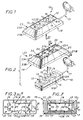
- FIGS. 1-10 illustrate, by way of example, application of the invention in the case where the apparatus electric 10 to be equipped is a power strip, and, more precisely, a mobile multi-socket block permanently equipped a cord 11 suitable for servicing them.
- the housing 12 has, externally, a shape generally globally parallelepipedic, and it is formed of two parts, namely an upper part 12A, on which intervene the socket outlets 13, and a part lower 12B.
- this housing 12 comprises, at least locally, projecting, at its periphery, a bead 15.
- this bead 15 extends annularly all around the periphery of the housing 12, and it is at its favor that is done the relative interlocking with respect to the other of the two parts 12A, 12B constituting this case 12.
- the housing 12 is devoid of any bead at its periphery.
- the housing 12 presents, at its back, that is to say hollow on its lower surface, and, more precisely, on the lower surface of its lower part 12B, a plurality of excavations 16, in the form of a well.
- the recess 19 of the covering 18 has, in plan, a closed contour complementary to the outline presented in plan by the housing 12 of electrical equipment 10 disregarding its possible bead 15.
- this recess 19 opens on the surface by a outlet 22, which is suitable for giving access to the apparatus electric 10 and, more specifically, in this case, to the bases of socket 13 which it comprises, and which, in the forms of shown, extends generally in one plane.
- the covering 18 comprises, peripherally, a skirt 23, which goes globally flaring from outlet 22 of his recess 19, and, for the most part, it is reduced to this skirt 23.
- the covering 18 comprises, successively, from the outlet 22 of the recess 19, an oblique section 23A, which is the upper section, which is generally trunk-pyramidal in practice, and a straight section 23B, which is the section lower, and which, of lower height than the oblique section 23A, is in practice generally cylindrical.
- the edge of the skirt 23, that is to say the lower edge of its straight section 23B, extends in a plane, parallel to that in which the outlet 22 extends the recess 19.
- the skirt 23 At its base, that is to say on the side opposite the outlet 22 of the recess 19, and therefore at the base of its straight section 23B, the skirt 23 has, locally, on its edge, in the embodiments shown, at least one notch 25, for the passage of the cord 11 of the electrical equipment 10.
- notch 25 is provided, and, at the like the cord 11, it acts on one of the sides of narrower width of the straight section 23B of the skirt 23, in the middle area on this side.
- the stop means 20 are intervene the bead 15 of the housing 12 of the apparatus electric 10, and for this purpose they comprise at least one elastically deformable tab 26 having, transversely, to cooperate in restraint with this bead 15 in at least one sense, at least one notch 27A, 27B.
- legs elastically deformable 26 distributed from place to place all around the recess 19, for example, two along each of the two longer sides of this recess 19, as shown, and, to cooperate in restraint with the bead 15 in either direction, these legs elastically deformable 26 all have transversely, on the same level, two notches 27A, 27B, which, turned towards each other, form for each side a groove 28 by which they are all able to come engaged with this bead 15.
- these legs elastically deformable 26 extend freely at the edge of the recess 19, from outlet 22 thereof, and substantially perpendicular to the plane in which this outlet 22 extends.
- the notch 27B which is the one furthest from this outlet 22, is preceded by an oblique chamfer 29.
- the height H1 of the elastically deformable legs 26 to be counted of outlet 22 of recess 19 is less than the height H2 of the skirt 23 from this same outlet 22, and this height H2 is itself at least equal to the height H3 of the box 12 of the electrical equipment 10 between its surfaces upper and lower, preferably being slightly higher than this height H3, Figure 4.
- the recess 19 of the covering 18 according to the invention is delimited, laterally, from place to place, by the legs elastically deformable 26.
- the housing 12 of the electrical equipment 10 is fully engaged, and more precisely embedded, in the recess 19 of the covering 18 according to the invention, in being sort of hanging inside of it.
- this covering 18 forms, at least locally, around its recess 19, and, in practice, all around it, beyond elastically deformable tabs 26, a housing 30.
- the covering 18 then comprises, for the retention of this cord 11, means holding 32 suitable for closing, at least partially, on request, housing 30.
- these holding means 32 comprise at least one bar 33 able to extend, transversely, between two opposite edges of the skirt 23, at the base thereof, over at least part of the distance corresponding.
- two bars 33 are provided, parallel to each other, and at a distance from each other, at the rate of one per end of the housing 12 of the apparatus electric 10.
- the holding means 32 formed by these bars 33 include fitting means 34 suitable for enabling secure them to the housing 12 of the electrical equipment 10.
- these means of fitting 34 are made up of two studs 35 that each of the bars 33 has a protruding distance from each other to cooperate with the two corresponding screwing excavations 16 of the box 12 of the electrical equipment 10.
- the holding means 32 are in one piece with the skirt 23, being permanently linked to it.
- each of these bars 33 is split into two half-bars 33 'each associated respectively to the two opposite opposite edges of the skirt 23.
- the half-bars 33 ′ thus placed work are connected to the edge that presents at its base the skirt 23 by a zone of lesser thickness 36 forming a hinge.
- the holding means 32 thus constituted comprise fitting means 34 formed of pads 35 suitable for securing them to the housing 12 of electrical equipment 10 by engagement in corresponding screwing excavations 16 thereof.
- the oblique chamfer 29 of the legs elastically deformable 26 advantageously facilitates removal of the covering 18 according to the invention when this removal proves necessary, that this removal be done using a common tool, such as for example the blade of a screwdriver, or make it more simple by hand.
- the abutment means 20 provided for retaining the housing 12 of the electrical equipment 10 relative to the covering 18 according to the invention do not cooperate with the bead 15 of this housing 12 and are therefore particularly suitable for the case where, as shown schematically in this figure 9, this housing 12 is in does not have such a bead 15.
- these means stop have a notch 27'A, which, at least locally, protrudes towards the inside of the recess 19.
- this notch 27'A belongs to a lip 37 which, at the outlet 22 of the recess 19, bites on the volume inside of this recess 19.
- this lip 37 extends continuously around the outlet 22 of the recess 19.
- the stop means 20 comprise, in in addition, on the opposite side of the skirt 23, a shoulder 27'B which belongs to the associated holding means 32.
- these means holding 32 are formed by a base 38 capable of closing the skirt 23 completely, at the base thereof.
- these holding means 32 comprise fitting means 39 suitable for enabling them to be report on this skirt 23.
- these interlocking means 39 are constituted by a bead that presents annularly in projecting outwardly a flange 40 of the base 38.
- the base 38 When the base 38 is snapped onto the skirt 23, it jointly ensures, on the one hand, the restraint, in a sense, of the housing 12 of the electrical equipment 10, however that restraint of it in the opposite direction is jointly provided by the notch 27'A formed by the lip 37, and, on the other hand, the retention of the cord 11 of this apparatus electric 10.
- this base 38 presents, locally, on the one hand, hollow on its surface upper, in correspondence with the studs 17 of the housing 12 electrical equipment 10, clearances 43 allowing these pads 17 to be received without interfering with them, and, on the other hand, projecting from its lower surface, 17 'studs, which, in a way, replace the 17 studs precedents.
- the base 38 can also include, at its periphery, one or more notches, not shown, allowing a tool to be inserted between it and the covering 18 current, for example the blade of a screwdriver, to facilitate its deposits, that is to say its separation from the covering 18, when this removal is necessary.
- the present invention is moreover not limited to embodiments described and shown, but encompasses any variant of execution and / or combination of their various elements.
- the covering according to the invention can be at least partly of elastic material.
- the assembly of the two constituent parts of the box of the electrical equipment concerned is not done necessarily by screwing, but can on the contrary be done just as well by another technique, and, for example, by welding or snapping.
- this case can just as easily much more or less overflowing with this covering, both in its part higher than its lower part.
- the bead can just as easily belong to the covering and the notches in the case, unlike the more particularly described and shown.
Landscapes
- Connector Housings Or Holding Contact Members (AREA)
- Casings For Electric Apparatus (AREA)
- Motor Or Generator Frames (AREA)
- Automatic Cycles, And Cycles In General (AREA)
- Connecting Device With Holders (AREA)
- Dry Shavers And Clippers (AREA)
- Input From Keyboards Or The Like (AREA)
Claims (23)
- Verkleidung, die auf dem Gehäuse (12) eines elektrischen Geräts (10) anzubringen ist und einerseits eine Aussparung (19), die für ein Einstecken dieses Gehäuses (12) geeignet ist, und andererseits Anschlagsmittel (20) aufweist, die dafür geeignet sind, hinsichtlich dieses Gehäuses (12) sowohl in einer Richtung, als auch in der anderen zurückhaltend zu wirken, dadurch gekennzeichnet, dass die Verkleidung innen mindestens örtlich um ihre Aussparung (19) herum eine Aufnahme (30) bildet, die für die Aufnahme mindestens eines Teils eines eventuellen Kabels (11) geeignet ist, das die Versorgung des betreffenden elektrischen Geräts (10) gewährleistet.
- Verkleidung nach Anspruch 1, dadurch gekennzeichnet, dass die Aufnahme (30) sich ganz um die Aussparung (19) herum erstreckt.
- Verkleidung nach einem der Ansprüche 1 oder 2, dadurch gekennzeichnet, dass, wenn ihre Aussparung (19) sich an der Oberfläche über eine Mündung (22) öffnet, die dafür geeignet ist, das betreffende elektrische Gerät (10) zugänglich zu machen, sie umfangsmäßig einen Mantel (23) aufweist, der sich global von dieser Mündung (22) aus ausweitet.
- Verkleidung nach Anspruch 3, dadurch gekennzeichnet, dass dieser Mantel (23) von dieser Mündung (22) an nacheinander einen schrägen Abschnitt (23A) und dann einen geraden Abschnitt (23B) aufweist.
- Verkleidung nach einem der Ansprüche 3, 4, dadurch gekennzeichnet, dass der Mantel (23) örtlich an seiner Basis mindestens einen Ausschnitt (25) für den Durchgang des Kabels (11) aufweist, das ggf. das betreffende elektrische Gerät (10) versorgt.
- Verkleidung nach einem der Ansprüche 3 bis 5, dadurch gekennzeichnet, dass sie Haltemittel (32) aufweist, die geeignet sind, zu gestatten, die Aufnahme (30) auf Verlangen wenigstens teilweise zu schließen.
- Verkleidung nach Anspruch 6, dadurch gekennzeichnet, dass die Haltemittel (32) Einsteckmittel (34) aufweisen, die geeignet sind zu gestatten, sie an dem Gehäuse (12) des betreffenden elektrischen Geräts (10) anzubringen.
- Verkleidung nach Anspruch 6, dadurch gekennzeichnet, dass die Haltemittel (32) Einsteckmittel (39) aufweisen, die geeignet sind zu gestatten, sie an dem Mantel (23) anzubringen.
- Verkleidung nach Anspruch 6, dadurch gekennzeichnet, dass die Haltemittel (32) mit dem Mantel (23) einstückig ausgeführt sind, indem sie an diesem bleibend angelenkt sind.
- Verkleidung nach einem der Ansprüche 7 bis 9, dadurch gekennzeichnet, dass die Haltemittel (32) mindestens eine Leiste (33) aufweisen, die sich in Querrichtung zwischen zwei entgegengesetzten Rändern des Mantels (23) an seiner Basis mindestens auf einem Teil des entsprechenden Abstands erstrecken kann.
- Verkleidung nach Anspruch 10, dadurch gekennzeichnet, dass die Leiste (33) in zwei Halbleisten (33') geteilt ist, die den beiden betreffenden entgegengesetzten Rändern des Mantels (23) jeweils zugeordnet sind.
- Verkleidung nach einem der Ansprüche 10, 11, dadurch gekennzeichnet, dass die Haltemittel (32) zwei Leisten (33) umfassen, die sich parallel zueinander in einem Abstand voneinander erstrecken.
- Verkleidung nach einem der Ansprüche 7 bis 9, dadurch gekennzeichnet, dass die Haltemittel (32) durch eine Grundplatte (38) gebildet sind, die den Mantel (23) an dessen Basis vollständig schließen kann.
- Verkleidung nach einem der Ansprüche 1 bis 13, dadurch gekennzeichnet, dass sie Anschlagsmittel (20) aufweist, die mit einem Wulst (15) zusammenwirken können, der sich mindestens örtlich vorstehend am Umfang des Gehäuses (12) des betreffenden elektrischen Geräts (10) erstreckt.
- Verkleidung nach Anspruch 14, dadurch gekennzeichnet, dass die Anschlagsmittel (20) mindestens einen elastisch verformbaren Lappen (26) aufweisen, der in Querrichtung mindestens eine Raste (27A, 27B) aufweist, um mit dem Wulst (15) des Gehäuses (12) des betreffenden elektrischen Geräts (10) mindestens in einer Richtung zurückhaltend zusammenzuwirken.
- Verkleidung nach Anspruch 15, dadurch gekennzeichnet, dass der elastisch verformbare Lappen (26), um in der einen und der anderen Richtung mit dem Wulst (15) des Gehäuses (12) des betreffenden elektrischen Geräts (10) zusammenzuwirken, in Querrichtung zwei Rasten (27A, 27B) aufweist, die einander zugewandt sind und die Flanken einer Nut (28) bilden, mit der er mit diesem Wulst (15) in Eingriff kommen kann.
- Verkleidung nach einem der Ansprüche 15, 16, dadurch gekennzeichnet, dass, wenn ihre Aussparung (19) sich an der Oberfläche über eine Mündung (22) öffnet, die das betreffende elektrische Gerät (10) zugänglich machen kann, der elastisch verformbare Lappen (26) sich am Rand dieser Aussparung (19) von dieser Mündung (22) aus frei erstreckt.
- Verkleidung nach einem der Ansprüche 15 bis 17, dadurch gekennzeichnet, dass mehrere elastisch verformbare Lappen (26) um die Aussparung (19) herum in Abständen verteilt vorgesehen sind.
- Verkleidung nach einem der Ansprüche 1 bis 13, dadurch gekennzeichnet, dass die Anschlagsmittel (20) eine Raste (27'A) aufweisen, die mindestens örtlich auf das Innere der Aussparung (19) zu vorsteht.
- Verkleidung nach Anspruch 19, dadurch gekennzeichnet, dass, wenn ihre Aussparung (19) sich an der Oberfläche über eine Mündung (22) öffnet, die geeignet ist, das betreffende elektrische Gerät (10) zugänglich zu machen, die Raste (27'A) zu einer Lippe (37) gehört, die an dieser Mündung (22) in das Innenvolumen dieser Aussparung (19) hineinragt.
- Verkleidung nach Anspruch 19, dadurch gekennzeichnet, dass die Lippe (37) sich um die ganze Mündung (22) der Aussparung (19) herum erstreckt.
- Verkleidung nach den Ansprüche 8 und 19 zusammen, dadurch gekennzeichnet, dass die Anschlagsmittel (20) eine Schulter (27'B) aufweisen, die zu den Haltemitteln (32) gehört.
- Verkleidung nach einem der Ansprüche 1 bis 22, dadurch gekennzeichnet, dass sie mindestens zum Teil aus einem elastischen Werkstoff besteht.
Applications Claiming Priority (2)
| Application Number | Priority Date | Filing Date | Title |
|---|---|---|---|
| FR9604793 | 1996-04-17 | ||
| FR9604793A FR2747875B1 (fr) | 1996-04-17 | 1996-04-17 | Habillage a rapporter sur le boitier d'un appareillage electrique, et application, notamment, aux blocs multiprises |
Publications (2)
| Publication Number | Publication Date |
|---|---|
| EP0802585A1 EP0802585A1 (de) | 1997-10-22 |
| EP0802585B1 true EP0802585B1 (de) | 2003-11-19 |
Family
ID=9491283
Family Applications (1)
| Application Number | Title | Priority Date | Filing Date |
|---|---|---|---|
| EP97400839A Expired - Lifetime EP0802585B1 (de) | 1996-04-17 | 1997-04-14 | Abdeckung für das Gehäuse eines elektrischen Gerätes, insbesondere für Steckdosenleisten |
Country Status (8)
| Country | Link |
|---|---|
| EP (1) | EP0802585B1 (de) |
| AT (1) | ATE254810T1 (de) |
| DE (1) | DE69726215T2 (de) |
| ES (1) | ES2208839T3 (de) |
| FR (1) | FR2747875B1 (de) |
| HU (1) | HU223357B1 (de) |
| PL (1) | PL183207B1 (de) |
| PT (1) | PT802585E (de) |
Families Citing this family (5)
| Publication number | Priority date | Publication date | Assignee | Title |
|---|---|---|---|---|
| AU2001282846A1 (en) * | 2000-08-08 | 2002-02-18 | Arcelik, A.S. | Multi-purpose plug-socket assembly |
| MY126338A (en) * | 2000-10-19 | 2006-09-29 | Yap Wang Han | An inverted t-shape multiple socket outlets device, convertible to an extension multiple socket outlets device |
| FR2820889B1 (fr) * | 2001-02-14 | 2004-04-02 | Sdg Ind Ltd | Connecteur multiprises |
| MY137394A (en) * | 2002-04-18 | 2009-01-30 | Yap Wang Han | Extension socket device with a cord storage and dispensing system |
| IT201700050827A1 (it) * | 2017-05-10 | 2018-11-10 | Fanton S P A | Multipresa con vano raccoglicavi |
Citations (4)
| Publication number | Priority date | Publication date | Assignee | Title |
|---|---|---|---|---|
| DE2638617A1 (de) * | 1976-08-27 | 1978-03-02 | Bbc Brown Boveri & Cie | Ortsveraenderliche, elektrische mehrfachinstallationsgeraeteeinrichtung |
| DE9314538U1 (de) * | 1993-09-25 | 1993-12-16 | Schroll, Stefan, Dipl.-Ing. (FH), 83365 Nußdorf | Steckdosenleisten-Halter in der Gestalt eines Tieres |
| DE4433443A1 (de) * | 1993-10-05 | 1995-04-06 | Gerhard Seewald | Bewegliche Steckdose |
| WO1995020830A1 (en) * | 1994-01-31 | 1995-08-03 | Bato Trading Bv | Spatter, dust and rain-proof plastic safety case intended for extension cord plugging |
Family Cites Families (3)
| Publication number | Priority date | Publication date | Assignee | Title |
|---|---|---|---|---|
| DE7714336U1 (de) * | 1977-05-06 | 1977-08-18 | Steinmueller, Kurt, 5880 Luedenscheid | Tischsteckdose |
| DE7908624U1 (de) * | 1979-03-27 | 1980-06-04 | Gebrueder Merten Gmbh & Co Kg, 5270 Gummersbach | Haltevorrichtung fur eine bewegliche Steckdose, insbesondere Mehrfachsteckdose |
| US4705342A (en) * | 1985-11-12 | 1987-11-10 | Cable Electric Products, Inc. | Electrical extension outlet |
-
1996
- 1996-04-17 FR FR9604793A patent/FR2747875B1/fr not_active Expired - Lifetime
-
1997
- 1997-04-14 AT AT97400839T patent/ATE254810T1/de not_active IP Right Cessation
- 1997-04-14 DE DE69726215T patent/DE69726215T2/de not_active Expired - Fee Related
- 1997-04-14 ES ES97400839T patent/ES2208839T3/es not_active Expired - Lifetime
- 1997-04-14 PT PT97400839T patent/PT802585E/pt unknown
- 1997-04-14 EP EP97400839A patent/EP0802585B1/de not_active Expired - Lifetime
- 1997-04-14 PL PL97319474A patent/PL183207B1/pl not_active IP Right Cessation
- 1997-04-16 HU HU9700763A patent/HU223357B1/hu not_active IP Right Cessation
Patent Citations (4)
| Publication number | Priority date | Publication date | Assignee | Title |
|---|---|---|---|---|
| DE2638617A1 (de) * | 1976-08-27 | 1978-03-02 | Bbc Brown Boveri & Cie | Ortsveraenderliche, elektrische mehrfachinstallationsgeraeteeinrichtung |
| DE9314538U1 (de) * | 1993-09-25 | 1993-12-16 | Schroll, Stefan, Dipl.-Ing. (FH), 83365 Nußdorf | Steckdosenleisten-Halter in der Gestalt eines Tieres |
| DE4433443A1 (de) * | 1993-10-05 | 1995-04-06 | Gerhard Seewald | Bewegliche Steckdose |
| WO1995020830A1 (en) * | 1994-01-31 | 1995-08-03 | Bato Trading Bv | Spatter, dust and rain-proof plastic safety case intended for extension cord plugging |
Also Published As
| Publication number | Publication date |
|---|---|
| PT802585E (pt) | 2004-03-31 |
| HUP9700763A2 (hu) | 1998-01-28 |
| ATE254810T1 (de) | 2003-12-15 |
| HU9700763D0 (en) | 1997-05-28 |
| HU223357B1 (hu) | 2004-06-28 |
| EP0802585A1 (de) | 1997-10-22 |
| DE69726215T2 (de) | 2004-08-26 |
| ES2208839T3 (es) | 2004-06-16 |
| PL183207B1 (pl) | 2002-06-28 |
| PL319474A1 (en) | 1997-10-27 |
| FR2747875A1 (fr) | 1997-10-24 |
| DE69726215D1 (de) | 2003-12-24 |
| FR2747875B1 (fr) | 1998-07-03 |
| HUP9700763A3 (en) | 2000-03-28 |
Similar Documents
| Publication | Publication Date | Title |
|---|---|---|
| EP0505256B1 (de) | Zweiteiliger Adapter für den Anschluss eines elektrischen Gerätes mit Stecker an eine Wandsteckdose | |
| FR2464573A1 (fr) | Corps pour fiche de connexion electrique | |
| EP0802585B1 (de) | Abdeckung für das Gehäuse eines elektrischen Gerätes, insbesondere für Steckdosenleisten | |
| EP1400195B1 (de) | Haushaltsgerät aus scharnierartig verbundenen Rostelementen | |
| WO2000033436A1 (fr) | Support d'appareillage, notamment pour appareillage electrique, et boitier comportant un tel support d'appareillage | |
| WO2016012699A1 (fr) | Ensemble de finition pour interrupteur electrique et interrupteur electrique avec un tel ensemble de finition | |
| EP0753872B1 (de) | Gehäuse für ein elektrisches Gerät | |
| EP0915537B1 (de) | Elektrische Unterputzvorrichtung mit Befestigungsklemmbacken | |
| EP3840152B1 (de) | Gerätehalterung für die montage in eine wand geringer dicke, und gerätemodul, das eine solche hatlerung umfasst | |
| EP2958195B1 (de) | Modul-vorrichtung für kommunikationsbox | |
| FR2754383A1 (fr) | Bloc porte-fusible a prises de test et, eventuellement, voyant | |
| EP0752746B1 (de) | Verfahren zur Modulation der Öffnungsgrösse eines Zubehör für Elektrokanal und Zubehör dafür | |
| CA2138239A1 (fr) | Socle multiple pour prise de courant | |
| EP0797271B1 (de) | Sockel für Stromsteckdose | |
| FR2776134A1 (fr) | Support d'appareillage a rapporter sur le socle d'une goulotte a retours diriges l'un vers l'autre | |
| FR2703843A1 (fr) | Socle de prise de courant. | |
| WO2005112204A1 (fr) | Enceinte electrique a mecanisme de verrouillage rotatif et procedes de montage et de demontage associes | |
| BE1011960A3 (fr) | Boitier multiposte pour le montage aligne d'au moins deux appareillages electriques. | |
| FR2772202A1 (fr) | Accessoire de fixation a griffe, notamment pour boite d'encastrement, et boite d'encastrement correspondante | |
| FR2687018A1 (fr) | Boite a bornes modulaire, en particulier pour electromenagers, et systeme de cablage comprenant cette boite a bornes. | |
| FR2765660A1 (fr) | Accessoire de fixation pour grille de protection, notamment pour luminaire, et grille de protection equipee d'au moins un tel accessoire de fixation | |
| FR2706548A1 (fr) | Ensemble articulé à ressort de rappel, son procédé de montage, et applications, notamment aux boîtiers pour appareillage électrique. | |
| FR2669779A1 (fr) | Socle de prise de branchement pour reseau de transmission, en particulier pour reseau telephonique ou informatique. | |
| FR2794577A1 (fr) | Boite pour equipement electrique, a lien entre les deux elements qui la constituent | |
| FR2757606A1 (fr) | Luminaire, en particulier bloc autonome d'eclairage de securite |
Legal Events
| Date | Code | Title | Description |
|---|---|---|---|
| PUAI | Public reference made under article 153(3) epc to a published international application that has entered the european phase |
Free format text: ORIGINAL CODE: 0009012 |
|
| AK | Designated contracting states |
Kind code of ref document: A1 Designated state(s): AT BE DE ES GR IT NL PT |
|
| 17P | Request for examination filed |
Effective date: 19971129 |
|
| 17Q | First examination report despatched |
Effective date: 20020211 |
|
| GRAH | Despatch of communication of intention to grant a patent |
Free format text: ORIGINAL CODE: EPIDOS IGRA |
|
| RTI1 | Title (correction) |
Free format text: COVER FOR THE HOUSING OF AN ELECTRICAL DEVICE, IN PARTICULAR FOR MULTI-SOCKET OUTLETS |
|
| GRAS | Grant fee paid |
Free format text: ORIGINAL CODE: EPIDOSNIGR3 |
|
| GRAA | (expected) grant |
Free format text: ORIGINAL CODE: 0009210 |
|
| AK | Designated contracting states |
Kind code of ref document: B1 Designated state(s): AT BE DE ES GR IT NL PT |
|
| REF | Corresponds to: |
Ref document number: 69726215 Country of ref document: DE Date of ref document: 20031224 Kind code of ref document: P |
|
| REG | Reference to a national code |
Ref country code: GR Ref legal event code: EP Ref document number: 20040400353 Country of ref document: GR |
|
| REG | Reference to a national code |
Ref country code: PT Ref legal event code: SC4A Free format text: AVAILABILITY OF NATIONAL TRANSLATION Effective date: 20040126 |
|
| REG | Reference to a national code |
Ref country code: ES Ref legal event code: FG2A Ref document number: 2208839 Country of ref document: ES Kind code of ref document: T3 |
|
| PLBE | No opposition filed within time limit |
Free format text: ORIGINAL CODE: 0009261 |
|
| STAA | Information on the status of an ep patent application or granted ep patent |
Free format text: STATUS: NO OPPOSITION FILED WITHIN TIME LIMIT |
|
| 26N | No opposition filed |
Effective date: 20040820 |
|
| PGFP | Annual fee paid to national office [announced via postgrant information from national office to epo] |
Ref country code: AT Payment date: 20050317 Year of fee payment: 9 |
|
| PGFP | Annual fee paid to national office [announced via postgrant information from national office to epo] |
Ref country code: NL Payment date: 20050322 Year of fee payment: 9 |
|
| PGFP | Annual fee paid to national office [announced via postgrant information from national office to epo] |
Ref country code: GR Payment date: 20050331 Year of fee payment: 9 |
|
| PGFP | Annual fee paid to national office [announced via postgrant information from national office to epo] |
Ref country code: DE Payment date: 20050408 Year of fee payment: 9 |
|
| PGFP | Annual fee paid to national office [announced via postgrant information from national office to epo] |
Ref country code: PT Payment date: 20050412 Year of fee payment: 9 |
|
| PGFP | Annual fee paid to national office [announced via postgrant information from national office to epo] |
Ref country code: ES Payment date: 20050414 Year of fee payment: 9 |
|
| PGFP | Annual fee paid to national office [announced via postgrant information from national office to epo] |
Ref country code: BE Payment date: 20050429 Year of fee payment: 9 |
|
| PG25 | Lapsed in a contracting state [announced via postgrant information from national office to epo] |
Ref country code: AT Free format text: LAPSE BECAUSE OF NON-PAYMENT OF DUE FEES Effective date: 20060414 |
|
| PG25 | Lapsed in a contracting state [announced via postgrant information from national office to epo] |
Ref country code: ES Free format text: LAPSE BECAUSE OF NON-PAYMENT OF DUE FEES Effective date: 20060415 |
|
| PG25 | Lapsed in a contracting state [announced via postgrant information from national office to epo] |
Ref country code: BE Free format text: LAPSE BECAUSE OF NON-PAYMENT OF DUE FEES Effective date: 20060430 |
|
| PGFP | Annual fee paid to national office [announced via postgrant information from national office to epo] |
Ref country code: IT Payment date: 20060430 Year of fee payment: 10 |
|
| PG25 | Lapsed in a contracting state [announced via postgrant information from national office to epo] |
Ref country code: PT Free format text: LAPSE BECAUSE OF NON-PAYMENT OF DUE FEES Effective date: 20061016 |
|
| PG25 | Lapsed in a contracting state [announced via postgrant information from national office to epo] |
Ref country code: NL Free format text: LAPSE BECAUSE OF NON-PAYMENT OF DUE FEES Effective date: 20061101 Ref country code: DE Free format text: LAPSE BECAUSE OF NON-PAYMENT OF DUE FEES Effective date: 20061101 |
|
| REG | Reference to a national code |
Ref country code: PT Ref legal event code: MM4A Free format text: LAPSE DUE TO NON-PAYMENT OF FEES Effective date: 20061016 |
|
| NLV4 | Nl: lapsed or anulled due to non-payment of the annual fee |
Effective date: 20061101 |
|
| REG | Reference to a national code |
Ref country code: ES Ref legal event code: FD2A Effective date: 20060415 |
|
| BERE | Be: lapsed |
Owner name: *LEGRAND SNC Effective date: 20060430 Owner name: *LEGRAND Effective date: 20060430 |
|
| PG25 | Lapsed in a contracting state [announced via postgrant information from national office to epo] |
Ref country code: GR Free format text: LAPSE BECAUSE OF NON-PAYMENT OF DUE FEES Effective date: 20061102 |
|
| PG25 | Lapsed in a contracting state [announced via postgrant information from national office to epo] |
Ref country code: IT Free format text: LAPSE BECAUSE OF NON-PAYMENT OF DUE FEES Effective date: 20070414 |