EP0802552A2 - Interrupteur électrique à déclenchement par manque de tension - Google Patents
Interrupteur électrique à déclenchement par manque de tension Download PDFInfo
- Publication number
- EP0802552A2 EP0802552A2 EP97106350A EP97106350A EP0802552A2 EP 0802552 A2 EP0802552 A2 EP 0802552A2 EP 97106350 A EP97106350 A EP 97106350A EP 97106350 A EP97106350 A EP 97106350A EP 0802552 A2 EP0802552 A2 EP 0802552A2
- Authority
- EP
- European Patent Office
- Prior art keywords
- switch
- switching element
- armature
- fixing slide
- switch according
- Prior art date
- Legal status (The legal status is an assumption and is not a legal conclusion. Google has not performed a legal analysis and makes no representation as to the accuracy of the status listed.)
- Granted
Links
- 238000006073 displacement reaction Methods 0.000 claims description 30
- 230000008878 coupling Effects 0.000 claims description 14
- 238000010168 coupling process Methods 0.000 claims description 14
- 238000005859 coupling reaction Methods 0.000 claims description 14
- 238000003780 insertion Methods 0.000 claims description 14
- 230000037431 insertion Effects 0.000 claims description 14
- 239000002699 waste material Substances 0.000 claims 1
- 238000004519 manufacturing process Methods 0.000 description 12
- 210000002105 tongue Anatomy 0.000 description 7
- 238000010276 construction Methods 0.000 description 5
- 230000005540 biological transmission Effects 0.000 description 4
- 238000007789 sealing Methods 0.000 description 3
- 230000000694 effects Effects 0.000 description 2
- 230000001681 protective effect Effects 0.000 description 2
- 230000006835 compression Effects 0.000 description 1
- 238000007906 compression Methods 0.000 description 1
- 238000005516 engineering process Methods 0.000 description 1
- 238000002347 injection Methods 0.000 description 1
- 239000007924 injection Substances 0.000 description 1
- 238000003754 machining Methods 0.000 description 1
- 239000000463 material Substances 0.000 description 1
- 239000002184 metal Substances 0.000 description 1
- 238000007493 shaping process Methods 0.000 description 1
- 230000001960 triggered effect Effects 0.000 description 1
- 238000004804 winding Methods 0.000 description 1
Images
Classifications
-
- H—ELECTRICITY
- H01—ELECTRIC ELEMENTS
- H01H—ELECTRIC SWITCHES; RELAYS; SELECTORS; EMERGENCY PROTECTIVE DEVICES
- H01H83/00—Protective switches, e.g. circuit-breaking switches, or protective relays operated by abnormal electrical conditions otherwise than solely by excess current
- H01H83/12—Protective switches, e.g. circuit-breaking switches, or protective relays operated by abnormal electrical conditions otherwise than solely by excess current operated by voltage falling below a predetermined value, e.g. for no-volt protection
Definitions
- the invention relates to an electrical switch with the features of the preamble of claim 1.
- Such switches are known from DE-A-4 341 214 and from DE-A-3 340 250. These switches work together with a magnetic circuit for electromagnetic undervoltage release. If the monitored voltage drops below a certain value, the magnetic circuit is opened and, as a result, a manually operable switching element is moved into its off position. In this switch-off position, the circuit of the electrical switch is interrupted. The switching element is coupled to the movable magnet armature of the magnetic circuit in such a way that the magnetic circuit is automatically closed again when the switching element is in the off position. As a result, the magnetic circuit is closed again even without the minimum voltage required.
- the electromagnet therefore only has to generate the holding force required for the magnet armature when the magnetic circuit is closed. This holding force is considerably smaller than the tightening force for closing the magnetic circuit when the voltage is present again.
- a disadvantage of the prior art switches is the complex coupling between the switching element and the magnet armature.
- the switching movement of the switching element from its switch-on position to its switch-off position is transmitted to the magnet armature via complex swivel lever designs.
- This coupling complicates the manufacture of the components required for the undervoltage release and increases the manufacturing costs.
- the complicated pivot lever designs allow only a relatively low power transmission between the switching element and the armature.
- Already minor Signs of wear on these swivel levers can impair the proper functioning of the undervoltage release.
- individual coupling components could be dimensioned stronger. However, this results in an increased space required for the switch housing and / or a housing provided for the magnetic circuit.
- the invention has for its object to improve an electrical switch of the type mentioned in the construction and safety engineering.
- the switching element is coupled to the magnetic armature of the magnetic circuit by a linearly movable fixing slide for fixing the magnetic armature to the magnetic core in the switched-off position of the switching element.
- the translational movement of the fixing slide enables a particularly space-saving construction of the coupling required between the switching element and the armature.
- This also has a space-saving effect on the dimensioning of the switch housing and an optionally provided housing for the magnetic circuit.
- the fixing slide which is linearly movable in its displacement direction means that the forces exerted by the switching element on the fixing slide in the switched-off position can be effectively transferred essentially directly to the magnet armature in the displacement direction.
- the switching element only has to apply relatively small forces in order to move the magnet armature into its attracted position on the magnet core and to fix it there.
- a contact surface of the magnet armature is directly contacted with one or more pole surfaces of the magnetic core. This contacting usually takes place against the spring pressure of a compression spring which is arranged between the magnet armature and the magnet core and is effective in the direction of fall of the magnet armature.
- the good power transmission caused by the fixing slide from the switching element to the magnet armature also favors a simple construction of the Switching element and its stability during the operating life of the switch.
- the fixing slide is preferably displaceably mounted on the housing side, as a result of which incorrect movements and faulty force transmissions between the switching element and the armature are reliably avoided.
- the voltage connected to the electromagnet and to be monitored is the mains voltage for the circuit of the electrical switch.
- the electromagnet can also be connected to another voltage.
- the electromagnet is connected to two phases of a multi-phase power system.
- the undervoltage unit is preferably combined with a two-pole switch.
- the electrical switch is designed as an overcurrent protection switch and, for this purpose, has a corresponding overcurrent trip element for each phase, in particular a bimetal strip acting on a switch lock of the circuit breaker.
- the undervoltage unit with the magnetic circuit can be installed in the switch housing or integrated in a separate housing which is coupled to the switch housing by suitable fastening means.
- the coil connections of the electromagnet are preferably connected in an electrically conductive manner via a rectifier to the contact connections of the undervoltage unit connected to the voltage to be monitored. This becomes annoying due to the electromagnet being operated with direct current Humming "is avoided. A complex design and machining of the pole surfaces of the electromagnet for hum reduction is therefore superfluous.
- a series resistor is inserted in the electrical circuit between the coil connections of the electromagnet and the contact connections connected to the voltage to be monitored. This series resistor is reduced the power consumption of the coil winding and enables a lower power loss of the electromagnet in continuous operation.
- the switching element is designed as a two-armed switching rocker which is pivotably mounted on the switch housing. During the pivoting of the rocker switch into its switch-off position, its pivoting movement is converted directly into a translational movement of the fixing slide.
- the switching element is designed as one or two pushbuttons which are manually pressurized by the user for their actuation and are thereby displaced longitudinally. The longitudinal movement of the push button preferably runs parallel to the translational movement of the fixing slide, so that the push button and the fixing slide can be coupled in a particularly simple manner.
- the switching device is switched to its switch-off position when it is released by e.g. Overcurrent, undervoltage and manual operation.
- the magnetic circuit is opened and the automatic sequence for switching the switch off again and closing the magnetic circuit is started. This automatic sequence when an attempt is made to move the switching element into its switched-on position helps to ensure that the safety requirements for the switch are met.
- the fixing slide and the switching element are preferably connected to one another in such a way that the fixing slide is decoupled from the switching element in its switched-on position.
- the fixing slide and the magnet armature can move freely with respect to the switching element. This free mobility ensures reliable tripping of the switch in the event of undervoltage.
- the decoupling of the switching element and the fixing slide supports the aforementioned Sequence of events when trying to move the switching element into its switch-on position despite undervoltage.
- the fixing slide has an abutment shoulder running transversely to its direction of displacement.
- undervoltage i.e. when the magnetic armature falls off, the fixer slide is moved and acts on a switching mechanism connected to the switching element.
- the switching lock can be moved to open and close a switching contact of the circuit between a contact opening position and a contact closing position and, when the switching contact opens, transfers the switching element to its off position.
- the fixing slide ensures a technically simple, automatic sequence for interrupting the circuit and re-closing the magnetic circuit.
- this automatic sequence i.e. the actuation of the key switch, no other components are necessary apart from the fixing slide itself. This supports a space-saving and technically simple construction of the electrical switch and the undervoltage unit.
- a spring element is arranged between the fixing slide and the magnet armature. Its spring force can compensate for production-related dimensional tolerances and deviations of the switching element, the fixing slide and the magnet arm, thereby ensuring the safe functioning of the switch. Due to the compensating effect of the spring element, the reject percentage in the manufacture of the aforementioned components is also lower, which also further reduces the manufacturing costs of the electrical switch and the undervoltage unit.
- the compensating spring element is preferably designed as an arched spring washer with a concave side facing the magnet armature.
- the spring element is advantageously supported on the magnet armature, in particular on its end face facing the fixing slide, and is thereby without additional Tools fixed between the fixing slide and the magnet armature.
- the spring washer can be integrated between the fixing slide and the magnet armature to save space and ensures a particularly effective transmission of the spring force to the fixing slide in its direction of displacement.
- the magnet armature is captively connected to the fixing slide. This creates a mechanically particularly stable drive coupling between the two components. Faulty functional sequences for opening and closing the magnetic circuit are therefore avoided from the outset.
- the captive coupling is e.g. realized by a positive connection or a material connection.
- the coupling can be rigid or movable.
- the armature is penetrated by an armature slot approximately transversely to its end face facing the fixing slide.
- This anchor slot receives a fixing pin arranged on the fixing slide.
- the fixing pin is preferably an integral part of the fixing slide and thereby supports a mechanically stable coupling between the fixing slide and the magnet armature.
- the fixing pin is preferably connected to the magnet armature in the manner of a positive connection and thereby simplifies the assembly of the components. From the fixing slide, the fixing pin passes through the magnet armature in the direction of the contact surface of the magnet armature facing the magnet core. There, the fixing pin engages behind the slot edge of the anchor slot in an advantageous embodiment.
- a transverse web is formed on the fixing pin, which in the assembled state of the fixing pin projects beyond the slot edge of the anchor slot on the contact surface.
- the fixer pin and its associated crosspiece are in particular T-shaped.
- the armature slot is designed in the form of a cross slot with two intersecting longitudinal slots of different lengths. The two longitudinal slots are dimensioned such that the T-shaped fixing pin first in the longer longitudinal slot is inserted and the crossbar is passed through this longitudinal slot and then rotated by 90 ° engages in the shorter longitudinal slot. In this way, the fixer slide is additionally secured against rotation on the magnet armature and is thus better protected against undesired changes in position.
- the fixing pin has an additional function as a centering and fixing element for this spring element. Without additional aids, this spring element is held captively on the fixing pin.
- the spring element is e.g. designed as a coil spring and surrounds the fixing pin with a small radial distance. Designed as a spring washer, the spring element is penetrated transversely to the plane of the disk by a slot for receiving the fixing pin, and is thereby also secured against loss.
- the direction of displacement of the fixing slide runs parallel to the direction of fall of the magnet armature.
- the direction of displacement of the fixing slide preferably lies simultaneously in the plane of movement of the switching element.
- the fixing slide in a preferred embodiment it is designed in a plate-like manner, the plate plane of which is spanned approximately by the direction of displacement and a transverse direction running transversely thereto.
- This simple design allows the fixing slide to be manufactured as a cost-effective mass article.
- This fixing slide can advantageously be produced as a stamped part from a suitable plastic or metal.
- the plate shape of the fixing slide enables further miniaturization of the switch and / or the undervoltage unit.
- the coil body carrying the coil of the electromagnet has at least two guide webs which project beyond the pole face of the magnetic core in the direction of fall of the magnet armature and extend approximately in the direction of fall.
- These guide webs are arranged opposite one another and flank the magnet armature laterally as a movement guide. This ensures that the magnet armature performs controlled movements in the direction of the fall and in the direction of its attracted position. This contributes to the fact that the components of the electrical switch and the undervoltage unit which are coupled to one another in terms of drive have no undesirable changes in position.
- these guide bars are indirectly effective as a movement guide for the fixing slide coupled to the magnet armature. This also results in simple movement guidance of the fixing slide in the event that its direction of displacement and the direction of movement of the magnet armature run parallel.
- the guide webs are an integral part of the coil body, which is injection molded or cast from a suitable plastic.
- a stop lug is arranged on the mutually facing inner sides of the guide webs. These stop lugs run transverse to the direction of fall of the magnet armature and are directed towards one another. These stop lugs are preferably an integral part of the guide webs and are therefore easy to manufacture in terms of production technology.
- the electromagnet of the magnetic circuit has a horseshoe-like or U-shaped magnetic core.
- the free ends of the two U-legs of the magnetic core each have a pole face, which are contacted with the contact surface of the magnet armature when the magnetic circuit is closed.
- the coil body carrying the coil of the electromagnet is constructed in several parts in the sense of simple assembly of the electromagnet in order to be able to receive the magnetic core. It is advantageous here to form the bobbin in two parts with the division plane as the plane of symmetry. In this case, the manufacture of a single component is necessary for the assembly of the coil former. This takes into account a production-oriented and inexpensive manufacture of the electromagnet.
- the magnetic core is fixed to the coil body by means of corresponding cutouts, grooves and shaping of the coil body.
- the U-plane of the horseshoe-like magnetic core lies approximately in the division plane of the coil former.
- the magnetic core is clamped without additional fixing means between the two partial bodies of the coil former which act as clamping jaws.
- the two partial bodies are e.g. by mutual locking, locking or the like. captively connected. This connection facilitates the further assembly of the electromagnet and the magnetic core as a compact unit.
- a separate device housing is preferably provided for the undervoltage unit.
- the coil body of the electromagnet is inserted into this device housing and is conveniently detachably fixed there.
- the coil body carries a plurality of spring hooks which, in the assembled state, protrude beyond an insertion opening of the device housing and correspond to corresponding latching cutouts in the circuit breaker housing. Therefore, no additional fasteners for mounting on the switch housing have to be taken into account on the device housing.
- the device housing can therefore be particularly cost-saving, for example, as a cuboid receiving shaft or the like. getting produced.
- the consideration of the spring hooks on the bobbin is not so important in terms of cost, since on the bobbin anyway, the shape of the magnetic core and possibly the guide bars for the magnet armature must be taken into account.
- the switch housing is preferably used in an additional function for sealing.
- the locking recesses cooperating with the spring hooks are arranged such that an outer surface of the switch housing automatically covers the insertion opening of the device housing when the spring hooks are locked.
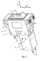
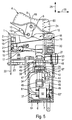
- the electrical switch is designed as a two-pole overcurrent protective switch 1 - hereinafter briefly: "protective switch 1".
- Its switch housing 2 which is made of insulating plastic, has a rectangular housing opening 3, which is inserted by a switching element in the form of a two-armed rocker switch 4.
- the rocker switch 4 In Fig. 1, the rocker switch 4 is in its on position, in which the circuits of the two phases of the circuit breaker 1 are closed.
- the rocker switch 4 can be pivoted between its switch-on position and a switch-off position that interrupts the circuits.
- Two resilient housing hooks 5, of which only three housing hooks 5 are visible in FIG. 1, are molded onto the two narrow sides of the switch housing 2. They are used to attach the circuit breaker 1 in a front panel, not shown here.
- the rocker switch 4 interacts with a switch lock or a switching mechanism for opening and closing switching contacts of the circuits and with a magnetic circuit for electromagnetic undervoltage release.
- the magnetic circuit is part of an undervoltage device 6, the device housing 7 of which is attached to the switch housing 2 in the installed position.
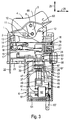
- the rocker switch 4 is pivotally mounted on a pivot axis 8 fixed to the housing (FIG. 3).
- a coupling cam 10 is attached to an end 9 of the rocker switch 4 facing the switching mechanism, which has a cam track running transversely to the pivoting plane of the rocker switch 4 11 penetrates a latch lever 12 (Fig. 3).
- the latching lever 12 is supported with a support lug 13 arranged at its one free end on a lever arm 14 of a two-armed trigger lever 15 which runs approximately vertically in the plane of the drawing.
- the trigger lever 15 is pivotally supported by means of an axle mount 16 on a housing axis running parallel to the pivot axis 8.
- the second lever arm of the release lever which is approximately at right angles to the latch arm 14, namely a release arm 17, is acted upon by an unillustrated bimetal in the event of overcurrent, as a result of which the release lever 15 is pivoted counterclockwise.
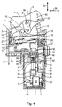
- the latch lever 12 is unlatched from the release lever 15 and thereby transfers the rocker switch 4 to its off position (this is done in principle in the sequence shown in FIGS. 4 and 5).
- the unlatched latching lever 12 ends the pressure on a contact spring 18, which swivels counterclockwise and thereby separates a switch contact 19 fastened at its free end from a fixed contact 20 (FIG. 4, FIG. 5) fixed in the switch housing 2.
- the circuit of the pole of the circuit breaker 1 shown in the drawing plane of FIGS. 3-5 is interrupted.
- the switch locks of both poles of the circuit breaker 1 are connected to one another or replaced by a single switch lock so that the circuits of both poles are always closed or interrupted at the same time.
- the contact spring 18 With its fastening end 21 facing away from the switching contact 19, the contact spring 18 is welded to a contact tongue 22.
- This contact tongue 22 is fixed in place in the switch housing 2 and projects beyond a bottom side 23 of the switch housing 2 in order to be connected in a known manner to the associated circuit.
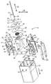
- the rocker switch 4 and the switch lock of the circuit breaker 1 are coupled to the magnetic circuit of the undervoltage device 6 via a fixing slide 24, which is shown particularly clearly in FIG. 2.
- the principle of operation of the coupling will be described in detail later.
- the fixing slide 24 can be moved or moved linearly in the assembled state within the switch housing 2 and the device housing 7.
- the displacement direction 25 runs in the direction its longitudinal extension.
- the fixing slide 24 is a plate-like component, the plate plane of which is spanned by the displacement direction 25 and a transverse direction 26 extending transversely thereto.
- the fixing slide 24 has a transverse shoulder 26 which, when the magnetic circuit opens, acts on the release arm 17 of the release lever 15 counterclockwise and thereby moves the switch lock into its contact opening position (FIG. 4).
- the circuit is interrupted in this contact opening position of the switch lock.
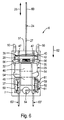
- the magnetic circuit contains a plate-shaped magnet armature 28 and a horseshoe-like, ie a U-shaped magnet core 29.
- the two U-legs of the magnet core 29 are connected to one another by a connecting yoke 30 and each have a pole face 31 at their free ends.
- the pole faces 31 make direct contact with a contact surface 32 of the magnet armature 28 facing them.
- the contact surface 32 and an opposing end face 33 of the magnet armature 28 facing the fixing slide 24 are arranged at right angles to the direction of displacement 25 of the fixing slide 24 in the assembled state.
- the contact surface 32 is held against the spring pressure of a helical spring 34 on the pole surfaces 31.
- the helical spring 34 arranged centrally between the two U-legs of the magnetic core 29 surrounds a centering mandrel 35 with its one axial spring end and acts on the contact surface 32 with its other axial spring end.
- the centering mandrel 35 is on the surface facing the magnet armature 28 approximately transversely to the direction of displacement 25 arranged support bearing 36 integrally formed.
- the support bearing 36 is supported in the assembled state on a bobbin 37 to be explained later.
- it In order to integrate the support bearing 36 in a particularly space-saving manner, it has two opposite bearing grooves 38, which each engage in a form-fitting manner in the assembled state of a U-leg of the magnetic core 29.
- a spring element in the form of an arched spring washer 39 is arranged between the fixing slide 24 and the magnet armature 28.
- the spring washer 39 tangents with its convex side a supporting edge 40 of the fixing slide 24 running in the transverse direction 26.
- the spring washer 39 is supported on the end face 33 of the magnet armature 28 with its two washer edges 41 running in the transverse direction 26.
- the spring washer 39 which is prestressed in the direction of the support edge 40, compensates for differences in the dimensions of the fixing slide 24 and the magnet armature 28 caused by production in the displacement direction 25.
- the magnet armature 28 is captively connected to the fixing slide 24 by a fixing pin 42 protruding beyond the supporting edge 40 in the direction of displacement 25.
- the fixing pin 42 which is T-shaped in cross section, has a transverse web 43 running in the transverse direction 26 at its free end facing the magnet armature 28.
- the fixing pin 42 passes through a central disk longitudinal slot 44 of the spring washer 39 and a cross-slot-shaped armature slot 45 of the magnet armature 28 in the direction of displacement 25.
- the armature slot 45 is formed by a first longitudinal slot and a shorter longitudinal slot crossing it.
- the crossbar 43 is passed through the longer longitudinal slot of the anchor slot 45.
- the fixing slide 24 is rotated by 90 °, so that the fixing pin 42 engages in the shorter longitudinal slot of the anchor slot 45.
- the crosspiece 43 engages behind the slot edge of the anchor slot 45 and is pressed against the contact surface 32 by the spring washer 39 pressing against the supporting edge 40.
- the fixing slide 24, the spring washer 39 and the magnet armature 28 are connected in a mechanically stable manner.
- the coil body 37 shown in two parts in FIG. 2 carries a coil 46 shown schematically in FIGS. 4-6.
- the two partial bodies 37 'of the coil body 37 each carry two guide webs 47 which run approximately in the direction of movement of the magnet armature 28.
- the guide webs 47 are in one piece molded onto the coil body 37 and, when the magnetic circuit is in the assembled state, protrude beyond the pole faces 31 in the direction of drop of the magnet armature 28.
- a guide web 47 of the partial body 37 ' is aligned in the transverse direction 26 with a guide web 47 of the second partial body 37'. These two aligned guide webs 47 flank the magnet armature 28 on both sides and thereby force a linear movement of the magnet armature 28 in the direction of displacement 25.
- a second pair of two guide webs 47 are integrally formed on the coil body 37 with a parallel spacing.
- the free ends of the guide webs 47 facing the fixing slide 24 have a stop lug 48 to limit the travel of the falling armature 28.
- the stop lugs 48 of the two guide webs 47 which are aligned with one another in the transverse direction 26 are directed towards one another and act on the end face 33 of the falling magnet armature 28 (FIG. 4).
- the plane of division of the coil former 37 is also its plane of symmetry, since the two partial bodies 37 'and 37' are of identical design.
- the U-plane of the magnetic core 29 lies approximately in the division plane of the coil former 37.
- the partial body 37 ' has an accommodating groove 49 with its opening facing the magnetic core 29.
- This receiving groove 49 is limited in the direction of displacement 25 by a plurality of groove webs 50.
- each partial body 37 ' two spring hooks 50 spaced apart from one another transversely to the plane of movement of the fixing slide 24 are formed on each partial body 37 '.
- a spring hook 50 of the first part body 37 ' is aligned in the transverse direction 26 with a spring hook 50 of the second part body 37'.
- the assembled bobbin 37 is inserted through an insertion opening 51 along an insertion direction 52 into the cuboid device housing 7 and locked with the device housing 7.
- the insides of the two side walls of the device housing 7 which run transversely to the plane of movement of the fixing slide 24 each have two mounting grooves 53, of which only the two mounting grooves 53 of one side wall are visible in FIG. 2 due to the perspective view.
- the two mounting grooves 53 of each side wall run at a parallel distance in the direction of insertion 52. They correspond to corresponding mounting webs 54 of the partial body 37 '.
- the plane of these guide webs 54 is spanned by the insertion direction 52 and the transverse direction 26. They allow simple assembly and exact positioning of the electromagnet in the device housing 7.
- the two side walls of the device housing 7, which run parallel to the plane of movement of the fixing slide 24, are penetrated by two latching holes 55 each. These latching holes 55 correspond to correspondingly designed latching lugs 56 (FIG. 2) formed on the partial bodies 37 '.
- the spring hooks 50 protrude beyond the insertion opening 51 of the device housing 7.
- the spring hooks 50 engage behind corresponding latching webs 57 in the region of the switch bottom side 23 (FIGS. 3-5).
- the insertion opening 51 of the device housing 7 is automatically sealed from the outside by a top wall 58 of the switch housing 2 arranged in the area of the switch bottom side 23.
- the fixing slide 24 connected to the magnet armature 28 projects beyond the insertion opening 51 of the device housing 7.
- the fixing slide 24 When assembling the device housing 7 on the circuit breaker 1, the fixing slide 24 passes through a wall opening of the top wall 58 in the direction of displacement 25 and is immersed in the switch housing 2.
- the fixing slide 24 is immersed in the rocker switch with a rod-shaped slide free end 60, which extends in the direction of displacement 25 beyond the contact shoulder 27 (FIGS. 3-5).
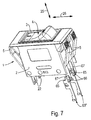
- the coil connections 61 of the coil 46 are connected in an electrically conductive manner via a bridge rectifier 62 to two device connection contacts 63 ′ or 63 ′′ of the undervoltage device 6 which are connected to the voltage to be monitored (FIG. 1, FIG. 7).
- a series resistor 64 is inserted into the electrical circuit between the bridge rectifier 62 and the device connection contacts 63 'or 63' '.
- the bridge rectifier 62 is captively fixed in the assembled state between a spring-elastic clamping arm 59 formed on the partial body 37 'and the partial body 37'.
- two device connection contacts 63 ′′ are arranged completely inside the device housing 7 (FIG. 4, FIG. 7).
- the undervoltage device 6 is electrically connected directly to connections of the circuit breaker 1.
- the free ends of the device connection contacts 63 ′′ facing the circuit breaker 1 are designed as flat contact tongues 65. These contact tongues 65 correspond to contact slots 66 of two switch connection contacts 67 running in the direction of displacement 25.
- the power supply line is connected to the two switch connection contacts 67 by means not shown here, in particular screwed on.
- the two contact slots 66 are dimensioned such that when the undervoltage device 6 is attached to the circuit breaker 1, the contact tongues 65 into the contact slots 66 intervene and be clamped by them with the necessary electrical contact pressure.
- the slide-free end 60 is decoupled from the rocker switch 4 and freely movable relative to the rocker switch 4 (FIG. 3).
- the fixing slide 24 coupled to the magnet armature 28 is displaced in the displacement direction 25 towards the actuation side 68 of the rocker switch 4 (FIG. 4).
- the abutment shoulder 27 of the fixing slide 24 acts on the release lever 15 counterclockwise, as a result of which the switching lock - as already described - is brought into the contact opening position.
- the switching rocker 4 which in this case pivots into its switched-off position with the aid of a torsion spring (not shown here), automatically acts on the fixing slide 24 with its actuating side 68 and moves it in the direction of displacement 25 towards the magnetic core 29 (FIG. 5).
- the magnetic circuit is therefore always automatically closed in the switched-off position of the rocker switch 4, even if the voltage required to hold the magnet armature 28 on the magnet core 29 is not yet present again at the device connection contacts 63 or 63 ′′.
- the electromagnet therefore only has to generate the required holding force for the magnet armature 28.
- the magnetic circuit is automatically opened when an attempt is made to move the rocker switch 4 into its switched-on position.
- the abutment shoulder 27 acts on the release lever 17, so that the switching lock is forced into its contact opening position.
- the rocker switch 4 can therefore not be moved to its switch-on position and the circuit breaker 1 cannot be switched on as long as the required voltage is not present again at the device connection contacts 63 'or 63' '.
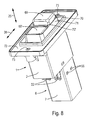
- FIG. 8 shows a further embodiment of the circuit breaker 1 with two push buttons 69, 69 'as a switching element. Components with the same function are given the same reference numerals in FIG. 8 as in FIGS. 1 to 7.
- the two push buttons 69, 69 'for switching the circuit can be moved in the displacement direction 25 and each positively penetrate a guide recess 70, 70'.
- the two guide recesses 70, 70 ' are part of a shaft-like guide attachment 71 molded onto the switch housing.
- the guide attachment 71 is surrounded by a mounting panel 72 which also forms a component of the switch housing 2 and which is penetrated by two circular mounting holes 73 in the direction of displacement 25.
- the mounting holes 73 serve to receive suitable fastening means, for example screws, with the aid of which the circuit breaker 1 is fixed in place at the mounting location.
- the mechanical coupling of the two push buttons 69, 69 'to one another for switching the circuit can in principle take place in the manner known from WO-A-9407255.
- the fixing slide 24, not shown in FIG. 8, is coupled to the push button 69 in such a way that in the switched-off position of the circuit breaker 1 or the push button 69, the fixing slide 24 assumes the position shown in FIG. 5.
- the slide-free end 60 preferably lies in a hood-like receiving opening of the push button 69 and is pressurized by the latter in the direction of the magnetic core 29.
- only a single push button is provided as a switching element and is coupled in a suitable manner to the fixing slide 24.
Landscapes
- Breakers (AREA)
- Tumbler Switches (AREA)
Priority Applications (1)
| Application Number | Priority Date | Filing Date | Title |
|---|---|---|---|
| DE29724577U DE29724577U1 (de) | 1997-04-17 | 1997-04-17 | Elektrischer Schalter mit Unterspannungsauslösung |
Applications Claiming Priority (2)
| Application Number | Priority Date | Filing Date | Title |
|---|---|---|---|
| DE29607027 | 1996-04-18 | ||
| DE29607027U | 1996-04-18 |
Publications (3)
| Publication Number | Publication Date |
|---|---|
| EP0802552A2 true EP0802552A2 (fr) | 1997-10-22 |
| EP0802552A3 EP0802552A3 (fr) | 1999-03-10 |
| EP0802552B1 EP0802552B1 (fr) | 2001-11-21 |
Family
ID=8022750
Family Applications (1)
| Application Number | Title | Priority Date | Filing Date |
|---|---|---|---|
| EP97106350A Expired - Lifetime EP0802552B1 (fr) | 1996-04-18 | 1997-04-17 | Interrupteur électrique à déclenchement par manque de tension |
Country Status (4)
| Country | Link |
|---|---|
| US (1) | US5834996A (fr) |
| EP (1) | EP0802552B1 (fr) |
| JP (1) | JP3754796B2 (fr) |
| DE (1) | DE59705433D1 (fr) |
Cited By (3)
| Publication number | Priority date | Publication date | Assignee | Title |
|---|---|---|---|---|
| DE19919331A1 (de) * | 1999-04-28 | 2000-11-02 | Ellenberger & Poensgen | Unterspannungsauslöser |
| WO2010145757A1 (fr) * | 2009-06-19 | 2010-12-23 | Ellenberger & Poensgen Gmbh | Procédé de commande du déclenchement d'un disjoncteur de protection électronique |
| DE102009025513A1 (de) | 2009-06-19 | 2010-12-30 | Ellenberger & Poensgen Gmbh | Elektronischer Schutzschalter |
Families Citing this family (5)
| Publication number | Priority date | Publication date | Assignee | Title |
|---|---|---|---|---|
| US6613995B1 (en) | 2002-01-04 | 2003-09-02 | Reliance Controls Corporation | Switch having stabilizing protrusions to facilitate mounting thereof |
| US8087977B2 (en) | 2005-05-13 | 2012-01-03 | Black & Decker Inc. | Angle grinder |
| EP2462608B1 (fr) * | 2009-08-04 | 2013-03-27 | Abb Ab | Contacteur basse-tension |
| US10818450B2 (en) | 2017-06-14 | 2020-10-27 | Black & Decker Inc. | Paddle switch |
| USD938369S1 (en) * | 2019-10-21 | 2021-12-14 | Ellenberger & Poensgen Gmbh | Combined electrical switch with mounting plate |
Family Cites Families (12)
| Publication number | Priority date | Publication date | Assignee | Title |
|---|---|---|---|---|
| US4019097A (en) * | 1974-12-10 | 1977-04-19 | Westinghouse Electric Corporation | Circuit breaker with solid state passive overcurrent sensing device |
| US4034266A (en) * | 1975-08-29 | 1977-07-05 | Westinghouse Electric Corporation | Electric wall receptacle with ground fault protection |
| CH614069A5 (fr) * | 1977-03-31 | 1979-10-31 | Weber Ag Fab Elektro | |
| DE2928277C2 (de) * | 1979-07-13 | 1983-12-01 | Ellenberger & Poensgen Gmbh, 8503 Altdorf | Kombinierbarer zweipoliger Überstromschutzschalter |
| DE3114717C2 (de) * | 1981-04-11 | 1987-04-30 | Licentia Patent-Verwaltungs-Gmbh, 6000 Frankfurt | Unterspannungsauslöser für einen Leitungsschutzschalter |
| DE3424089A1 (de) * | 1983-08-19 | 1985-03-07 | Weber AG Fabrik elektrotechnischer Artikel und Apparate, Emmenbrücke | Druckknopfbetaetigter ueberstromschalter |
| DE3340250A1 (de) * | 1983-11-08 | 1985-05-15 | Heinrich Kopp Gmbh & Co Kg, 8756 Kahl | Fehlerstromschutzschalter(-teil) mit unterspannungsausloesung |
| DE4003744A1 (de) * | 1990-02-08 | 1991-08-14 | Klinger & Born Gmbh | Drehschalter |
| CH680174A5 (fr) * | 1990-05-23 | 1992-06-30 | Weber Ag | |
| EP0660965B1 (fr) * | 1992-09-19 | 1997-04-09 | Ellenberger & Poensgen GmbH | Commutateur de securite actionne par bouton |
| DE59402333D1 (de) * | 1993-03-17 | 1997-05-15 | Ellenberger & Poensgen | Geräteschalter mit integriertem Überstromschutz |
| DE4341214C2 (de) * | 1993-12-03 | 1996-11-07 | Kloeckner Moeller Gmbh | Auslöseeinheit für Leistungs- oder Schutzschalter |
-
1997
- 1997-04-15 US US08/843,398 patent/US5834996A/en not_active Expired - Lifetime
- 1997-04-17 DE DE59705433T patent/DE59705433D1/de not_active Expired - Lifetime
- 1997-04-17 EP EP97106350A patent/EP0802552B1/fr not_active Expired - Lifetime
- 1997-04-18 JP JP10212397A patent/JP3754796B2/ja not_active Expired - Fee Related
Cited By (3)
| Publication number | Priority date | Publication date | Assignee | Title |
|---|---|---|---|---|
| DE19919331A1 (de) * | 1999-04-28 | 2000-11-02 | Ellenberger & Poensgen | Unterspannungsauslöser |
| WO2010145757A1 (fr) * | 2009-06-19 | 2010-12-23 | Ellenberger & Poensgen Gmbh | Procédé de commande du déclenchement d'un disjoncteur de protection électronique |
| DE102009025513A1 (de) | 2009-06-19 | 2010-12-30 | Ellenberger & Poensgen Gmbh | Elektronischer Schutzschalter |
Also Published As
| Publication number | Publication date |
|---|---|
| JP3754796B2 (ja) | 2006-03-15 |
| US5834996A (en) | 1998-11-10 |
| EP0802552A3 (fr) | 1999-03-10 |
| JPH1040779A (ja) | 1998-02-13 |
| DE59705433D1 (de) | 2002-01-03 |
| EP0802552B1 (fr) | 2001-11-21 |
Similar Documents
| Publication | Publication Date | Title |
|---|---|---|
| DE3834980C2 (de) | Anschlußanordnung für einen Schalter mit Formgehäuse | |
| EP0317660B1 (fr) | Contacteur | |
| EP0563774A2 (fr) | Disjoncteur de protection avec commande à distance | |
| DE1256300B (de) | Schaltschuetz | |
| EP0033841B1 (fr) | Relais | |
| EP0185107A1 (fr) | Disjoncteur de protection pour moteurs | |
| DE3713537A1 (de) | Umkehr-schaltvorrichtung mit ueberstromschutz | |
| EP0303965B1 (fr) | Appareil de commutation électrique | |
| DE3880659T2 (de) | Schutzgerät für elektrische Anlagen. | |
| EP0802552B1 (fr) | Interrupteur électrique à déclenchement par manque de tension | |
| DE69218025T2 (de) | Elektromechanisches Schaltgerät mit frontalem Zusatzbauteil | |
| EP1074030A1 (fr) | Appareil de commutation comportant un module a chambre de coupure | |
| DE4423277B4 (de) | Leistungsschalter mit gemeinsamem Auslösemechanismus | |
| DE3539976A1 (de) | Abschaltvorrichtung mit fernsteuerung der oeffnung und schliessung ihrer kreise | |
| DE1465705B1 (de) | Elektrischer Schnappschalter mit Drueckerhebel | |
| DE3851093T2 (de) | Mehrpoliger Schalter. | |
| DE4233918B4 (de) | Elektrischer Schalter mit Stromüberwachung | |
| EP0036432B2 (fr) | Contacteur, en particulier un contacteur de puissance ou de commande ou de mise en marche | |
| EP2387059A2 (fr) | Commutateur d'installation électrique avec un dispositif de fixation rapide | |
| EP0188482B1 (fr) | Verrou de commutation | |
| DE721862C (de) | Selbstschalter, insbesondere Trennschutzschalter | |
| DE1588754B2 (de) | Elektrischer Selbstschalter | |
| DE69509704T2 (de) | Schaltschutz mit Rasteinrichtung für Schienenmontage | |
| DE3734396A1 (de) | Elektrisches schaltgeraet | |
| DE19653266A1 (de) | Installationsschaltgerät |
Legal Events
| Date | Code | Title | Description |
|---|---|---|---|
| PUAI | Public reference made under article 153(3) epc to a published international application that has entered the european phase |
Free format text: ORIGINAL CODE: 0009012 |
|
| AK | Designated contracting states |
Kind code of ref document: A2 Designated state(s): CH DE FR GB IT LI |
|
| PUAL | Search report despatched |
Free format text: ORIGINAL CODE: 0009013 |
|
| AK | Designated contracting states |
Kind code of ref document: A3 Designated state(s): CH DE FR GB IT LI |
|
| 17P | Request for examination filed |
Effective date: 19990408 |
|
| GRAG | Despatch of communication of intention to grant |
Free format text: ORIGINAL CODE: EPIDOS AGRA |
|
| 17Q | First examination report despatched |
Effective date: 20010531 |
|
| GRAG | Despatch of communication of intention to grant |
Free format text: ORIGINAL CODE: EPIDOS AGRA |
|
| GRAH | Despatch of communication of intention to grant a patent |
Free format text: ORIGINAL CODE: EPIDOS IGRA |
|
| GRAH | Despatch of communication of intention to grant a patent |
Free format text: ORIGINAL CODE: EPIDOS IGRA |
|
| GRAA | (expected) grant |
Free format text: ORIGINAL CODE: 0009210 |
|
| AK | Designated contracting states |
Kind code of ref document: B1 Designated state(s): CH DE FR GB IT LI |
|
| REG | Reference to a national code |
Ref country code: CH Ref legal event code: EP |
|
| REG | Reference to a national code |
Ref country code: CH Ref legal event code: NV Representative=s name: E. BLUM & CO. PATENTANWAELTE |
|
| REG | Reference to a national code |
Ref country code: GB Ref legal event code: IF02 |
|
| REF | Corresponds to: |
Ref document number: 59705433 Country of ref document: DE Date of ref document: 20020103 |
|
| GBT | Gb: translation of ep patent filed (gb section 77(6)(a)/1977) |
Effective date: 20020216 |
|
| ET | Fr: translation filed | ||
| PLBE | No opposition filed within time limit |
Free format text: ORIGINAL CODE: 0009261 |
|
| STAA | Information on the status of an ep patent application or granted ep patent |
Free format text: STATUS: NO OPPOSITION FILED WITHIN TIME LIMIT |
|
| 26N | No opposition filed | ||
| REG | Reference to a national code |
Ref country code: CH Ref legal event code: PFA Owner name: ELLENBERGER & POENSGEN GMBH Free format text: ELLENBERGER & POENSGEN GMBH#INDUSTRIESTRASSE 2-8#D-90518 ALTDORF (DE) -TRANSFER TO- ELLENBERGER & POENSGEN GMBH#INDUSTRIESTRASSE 2-8#D-90518 ALTDORF (DE) |
|
| REG | Reference to a national code |
Ref country code: FR Ref legal event code: PLFP Year of fee payment: 19 |
|
| PGFP | Annual fee paid to national office [announced via postgrant information from national office to epo] |
Ref country code: GB Payment date: 20150423 Year of fee payment: 19 Ref country code: CH Payment date: 20150422 Year of fee payment: 19 Ref country code: DE Payment date: 20150428 Year of fee payment: 19 |
|
| PGFP | Annual fee paid to national office [announced via postgrant information from national office to epo] |
Ref country code: IT Payment date: 20150423 Year of fee payment: 19 Ref country code: FR Payment date: 20150422 Year of fee payment: 19 |
|
| REG | Reference to a national code |
Ref country code: DE Ref legal event code: R119 Ref document number: 59705433 Country of ref document: DE |
|
| REG | Reference to a national code |
Ref country code: CH Ref legal event code: PL |
|
| GBPC | Gb: european patent ceased through non-payment of renewal fee |
Effective date: 20160417 |
|
| REG | Reference to a national code |
Ref country code: FR Ref legal event code: ST Effective date: 20161230 |
|
| PG25 | Lapsed in a contracting state [announced via postgrant information from national office to epo] |
Ref country code: LI Free format text: LAPSE BECAUSE OF NON-PAYMENT OF DUE FEES Effective date: 20160430 Ref country code: FR Free format text: LAPSE BECAUSE OF NON-PAYMENT OF DUE FEES Effective date: 20160502 Ref country code: GB Free format text: LAPSE BECAUSE OF NON-PAYMENT OF DUE FEES Effective date: 20160417 Ref country code: CH Free format text: LAPSE BECAUSE OF NON-PAYMENT OF DUE FEES Effective date: 20160430 Ref country code: DE Free format text: LAPSE BECAUSE OF NON-PAYMENT OF DUE FEES Effective date: 20161101 |
|
| PG25 | Lapsed in a contracting state [announced via postgrant information from national office to epo] |
Ref country code: IT Free format text: LAPSE BECAUSE OF NON-PAYMENT OF DUE FEES Effective date: 20160417 |