EP0563774A2 - Disjoncteur de protection avec commande à distance - Google Patents
Disjoncteur de protection avec commande à distance Download PDFInfo
- Publication number
- EP0563774A2 EP0563774A2 EP93104852A EP93104852A EP0563774A2 EP 0563774 A2 EP0563774 A2 EP 0563774A2 EP 93104852 A EP93104852 A EP 93104852A EP 93104852 A EP93104852 A EP 93104852A EP 0563774 A2 EP0563774 A2 EP 0563774A2
- Authority
- EP
- European Patent Office
- Prior art keywords
- switch
- lever
- drive
- switching
- contact
- Prior art date
- Legal status (The legal status is an assumption and is not a legal conclusion. Google has not performed a legal analysis and makes no representation as to the accuracy of the status listed.)
- Granted
Links
- 230000001681 protective effect Effects 0.000 title description 2
- 230000008878 coupling Effects 0.000 claims description 33
- 238000010168 coupling process Methods 0.000 claims description 33
- 238000005859 coupling reaction Methods 0.000 claims description 33
- 210000000629 knee joint Anatomy 0.000 claims description 13
- 230000005405 multipole Effects 0.000 claims description 7
- 238000005520 cutting process Methods 0.000 claims description 4
- 230000001419 dependent effect Effects 0.000 claims description 3
- 238000005192 partition Methods 0.000 claims description 3
- 230000011664 signaling Effects 0.000 claims description 3
- 210000003127 knee Anatomy 0.000 claims 1
- 230000007246 mechanism Effects 0.000 abstract description 11
- 210000002414 leg Anatomy 0.000 description 30
- 238000010276 construction Methods 0.000 description 6
- 239000004020 conductor Substances 0.000 description 5
- 230000000694 effects Effects 0.000 description 5
- 230000005540 biological transmission Effects 0.000 description 4
- 238000010586 diagram Methods 0.000 description 4
- 230000005520 electrodynamics Effects 0.000 description 4
- 230000006870 function Effects 0.000 description 4
- 239000002184 metal Substances 0.000 description 4
- 229910052751 metal Inorganic materials 0.000 description 4
- 238000012806 monitoring device Methods 0.000 description 4
- 230000001960 triggered effect Effects 0.000 description 4
- 230000004907 flux Effects 0.000 description 3
- 230000035945 sensitivity Effects 0.000 description 3
- 230000000712 assembly Effects 0.000 description 2
- 238000000429 assembly Methods 0.000 description 2
- 238000009434 installation Methods 0.000 description 2
- 238000009413 insulation Methods 0.000 description 2
- 238000004519 manufacturing process Methods 0.000 description 2
- 238000000034 method Methods 0.000 description 2
- 230000008569 process Effects 0.000 description 2
- 238000010791 quenching Methods 0.000 description 2
- 230000000171 quenching effect Effects 0.000 description 2
- 230000009467 reduction Effects 0.000 description 2
- 229910000531 Co alloy Inorganic materials 0.000 description 1
- 230000009471 action Effects 0.000 description 1
- 238000005452 bending Methods 0.000 description 1
- 230000008901 benefit Effects 0.000 description 1
- 230000008859 change Effects 0.000 description 1
- 230000007423 decrease Effects 0.000 description 1
- 230000007547 defect Effects 0.000 description 1
- 230000002950 deficient Effects 0.000 description 1
- 238000006073 displacement reaction Methods 0.000 description 1
- 238000005265 energy consumption Methods 0.000 description 1
- 230000002349 favourable effect Effects 0.000 description 1
- 230000003993 interaction Effects 0.000 description 1
- 230000002045 lasting effect Effects 0.000 description 1
- 239000000696 magnetic material Substances 0.000 description 1
- 230000014759 maintenance of location Effects 0.000 description 1
- 230000007257 malfunction Effects 0.000 description 1
- 230000000149 penetrating effect Effects 0.000 description 1
- 230000008439 repair process Effects 0.000 description 1
- 239000000523 sample Substances 0.000 description 1
- 230000000007 visual effect Effects 0.000 description 1
- 238000004804 winding Methods 0.000 description 1
Images


Classifications
-
- H—ELECTRICITY
- H01—ELECTRIC ELEMENTS
- H01H—ELECTRIC SWITCHES; RELAYS; SELECTORS; EMERGENCY PROTECTIVE DEVICES
- H01H71/00—Details of the protective switches or relays covered by groups H01H73/00 - H01H83/00
- H01H71/10—Operating or release mechanisms
- H01H71/66—Power reset mechanisms
- H01H71/68—Power reset mechanisms actuated by electromagnet
-
- H—ELECTRICITY
- H01—ELECTRIC ELEMENTS
- H01H—ELECTRIC SWITCHES; RELAYS; SELECTORS; EMERGENCY PROTECTIVE DEVICES
- H01H71/00—Details of the protective switches or relays covered by groups H01H73/00 - H01H83/00
- H01H71/10—Operating or release mechanisms
- H01H71/12—Automatic release mechanisms with or without manual release
- H01H71/46—Automatic release mechanisms with or without manual release having means for operating auxiliary contacts additional to the main contacts
-
- H—ELECTRICITY
- H01—ELECTRIC ELEMENTS
- H01H—ELECTRIC SWITCHES; RELAYS; SELECTORS; EMERGENCY PROTECTIVE DEVICES
- H01H71/00—Details of the protective switches or relays covered by groups H01H73/00 - H01H83/00
- H01H71/04—Means for indicating condition of the switching device
- H01H2071/048—Means for indicating condition of the switching device containing non-mechanical switch position sensor, e.g. HALL sensor
-
- H—ELECTRICITY
- H01—ELECTRIC ELEMENTS
- H01H—ELECTRIC SWITCHES; RELAYS; SELECTORS; EMERGENCY PROTECTIVE DEVICES
- H01H71/00—Details of the protective switches or relays covered by groups H01H73/00 - H01H83/00
- H01H71/10—Operating or release mechanisms
- H01H71/12—Automatic release mechanisms with or without manual release
- H01H71/46—Automatic release mechanisms with or without manual release having means for operating auxiliary contacts additional to the main contacts
- H01H2071/467—Automatic release mechanisms with or without manual release having means for operating auxiliary contacts additional to the main contacts with history indication, e.g. of trip and/or kind of trip, number of short circuits etc.
-
- H—ELECTRICITY
- H01—ELECTRIC ELEMENTS
- H01H—ELECTRIC SWITCHES; RELAYS; SELECTORS; EMERGENCY PROTECTIVE DEVICES
- H01H47/00—Circuit arrangements not adapted to a particular application of the relay and designed to obtain desired operating characteristics or to provide energising current
- H01H47/22—Circuit arrangements not adapted to a particular application of the relay and designed to obtain desired operating characteristics or to provide energising current for supplying energising current for relay coil
- H01H47/226—Circuit arrangements not adapted to a particular application of the relay and designed to obtain desired operating characteristics or to provide energising current for supplying energising current for relay coil for bistable relays
-
- H—ELECTRICITY
- H01—ELECTRIC ELEMENTS
- H01H—ELECTRIC SWITCHES; RELAYS; SELECTORS; EMERGENCY PROTECTIVE DEVICES
- H01H50/00—Details of electromagnetic relays
- H01H50/10—Electromagnetic or electrostatic shielding
-
- H—ELECTRICITY
- H01—ELECTRIC ELEMENTS
- H01H—ELECTRIC SWITCHES; RELAYS; SELECTORS; EMERGENCY PROTECTIVE DEVICES
- H01H51/00—Electromagnetic relays
- H01H51/22—Polarised relays
- H01H51/2209—Polarised relays with rectilinearly movable armature
-
- H—ELECTRICITY
- H01—ELECTRIC ELEMENTS
- H01H—ELECTRIC SWITCHES; RELAYS; SELECTORS; EMERGENCY PROTECTIVE DEVICES
- H01H71/00—Details of the protective switches or relays covered by groups H01H73/00 - H01H83/00
- H01H71/04—Means for indicating condition of the switching device
-
- H—ELECTRICITY
- H01—ELECTRIC ELEMENTS
- H01H—ELECTRIC SWITCHES; RELAYS; SELECTORS; EMERGENCY PROTECTIVE DEVICES
- H01H71/00—Details of the protective switches or relays covered by groups H01H73/00 - H01H83/00
- H01H71/10—Operating or release mechanisms
- H01H71/12—Automatic release mechanisms with or without manual release
- H01H71/14—Electrothermal mechanisms
- H01H71/16—Electrothermal mechanisms with bimetal element
-
- H—ELECTRICITY
- H01—ELECTRIC ELEMENTS
- H01H—ELECTRIC SWITCHES; RELAYS; SELECTORS; EMERGENCY PROTECTIVE DEVICES
- H01H71/00—Details of the protective switches or relays covered by groups H01H73/00 - H01H83/00
- H01H71/10—Operating or release mechanisms
- H01H71/12—Automatic release mechanisms with or without manual release
- H01H71/42—Induction-motor, induced-current, or electrodynamic release mechanisms
- H01H71/43—Electrodynamic release mechanisms
Definitions
- the invention relates to a remotely controllable circuit breaker with the features of the preamble of claim 1.
- circuit breakers are used, for example, in the on-board networks of land vehicles, aircraft or ships. They are increasingly replacing conventional on-board circuit breakers in which the power lines are routed from the power source to the dashboard in the cockpit and from there to the electrical consumer.
- Remote-controlled circuit breakers can be arranged directly on the electrical consumer, so that the power lines are led directly from the power source to the electrical consumer, without going through the control panel.
- the circuit breaker is then switched on and off by an external remote switch located in the control panel. The external remote switch is only connected to the circuit breaker by control lines.
- Such an arrangement of remotely controllable circuit breakers reduces the cable weight in vehicle electrical systems and therefore also reduces the costs for the cabling.
- the cabling itself is simplified and saves space.
- the construction of the control panel is also simplified, since it only comes from the control device, e.g. consists of the external remote switches.
- the control device can also be a computer. With the help of the control device, the circuit breaker can be switched on and off, the switching status of the contacts can be displayed and the tripping by overcurrent can be displayed.
- control electronics acting on a switching drive are integrated.
- a thermal release element and a mechanical switch lock for closing and interrupting the circuit are present in the circuit breaker.
- the switching drive or the thermal release element cause the switching movements of the key switch.
- the invention is based on the object of designing a remotely controllable circuit breaker in such a way that it is simplified in structure with few components and thus reduces its susceptibility to faults. This object is achieved by the combination of features of claim 1.
- This switch drive also fulfills the requirements for EMC (electromagnetic compatibility) in vehicle electrical systems. At the same time, it supports stable operating positions of the circuit breaker. This switching drive ensures high holding, pushing and pulling forces with low control energy consumption. This has a cost-saving effect, while the performance of the circuit breaker is increased. A simple construction of the mechanics is thus possible for reliable closing and interruption of the circuit. This has a favorable effect on the dimensioning of the circuit breaker housing and on the cost of the circuit breaker.
- the auxiliary switch acts as a link between the control electronics and the switching drive on the one hand and the mechanics of the circuit breaker on the other hand and uses the switching movement of the switch lock after the bimetallic release of the circuit breaker to trigger the external remote switch without additional components.
- the remote switch acts on the switching drive via the control electronics so that it can be latched again with the switching lock. In this way, a defined switch-off position of the circuit breaker is achieved in a simple automatic sequence.
- Coupling the key switch with the control electronics enables a reduction in the number of components for triggering the various operating functions. This is the prerequisite for a simple construction of the circuit breaker. This reduces its cost and increases its reliability.
- Claims 2 and 3 support the orderly and automatic functional sequence of the circuit breaker.
- the electrical signal of the additional switch for the control electronics can be used to trigger certain functions of the circuit breaker.
- the functional sequence is thus dependent on the switching position of the switching drive. This further contributes to the orderly functioning of the circuit breaker.
- the switching position of the switching drive can also be easily determined by the electrical signal of the additional switch e.g. be displayed optically or acoustically.
- the additional switch according to claim 5 causes by its connection to the control electronics in a technically simple manner, the release for reclosing the circuit breaker.
- the restart is thus dependent on the switching position of the shift actuator, which continues to support the orderly functional sequence.
- Claim 6 relates to a preferred embodiment of the switch lock. This embodiment supports the simple structure of the circuit breaker and an effective power transmission of the rotary movements of the levers for the switch positions of the key switch. This guarantees reliable opening and closing of the circuit.
- the mechanical movements of the switch lock are linked to the switch position of the auxiliary switch.
- the operating position of the key switch can be displayed without additional components. Stable switch positions of the switch lock ensure reliable switching of the auxiliary switch and thus prevent malfunction of the circuit breaker.
- Claim 7 allows for a corresponding arrangement of latch lever and auxiliary switch to switch it with little effort.
- the displacement and / or rotary movement of the latching lever is used.
- the auxiliary switch can advantageously also be used as a rotation limit stop.
- Claim 8 facilitates the switching of the auxiliary switch by means of the latch lever.
- Claim 9 relates to a measure for opening the circuit in the event of overcurrent.
- the bimetal is coupled to the switch position of the auxiliary switch via the latching lever and enables the bimetal release to be displayed without additional components.
- the circuit breaker is switched off by the unlatching that takes place during the bimetallic release.
- the switch rod attached according to claim 10 enables good power transmission to the switch lock of the circuit breaker during the switching process of the switch drive.
- Claim 11 relates to a measure for mechanical coupling between the switching drive and switch lock.
- Claim 12 enables a very effective power transmission between the drive lever and the latching lever of the key switch.
- the geometric design of the drive lever according to claim 13 facilitates switching of the additional switch.
- the components arranged in the circuit breaker according to claim 15 create the conditions for a low installation height of the circuit breaker.
- the circuit breaker therefore only takes up a small amount of space on site. Furthermore, the assembly of the individual components within the circuit breaker is facilitated.
- a circuit breaker according to claim 16 is also suitable for other measurands other than overcurrent.
- the signal applied to the sensor replaces the signal of the auxiliary switch when it is switched as a result of the bimetallic release and acts in the same way on the control electronics.
- control electronics enables its convenient and space-saving installation in the circuit breaker.
- the connecting lines to the auxiliary switch, additional switch and switching drive are thus kept short.
- the control electronics can be in the event of a defect exchange easily. This also reduces repair times at the circuit breaker.
- a circuit breaker according to claim 18 takes into account external connection options to the circuit breaker via its terminal block, e.g. for measuring purposes. This makes it easy to check various functions of the circuit breaker.
- Claims 19 and 20 relate to a simple possibility of signaling the switching position of the switching lock via a display device which can be connected to the connection block.
- the remote switch can also be connected to the control electronics in a simple manner. A defective remote switch can be replaced without any special assembly work. In addition, different types of remote switches can be used without changing the circuit breaker design.
- a single-pole circuit breaker according to claim 22 can be easily used as a multi-pole circuit breaker, e.g. suitable for three-phase current.
- a pre-assembly of the circuit breaker according to the number of phases is not necessary.
- the design of the single-pole circuit breaker is not changed for different phase numbers. This means reduced manufacturing and logistics costs.
- Claim 23 relates to a further possibility to couple several single-pole circuit breakers to a multi-pole circuit breaker. As a result, the connection blocks can be saved except for one.
- Claim 24 avoids sources of electrical danger, e.g. Risk of short circuit and ensures safe operation of the single-pole as well as the multi-pole circuit breaker.
- Claim 25 relates to an advantageous measure for coupling a plurality of single-pole circuit breakers to a multi-pole circuit breaker. With this multi-pole circuit breaker, switching drives can be saved except for one and reduce the costs of this circuit breaker.
- Fig. 1 the assemblies contained in the circuit breaker 1 and their mutual coupling are shown schematically. These assemblies are control electronics 2, an electromagnetic switch drive 3, a switch lock 4, a bimetal 5, an auxiliary switch 6 and an additional switch 7.
- the switch position of the auxiliary switch 6 is clearly given by the switch position of the switch lock 4.
- the switching position of the additional switch 7 is clearly given by the switching position of the switching drive 3.
- the circuit inside the circuit breaker 1 is interrupted or closed.
- the key switch 4 is opened either by bimetallic release or by actuating the switching drive 3.
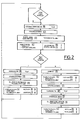
- the functional sequence of the circuit breaker 1 is shown in more detail in FIG. 2.
- the control electronics 2 generate a current pulse in order to transfer the electromagnetic switching drive 3 into its switched-on position.
- the switching drive 3 and the switching mechanism 4 are in this case interlocked with one another, so that the switching mechanism 4 is moved into its closed position. This closes the circuit.
- the switch lock 4 is closed, the auxiliary switch 6 is in the switching position I.
- the switching drive 3 is in the switched-on position, the additional switch 7 is in the switching position I.
- the circuit can now be interrupted either by bimetallic release or by the user via the remote switch 8.
- the bimetal 5 acts on the switching lock 4 in order to unlatch the latter from the switching drive 3 and to move it into its open position.
- the circuit In the open position of the key switch 4, the circuit is interrupted.
- the switching mechanism 4 switches the auxiliary switch 6. It is therefore in switch position II.
- the switching drive 3 is not actuated, so that the additional switch 7 remains in switch position I.
- the new switching position of the auxiliary switch 6 causes a signal via the control electronics 2 to switch off the remote switch 8.
- the switched-off remote switch 8 in turn causes a current pulse in the control electronics 2 in order to now also move the switching drive 3 into its switched-off position.
- the switching drive 3 After reaching its switch-off position, the switching drive 3 is latched again with the switching mechanism 4, which is still in its open position. In its switched-off position, the switching drive 3 switches the additional switch 7, so that it is now in switching position II. The switch position of the switch lock 4 is unchanged, so that the auxiliary switch 6 remains in switch position II.
- the new combination of the switch positions of auxiliary switch 6 and auxiliary switch 7 enables the user to switch on the circuit breaker 1 again via the remote switch 8. With this automatic sequence, the same starting position of the various modules for switching the circuit breaker 1 back on is achieved, as is also achieved after the user has switched off the circuit breaker 1 externally.
- the remote switch 8 When the protective switch 1 is switched off externally by the user, the remote switch 8 is first switched off.
- the control electronics 2 then generate the current pulse already mentioned in order to transfer the switching drive 3 from its switched-on position to its switched-off position. Since the switching drive 3 and switching mechanism 4 are interlocked, the switching mechanism 4 is moved into its open position.
- the auxiliary switch 6 and the additional switch 7 are therefore each in switch position II. This combination of the switch positions of auxiliary switch 6 and additional switch 7 already mentioned releases the circuit breaker 1 for its reclosure by the user via the external remote switch 8.
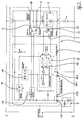
- the internal control electronics 2 of the single-pole circuit breaker 1 are explained on the basis of the block diagram in FIG. 3. It is designed for both direct voltage (e.g. 28 volts) and alternating voltage (e.g. 115 volts). This is achieved by means of a voltage limitation 9 and an internal power supply 10.
- the additional switch 7 is coupled to the switching position of a drive lever 11 (FIG. 6) connected to the switching drive 3.
- the auxiliary switch 6 is coupled to the switching position of a contact lever 12 via a latch lever 13.
- Auxiliary switch 6 and additional switch 7 are connected via signal lines to inputs of a leading edge control 14 arranged within the control electronics 2.
- the outputs of the phase gating control 14 are connected to the remote switch 8 via an input 15 of the control electronics 2 denoted by “1”.
- the input 15 is connected to a connecting line 16 (FIG. 15).
- the remote switch 8 is e.g. arranged in the cockpit of an aircraft.
- the "bistable switching coil” of the block diagram corresponds to the switching drive 3.
- the switching drive 3 receives its control energy via a pulse generator 17 and a full transistor bridge 18 connected to it.
- a status indicator 19 shows the respective switching position of the contact lever 12 as part of the switch lock 4.
- a microswitch serves as a status indicator 19. It is arranged in the plane of the drawing from FIGS. 6 to 8 behind the auxiliary switch 6 and is therefore not shown there. Like the auxiliary switch 6, it is switched by means of the latch lever 13.
- the status indicator 19 is connected to three connecting lines 16 (FIG. 15).
- a display device can be connected to the status indicator 19 by means of the connection sockets 20 of a connection block 21. This can e.g. be displayed optically or acoustically whether the circuit is open or closed.
- the control electronics 2 react to an external switching signal (remote switch 8) and an internal switching signal.
- the internal switching signal is triggered by bimetal 5 or by a sensor.
- a combination of sensor and bimetal 5 is also conceivable.
- the sensor is electrically connected in parallel to the auxiliary switch 6.
- the remote switch 8 is turned on, for example.
- the control electronics 2 thereby receive an external switching signal at the input 15.
- the external switching signal generates an approximately via the pulse generator 17 and the full transistor bridge 18 30 ms current pulse for the electromagnetic switching drive 3.
- the drive lever 11 is rotated into its switched-on position, the contact lever 12 reaches its contact position (FIG. 6). If the remote switch 8 is switched off, the switching drive 3 receives an opposite current pulse, likewise lasting about 30 ms. Drive lever 11 and contact lever 12 are transferred to their switch-off position (FIG. 7).
- auxiliary switch 6 causes, via the phase control 14, that no signal is present at the pulse generator 17.
- the switching drive 3 again receives a current pulse for transferring the drive lever 11 into its switched-on position (FIG. 6).
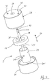
- the switching drive 3 consists essentially of an annular permanent magnet 22, a hollow cylindrical armature 23, the switching rod 25 penetrating through the armature 23 in the axial direction 24, and two housing halves.
- the permanent magnet 22 consists, for example, of an alloy of cobalt and rare earths.
- the two housing halves are the cylindrical pot bottom 26 and the likewise cylindrical pot lid 27.
- the mutually facing annular end faces of the pot bottom 26 and the pot lid 27 are in the Final assembly condition locked together (Fig. 5).
- the circular outer surface 28 of the pot lid 27 contains a central rod guide bore 29 and two strand bores 30, 31.
- the circular outer surface 28 is made in one piece with the remaining area of the pot lid 27. This avoids air gaps to improve the magnetic force effect. The same applies to pot bottom 26.
- the armature 23 is firmly connected to the shift rod 25 by two fixing pins 37 (FIG. 5).
- the fixing pins 37 engage in a form-fitting manner in two grooves 38 (FIG. 4) formed on the shift rod 25 and in corresponding pin bores 39 of the armature 23.
- An adjustment slot 40 extending in the axial direction 24 is formed in the end region of the switching rod 25 facing the pot lid 27.
- the adjustment slot 40 runs transversely to the axial direction 24 in accordance with the diameter of the shift rod 25. By means of the adjustment slot 40, the shift rod 25 can be simply rotated mechanically for adjustment purposes.
- the flattening 41 also serves to transmit an actuating torque.
- the end region of the switching rod 25 facing the pot bottom 26 is designed as a rod thread 42 (FIG.
- the coupling member 43 like the drive lever 11 (FIG. 6), contains a bore which is penetrated by a coupling axis 45 running in the depth direction 44 (FIG. 13).
- the structure of the drive lever 11 and the parts connected to it are explained in more detail below (FIG. 13).
- a truncated cone 46 is integrally formed on the pot lid 27 inwards.
- the truncated cone 46 tapers in the direction of the opposite pot bottom 26 and is centrally penetrated by the rod guide bore 29 in the axial direction 24.
- the armature 23 has on its end facing the truncated cone 46 a conical recess adapted to the truncated cone 46. The same applies analogously to the truncated cone 46 ′ of the pot base 26 and the end face of the armature 23 facing it.
- the conical recesses and elevations increase the pole faces between the armature 23 and the pot lid 27 or pot base 26. This increases the magnetic force effect. Since the pot base 26 and the pot lid 27 are made of magnetic material, the magnetic circuit within the switching drive 3 is closed and completely magnetically sealed from the outside. There is no leakage flux to the outside, which means that the switching drive 3 meets the requirements for electromagnetic compatibility (EMC) when using the circuit breaker 1 in vehicle electrical systems.
- EMC electromagnetic compatibility
- the permanent magnet 22 is magnetized radially (FIG. 5) with the south pole facing the pot cover 27 and the north pole facing the armature 23.
- the direction of the magnetic field generated by the permanent magnet 22 corresponds to the direction of the arrow 47.
- the coils 34, 34 ' are connected in series.
- the coils 34, 34 'through which current flows also generate a magnetic field. Its direction corresponds to the direction of the arrow 48 in FIG. 5.
- the two magnetic flux directions in the region of the armature 23 abutting the truncated cone 46 are directed in opposite directions. In the area of the truncated cone 46 ', these two directions of magnetic flux are rectified.
- the current in the coils 34, 34 ′ is reversed, the armature 23 is moved in the axial direction 24 in the opposite direction.
- the switching drive 3 lies in a housing base 49 (FIG. 6). With regard to its essential functional parts, it is a symmetrical component with an axis of symmetry running in the axial direction 24.
- the axial direction 24 (FIG. 6) runs parallel to a transverse direction 50 (FIG. 14).
- the drive lever 11 extends essentially in a longitudinal direction 51 arranged perpendicular to the depth direction 44 and perpendicular to the transverse direction 50. It is rotatably mounted by means of a drive lever axis 52 fixed to the housing and running in the depth direction 44. It should be mentioned that the axes of rotation of all levers of the switching mechanism extend in the depth direction 44 and are thus arranged perpendicular to the plane of movement of the levers. This is a prerequisite for the small construction height of the circuit breaker 1.
- the drive lever 11 is a two-armed lever, the arms of which are offset in the transverse direction 50 from one another. The arm of the drive lever 11 facing away from the shift rod 25 forms its latching end 53.
- a latching plate 54 is fitted into the latching end 53 and is fastened to it.
- the latching plate 54 engages in a latching notch 55 of the latching lever 13 in a form-fitting manner in the manner of the cutting edge of a cutting edge bearing.
- the two-armed locking lever 13 is rotatably mounted on a knee joint axis 56.
- the latching lever 13 consists of a latching arm 57 facing the drive lever 11 and a switching arm 58. The ends of both lever arms of the latching lever 13 are offset with respect to one another in the longitudinal direction 51.
- the latch lever 13 extends essentially in the transverse direction 50.
- the knee joint axis 56 also extends through the bores of two levers 59 and 60.
- the two levers 59, 60 form a toggle lever with the knee joint in the region of the knee joint axis 56.
- the levers 59, 60, the contact lever 12 and the latching lever 13 form the switching lock 4.
- the levers 59, 60 are arranged approximately in the longitudinal direction 51.
- the end of the lever 59 facing away from the knee joint axis 56 is mounted on a lever axis 61 fixed to the housing.
- the end of the lever 59 in the region of the knee joint axis 56 is extended conically in the longitudinal direction 51. It forms a limiting lug 62.
- the limiting lug 62 extends so far into a region of the lever 60 that it can cooperate with a nose stop 63 formed on the surface of the lever 60 facing the drive lever 11.
- the nose stop 63 is rectangular.
- Limiting lug 62 and lug stop 63 limit the mutual pivoting range of the levers 59, 60.
- the end of the lever 60 facing the contact lever 12 forms the contact lever end 64 of the toggle lever.
- Contact lever 12 and contact lever end 64 of the toggle lever are connected to one another via a pivot bearing 65.
- an axis extends through a bore in the contact lever end 64 and the contact lever 12.
- the contact lever 12 extends essentially in the transverse direction 50.
- the contact lever 12 is a two-armed lever with a bearing end 66 facing the drive lever 11 and a contact end 67 facing away from it In the area of the bearing end 66, the contact lever 12 contains a longitudinal slot 68. It is penetrated by a contact lever bearing 69 fixed to the housing. The longitudinal slot 68 allows the contact lever 12 to move freely during its pivoting.
- the contact lever 12 forms a one-armed lever.
- Bearing end 66 and contact end 67 are arranged offset from one another in the longitudinal direction 51. 6, the surface of the contact lever 12 facing the two connecting bolts 70, 70 'runs parallel to the transverse direction 5 in the area of its contact end 67. In the area of the bearing end 66, however, this surface is beveled in the direction of the drive lever 11.
- An approximately semicircular contact lever nub 71 is formed on this beveled surface. With its convex side, it faces the connecting bolts 70, 70 '.
- the convex side of the contact lever knob 71 is tangent to a pressure plate 73 connected to a contact pressure spring 72.
- the contact pressure spring 72 lies in a form-fitting manner in a hollow cylindrical spring housing 74 formed on the housing base 49.
- the contact pressure spring 72 generates a compressive force in the longitudinal direction 51.
- a cheek 75 adjoins the pressure plate 73 vertically, tapering in the direction of the connecting bolts 70, 70 '.
- the cheek 75 is integral with the pressure plate 73 and is connected to a display lever 76 at a pivot point 77.
- the display lever 76 itself is rotatably mounted in a pin 78 fixed to the housing.
- the display lever 76 consists of two mutually perpendicular arms, the intersection of which corresponds to the center of the pin 78. The longer of the two arms of the display lever 76 is aligned approximately in the longitudinal direction 51. It forms the indicator arm 79 with a flange-like extension at its free end.
- the flange-like extension is arcuate and extends approximately in the transverse direction 50.
- the display arm 79 gives the shape of a hammer.
- the end face of the flange-like extension pointing in the longitudinal direction 51 forms a display surface 80. It is on the opening of the viewing window 119 formed on the housing base directed. A visual display of the operating position of the contact lever 12 is thus possible.
- the end of the connecting bolt 70 on the housing bottom side is positively connected to a U-shaped current branch 81 and is electrically connected to this current branch 81.
- the current branch 81 is fastened to a housing inner wall of the circuit breaker 1 by the connecting bolt 70.
- the two U-legs of the current branch 81 are arranged parallel to the transverse direction 50.
- the two U-legs are of different lengths.
- the shorter U-leg is broken through in the region of its free end by a cylindrical bolt opening 82 for positive connection with the connecting bolt 70.
- a main contact 83 and a lead contact 84 are fastened to the longer U-leg on the surface facing the contact lever 12.
- Main contact 83 and lead contact 84 are designed in a plate-like manner with a rectangular outline.
- a main contact 83 ' which is configured similarly to the main contact 83 and the lead contact 84, and a lead contact 84' are arranged.
- the main contact 83 ' is formed on the surface of the contact end 67 facing the current branch 81.
- the main contact 83 ' projects beyond the contact lever 12 in the depth direction 44.
- the lead contact 84' is formed on the free end of a strip-like spring clip 85.
- the spring clip 85 is fastened to the contact lever 12 with its fastening end 86.
- the fastening end 86 is provided with a rectangular pin opening 87.
- the pin opening 87 is penetrated by a rivet pin 88 (FIG. 6), as a result of which the connection between the contact lever 12 and the spring clip 85 is created.
- the fastening end 86 is bent relative to the rest of the spring clip 85, which runs in the transverse direction 50, approximately in the longitudinal direction 51 towards the drive lever 11.
- the part of the spring clip 85 which runs approximately in the transverse direction 50 is penetrated by a slot, with the exception of its free end 89 which carries the forward contact 84 '.
- the contact lever 12 lies in this slot.
- the dimensions of the slot which is rectangular with a view in the longitudinal direction 51, are dimensioned somewhat larger than the width of the contact lever 12 in the depth direction 44 and the length of the contact lever 12 in the transverse direction 50.
- the free end 89 is extended by a bracket extension 90.
- the bracket extension 90 is opposite the free end 89 by 180 ° in the direction of the Contact lever 12 bent.
- the bracket extension 90 On the surface facing the forward contact 84, the bracket extension 90 carries the forward contact 84 '.
- the contact end 67 is flanked on both sides by the spring cheeks 91, 91 '.
- Their height in the longitudinal direction 51 rises continuously from the contact end 67 along the transverse direction 50 until it abruptly drops in the region of the bending point between the free end 89 and the temple extension 90.
- the transverse direction 50 there is a bearing bore 92 for the pivot bearing 65 (FIG. 6) approximately in the center of the contact lever 12.
- a connection end of a strand 93 is soldered or welded to the bearing end 66 on both sides.
- the connection ends of the wire 93 for the contact lever 12 form the free ends of two U-legs.
- the U-bottom of the strand 93 is covered in FIG. 9 by the rail extension 94 of a busbar 95.
- the concealed U-bottom of the strand 93 is also soldered or welded to the rail extension 94.
- the rail extension 94 is a metal strip with a rail slot 96 which is rectangular in the direction of view from the longitudinal direction 51. The rail slot 96 is penetrated by the drive lever 11.
- the drive lever 11 is molded from plastic to effectively additionally isolate the circuit from the windings of the coils 34, 34 '.
- the rail extension 94 is arranged parallel to the transverse direction 50. In a connection area to the busbar 95 running parallel to the longitudinal direction 51, the rail extension 94 is bent through 45 ° in the direction of the connection bolt 70 '.
- Busbar 95 and rail extension 94 are made in one piece from a metal strip. However, the metal strip in the depth direction 44 in the area of the busbar 95 is only about half as wide as in the area of the rail extension 94.
- the metal strip forming the busbar 95 On its surface facing away from the housing cover 148 in the assembly end position, the metal strip forming the busbar 95 has a plurality of bulges or, viewed in the transverse direction 50, rectangular Grooves on.
- the circuit is closed.
- the current is fed into the current branch 81, for example via the connecting bolt 70, and then flows through the main contacts 83, 83 'and the lead contacts 84, 84'. into the spring clip 85 or into the contact lever 12. From the bearing end 66 of the contact lever 12, the current flows via the strand 93 into the busbar 95.
- the contact lever 12 is in an off position.
- the spring clip 85 bears against the main contact 83 'with pretension. If the contact lever 12 is brought into its contact position, the lead contacts 84, 84 'first meet. The main contacts 83, 83 'meet with a slight time delay. In the contact position of the contact lever 12, the spring clip 85 is lifted off the main contact 83 '.
- current branch 81 through which current flows current is divided in the area of main contact 83 and lead contact 84. The current division depends on the resistance of the individual components. The greater part of the current flows via the contact lever 12.
- the forward contacts 84, 84 ' have good burning properties and therefore a higher contact resistance.
- the main contacts 83, 83 ' have a low contact resistance, but are more susceptible to arcing.
- the contact lever 12 is moved into its switch-off position, the main contacts 83, 83 'are first disconnected. The total resistance is temporarily increased by the resulting arc.
- the main arc then arises between the contact area of the lead contacts 84, 84 '.
- the arc between the main contacts 83, 83 ' is extinguished beforehand.
- the resulting arcs are cooled by quenching plates, not shown in the figures, in order to shorten the quenching times.
- the further current profile can be explained on the basis of the explanations in FIG. 9 with reference to FIGS. 10 and 11.
- the current flowing through the rail extension 94 and the busbar 95 branches in a parallel circuit consisting of the bimetal 5 and a shunt circuit 97.
- the two partial flows add up again in the area of a carrier console 98.
- the carrier console 98 contains a cylindrical bolt opening 82 'corresponding to the current branch 81 (FIG. 9).
- the bolt opening 82 ' is used for the positive and electrically contacting connection with the connecting bolt 70' (Fig. 6).
- the structure of the individual parts of the overcurrent monitoring device from FIG. 10 is explained with reference to FIG. 11. It is about a Bimetal assembly with a U-shaped bimetal 5.
- the U-bottom forms the movement end 100 of the bimetal 5 and extends in the depth direction 44.
- the movement end 100 is bent in the region 50 remote from the bimetal legs 99.99 ′ in the transverse direction 50 by 45 °.
- This bent region runs in a parallel plane to the region of the rail extension 94 which is likewise bent by 45 °.
- the width of the bimetal 5 in the depth direction 44 is somewhat smaller than the corresponding extension of the rail extension 94.
- the region of the movement end 100 which is bent by 45 ° is connected a bimetal protrusion 101.
- the bimetallic projection 101 Seen in the transverse direction 50, the bimetallic projection 101 is rectangular. It is arranged in a plane parallel to the bimetallic legs 99.99 '.
- the bimetal projection 101 has a smaller extent in the depth direction 44 than the movement end 100 and is integrally formed at the end of the bent region of the movement end 100.
- the free ends of the bimetallic legs 99.99 ' are directed towards the connecting bolt 70'. These free ends are approximately square-shaped contact ends 102, 102 '.
- the contact ends 102, 102 ' are offset from the rest of the bimetal legs 99.99' in the direction of the busbar 95.
- the busbar 95 covers the bimetal leg 99, seen in the transverse direction 50.
- the shunt current path 97 is also U-shaped. It is arranged in a plane parallel to the bimetal 5.
- the U-bottom of the shunt current path 97 projects beyond the two shunt legs 103, 103 'in the depth direction 44. Its extension in this direction is somewhat larger than the corresponding extent of the rail extension 94.
- the two shunt legs 103, 103' and the adjoining leg ends 104, 104 ' correspond in outline form and Arrangement about the bimetallic legs 99.99 'and their contact ends 102.102'. However, the leg ends 104, 104 'are extended by contact pieces 105, 105'.
- the leg end 104 ' is extended approximately in the longitudinal direction 51 by means of the contact piece 105'. However, the contact piece 105 'is bent away from the bimetal 5. Seen in the transverse direction 50, the contact piece 105 'is approximately square. The leg end 104 has a greater extent in the depth direction 44 than the associated shunt leg 103. This is followed by the contact piece 105, bent at right angles and directed onto the busbar 95. Seen in the depth direction 44, the outline shape of the contact piece 105 is essentially rectangular. The contact piece 105 is in his a rectangular contact opening 106 penetrates the central region in the depth direction 44 (FIG. 12). The surface of the busbar 95 facing away from the housing cover 148 in the final assembly position contains, as already mentioned in FIG.
- the contact bulge 107 extending in the depth direction 44 is formed.
- Its outline shape is adapted to the outline shape of the contact opening 106 in such a way that a positive connection between the conductor rail 95 and contact piece 105 is produced in the final assembly state.
- the leg end 104 is pierced in its area facing the leg end 104 'by a screw opening 108 in the transverse direction 50. Its outline corresponds approximately to that of a semicircle with its concave side facing the leg end 104 '.
- the screw opening 108 enables an adjusting screw 109 with its insulating pin 110 to reach through the leg end 104 in a contactless manner and to act on the contact end 102 of the bimetal 5 in the final assembly state.
- the cylindrical insulating pin 110 is integrally formed on the end face of the adjusting screw 109 facing the bimetal 5.
- the direction of action of the adjusting screw 109 corresponds to the transverse direction 50.
- the adjusting screw 109 is mounted in a threaded bore 111.
- the threaded bore 111 breaks through an electroless branch 112 of the support bracket 98 in the transverse direction 50.
- the branch 112 has the outline shape of a rectangular plate. In the area of its corner edge facing the shunt 103 and diagonally opposite corner edge, the branch 112 is recessed in a rectangular manner.
- a shunt contact surface 113 is integrally formed on the carrier bracket 98 in addition to the currentless branch 112.
- the outline shape of the shunt contact surface 113 is essentially rectangular when viewed in the transverse direction 50. While the currentless branch 112 is arranged parallel to the leg end 104 of the shunt current path 97 in the final assembly position, the shunt contact surface 113 is bent in the direction of the busbar 95.
- the shunt contact surface 113 and the contact piece 105 ' which is also bent towards the leg end 104', are arranged in mutually parallel planes.
- a bimetal contact surface 114 running parallel to the busbar 95 is formed in one piece.
- the bimetal contact surface 114 is square.
- the plate-like bimetal contact surface 114 projects beyond the shunt contact surface 113 in the depth direction 44 on the side facing away from the branch 112.
- the branch 112 and the shunt contact surface 113 are connected to one another via a base piece 115.
- the base piece 115 is rectangular in the longitudinal direction 51.
- the base piece 115 is the part of the support bracket 98 on which the connecting bolt 70 'is electrically contacted in the final assembly position.
- the bottom piece 115 is pierced by the cylindrical bolt opening 82 'in the longitudinal direction 51.
- the rail end 116 facing away from the rail extension 94 is welded to the contact end 102 of the bimetal 5.
- the contact bulge 107 of the busbar 95 is electrically contacted by a positive connection with the contact piece 105 of the shunt current path 97.
- the contact end 102 'of the bimetal 5 is welded to the bimetal contact surface 114.
- the facing end faces of the contact end 102 and the leg end 104 are separated from one another by an air gap. For additional insulation, an insulating washer can be inserted between these two end faces.
- the contact end 102 of the bimetal 5 is pressurized by means of the adjusting screw 109.
- the bimetal 5 is thus adjusted and a different trigger sensitivity can be set.
- the current flowing according to the explanations in FIG. 9 is divided in the region of the rail end 116.
- a part flows through the bimetal 5 from the contact end 102 to the contact end 102 '.
- the other current component flows through the shunt current path 97 from the contact piece 105 to the contact piece 105 '.
- the two partial currents add up again in the region of the shunt contact surface 113 of the carrier console 98.
- the bimetal 5 is designed such that the movement end 100 is deflected in the direction of the shunt current path 97 in the event of an overcurrent. This corresponds to a deflection side 117 (FIG. 10).
- the opposite direction along the transverse direction 50 corresponds to a rear side 118.
- the thermal deflection movement is supported by an electrodynamic force acting on the bimetal leg 99.
- Busbar 95 and bimetallic leg 99 act like two parallel, opposite from the current flowed through ladder. Such conductors repel each other due to the electrodynamic force.
- the shunt arm 103 and the bimetal arm 99 act like two parallel conductors through which current flows. Such conductors attract due to the electrodynamic force.
- the electrodynamically induced deflection movement of the bimetal 5 supports its thermal deflection movement, particularly in the case of very large overcurrents. This increases the tripping sensitivity of the circuit breaker and reduces the tripping time.
- the bimetallic assembly shown in FIG. 10 and FIG. 11 is suitable for currents above 50 A.
- a current division takes place through the parallel-connected shunt current path 97, which enables the cross-sectional area of the bimetal 5 to be reduced. With the reduction in cross-section, the electrodynamic force effect can be better exploited.
- the operating positions of the circuit breaker 1 are explained with reference to FIGS. 6 to 8. 6, the contact lever 12 is in its contact position.
- the main contacts 83, 83 'and the flow contacts 84, 84' rest against one another with their mutually facing end faces, so that the circuit within the circuit breaker 1 is closed.
- Switch lock 4 is closed.
- the toggle lever formed from the two levers 59 and 60 is in its extended position.
- the limiting lug 62 and the lug stop 63 prevent the toggle lever from being stretched beyond its extended position.
- the contact lever 12 is guided on the contact lever bearing 69.
- the contact pressure spring 72 acts with its spring force in the longitudinal direction 51 by means of the pressure plate 73 on the contact lever knob 71 of the contact lever 12.
- the contact lever 12 is rotated clockwise with the pivot bearing 65 as the axis of rotation.
- the contact lever end 64 of the toggle lever presses the contact lever 12 with the contact lever bearing 69 as the axis of rotation in the clockwise direction in the direction of the connecting bolts 70, 70 '.
- sufficient contact pressure is generated on the main contacts 83, 83 'and on the flow contacts 84, 84'.
- the position of the indicator lever 76 depends on the position of the contact pressure spring 72. Both components are connected to each other via the pivot point 77.
- the indicator arm 79 is rotated about the pin 78 as the axis of rotation.
- a certain partial area of the display surface is in a viewing window 119 80 recognizable.
- the viewing window 119 accordingly shows whether the circuit is open or closed.
- the drive lever 11 is in its switched-on position in FIG. 6. It is held in its switched-on position by the holding force of the switching drive 3.
- the magnetic flow direction within the switching drive 3 is oriented such that the armature 23 rests with one end face on the truncated cone 46 of the pot lid 27.
- a torsion spring 120 is additionally provided. It is fixed to the bolt 121 which is fixed to the housing and extends in the depth direction 44.
- One spring leg is supported on a cam 122 of the drive lever 11.
- the cam 122 is formed on the end of the drive lever 11 facing away from the latching lever 13.
- the second spring leg rests on a housing pin 123 which is also fixed to the housing and extends in the depth direction 44.
- the force effect of the torsion spring 120 is the same as the magnetic force of the switching drive 3 in the switched-on position of the drive lever 11.
- the magnetic force must counteract the pressure of the torsion spring 120.
- the force required by the switching mechanism 4 is low. 6
- the latching plate 54 lies in the latching notch 55. As a result, drive lever 11 and latch lever 13 are latched together. This ensures a stable extended position of the toggle lever and a reliable retention of the contact lever 12 in its contact position.
- the drive lever 11 is in its off position.
- the magnetic field of the coils 34, 34 ' is reversed based on the conditions in FIG. 6.
- the armature 23 then moves in the axial direction 24 towards the truncated cone 46 'of the pot base 26 and is held in its new switching position only after the current pulse by the force of the permanent magnet 22.
- the drive lever 11 is thereby rotated counterclockwise with the drive lever axis 52 as the axis of rotation and transferred to its switch-off position.
- a pressure arm 124 formed on the drive lever 11 pressurizes the additional switch 7 in the switched-off position of the drive lever 11.
- the drive lever 11 During the transfer into its switched-off position, the drive lever 11 remains latched to the latch lever 13.
- the toggle lever is moved to its kink position. Under the pressure of the contact pressure spring 72, the contact lever 12 with the contact lever bearing 69 as the axis of rotation is counterclockwise rotated and transferred to its off position. Unlatching the drive lever 11 and the latch lever 13 is not possible since the latch lever 13 is rotated clockwise about the knee joint axis 56 by means of a torsion spring, not shown in the figures, in such a way that it pressurizes the latch end 53 of the drive lever 11.
- the torsion spring not shown, is mounted on the knee joint axis 56.
- the latching lever 13 bears with its surface facing the contact lever 12 against the nose stop 63 and with the end of its switching arm 58 against the stationary auxiliary switch 6. A rotation of the latch lever 13 about the knee joint axis 56 counterclockwise is therefore additionally difficult. The latch lever 13 remains reliably in its position parallel to the transverse direction 50. During the switch-off position of the drive lever 11, the end of the switching arm 58 facing the auxiliary switch 6 pressurizes a switch button 125 of the auxiliary switch 6.
- Fig. 8 shows the relationships of the mechanics of the circuit breaker 1 after bimetallic release.
- the bimetal 5 passes through a slide 126 which is mounted parallel to the transverse direction 50 in the region of its one drive end.
- the drive end of the slide 126 opposite in the transverse direction 50 is penetrated by a drive arm 127 of an angle lever 128.
- the angle lever 128 consists essentially of the drive arm 127 and a release arm 129 arranged perpendicularly thereto and running approximately in the transverse direction 50.
- the angle lever 128 is rotatably supported about an angle lever axis 130 with a circular extension of the release arm 117 in the region of the intersection of the two arms 115, 117.
- the angle lever 128 is rotated clockwise by a spring, not shown.
- the slide 126 is moved by the drive arm 127 in the direction of the auxiliary switch 6.
- the drive arm 127 and the bimetal projection 101 of the bimetal 5 each lie in recesses in the slide 126.
- the bimetallic projection 101 has a different position within the recess of the slide 126 assigned to it, depending on the adjustment point and ambient temperature.
- the drive arm 127 of the angle lever 128 can consist, for example, of a compensation bimetal.
- the bimetal projection 101 is deflected in the event of an overcurrent in the direction of the shunt current path 97.
- the slider 126 is driven in the same direction.
- the angle lever 128 is rotated counterclockwise about the angle lever axis 130.
- the unlatching arm 129 of the angle lever 128 strikes the surface of the switching arm 58 facing it and pressurizes the latching lever 13 in this area.
- the latch lever 13 is rotated counterclockwise about the knee joint axis 56.
- Latching plate 54 and latching notch 55 disengage, which leads to unlatching of drive lever 11 and latching lever 13.
- the drive lever 11 remains in its switched-on position.
- the latching lever 13 in FIG. 8 performs the same movement in the direction of the switch button 125 as when the drive lever 11 was transferred from its switched-on position (FIG. 6) to its switched-off position (FIG. 7).
- the transfer of the contact lever 12 into its switch-off position during the free release by the bimetal 5 after the release of the drive lever 11 and the release lever 13 corresponds to the explanations in FIG. 7.
- sensors can also be used to switch the circuit breaker 1 from its on position to its off position.
- the sensor is electrically connected in parallel to the auxiliary switch 6 and triggers the switching function when the specified values are exceeded or undershot.
- sensors can e.g. Temperature sensors, pressure gauges, accelerometers, tachometers or Hall probes.
- the connection point between the switch lock 4 and the electromagnetic switching drive 3 is explained with reference to FIG. 13.
- the end of the shift rod 25 facing the drive lever 11 is provided with the rod thread 42.
- the rod thread 42 engages in an internal thread 131 of the coupling member 43.
- the internal thread 131 breaks through a base plate 132 centrally in the longitudinal direction 5.
- the base plate 132 is square as seen in the transverse direction 50.
- the base plate 132 is arranged perpendicular to the longitudinal extension of the shift rod 25.
- the base plate 132 is part of the coupling member 43.
- a portion of the coupling member 43 running perpendicular to the base plate 132 and in the transverse direction 50 is formed on each of the two outer edges of the base plate 132 which extend in the longitudinal direction 51. These proportions are towards the Drive lever 11 conically shaped and rounded in the area of the cone tip approximately semicircular. These portions are each penetrated in the depth direction 44 by a coupling bore 133, 133 '.
- the areas of the coupling member flank the drive lever 11 with the coupling bores 133, 133 '.
- the drive lever 11 is provided with a coupling axis opening 134.
- the coupling bores 133, 133 'and the coupling axis opening 134 are penetrated by the coupling axis 40 in the final assembly state.
- the diameter of the coupling bores 133, 133 ' is smaller than that of the coupling axis opening 134. This difference compensates for tolerances which arise during the operation of the circuit breaker 1.
- the axis 40 likewise passes through two intermediate lever bores 135, 135 'of an intermediate lever 136.
- the intermediate lever bores 135, 135' break through associated flanking parts 137, 137 '.
- flanking parts 137, 137 'arranged parallel to one another are components of the intermediate lever 136. They are designed conically in the longitudinal direction 51 with an approximately semicircular cone tip facing the cam 122 of the drive lever 11.
- the flanking part 137 is also provided with a bearing bore 138.
- the corresponding hole in the flanking part 137 ' is not shown in FIG. 13.
- an intermediate lever axis 139 extends through the bearing bore 138 of the flanking part 137 and the corresponding bore of the flanking part 137 'as well as an intermediate lever bearing 140.
- the intermediate lever bearing 140 breaks through the drive lever 11 and is adapted to the outline shape of the intermediate lever axis 139.
- the flanking parts 137, 137 ′ touch the drive lever 11 on the outside in the region of its intermediate lever bearing 140.
- the intermediate lever 136 is thereby mounted on the drive lever 11 in the final assembly state.
- the flanking parts 137, 137 ' are connected by a base part 141 arranged perpendicular to them.
- the base part 141 is square-shaped in the transverse direction 50 with a central leg bore 142. Seen in the longitudinal direction 51, the base part 141 is U-shaped with free ends of the U-legs directed towards the drive lever 11.
- the U-legs of the base part 141 partially form the connection points between the base part 141 and flanking parts 137, 137 '.
- a compensating spring 143 in the transverse direction 50. In the final assembly state, it pressurizes the surface of the base part 141 facing the drive lever 11.
- the compensating spring 143 is adjusted so that the armature 23, with its end faces facing the truncated cones 46, 46 ', can bear directly against them. Manufacturing tolerances occurring between the switching mechanism 4 and the switching drive 3 at the beginning or during the operation of the circuit breaker 1 can be compensated for by the switching rod 25.
- a screwdriver for example, engages in the adjustment slot 34 of the shift rod 25.
- Shift rod 25, coupling member 43, intermediate lever 136, compensating spring 143, torsion spring 120 and drive lever 11 cooperate in such a way that the play between drive lever 11 and latch lever 13 is compensated for in order to ensure that these two components are securely latched and unlatched.
- the air gap between the armature 23 and the truncated cone 46 or the truncated cone 46 ' can be kept constant to achieve a constant magnetic force.
- the leg of the torsion spring 120 supported on the housing pin 123 extends through the compensating spring 143 and the leg bore 142 (FIG. 6) in the final assembly position.
- the cam 122 limits the longitudinal extent of the drive lever 11 at its end facing away from the latching lever 13 (FIG. 6).
- the cam 122 In the depth direction 44, the cam 122 has a circular outline shape with a semicircular extension on part of the circumference.
- the cam 122 is flattened deviating from the circular outline approximately in the transverse direction 50.
- the cam 122 is penetrated in the depth direction 108 by a bore. A common axis can be inserted into the cams 108 of a plurality of drive levers 11, so that a plurality of circuit breakers 1 are mechanically coupled.
- the cam 122 is wider in the depth direction 44 than the adjoining area of the drive lever 11.
- this area of the drive lever 11 facing the shift rod 25 is cut out in the longitudinal direction 51. Seen in the transverse direction 50, this recess 144 is U-shaped. The drive lever 11 is not hindered by the shift rod 25 during its rotational movements. The area of the drive lever 11 provided with the recess 144 adjoins an area widened in the depth direction 44. The compensation spring 143 is inserted in this area.
- the drive lever 11 is mounted on the drive lever axis 52 fixed to the housing by means of a lever axis bore 145. In this area, the height of the drive lever 11 in the transverse direction 50 is increased in relation to the cam-side end of the drive lever 11. In the area of the lever axis bore 145, the pressure arm 124 is formed in one piece.
- the free end of the pressure arm 124 is widened in the transverse direction 50 with respect to the remaining area of the pressure arm 110.
- the surface of the free end of the pressure arm 124 facing the additional switch 7 is rounded approximately semicircularly with the convex side facing the additional switch 7.
- the arm of the drive lever 11 facing the latching lever 13 is connected with a reduced height in the transverse direction 50.
- This arm is offset from the outer surface of the drive lever 11 carrying the pressure arm 124 in the depth direction 44.
- its width is approximately half the length of the lever axis bore 145.
- a lever groove 146 extending in the longitudinal direction 51 is formed in the end face of the drive lever 11 facing the latching lever 13.
- the groove width in the depth direction 44 is adapted to the corresponding width of the latch lever 13 in the region of its latch notch 55.
- the drive lever 11 is broken through in the transverse direction 50 by a lever bore 147.
- a screw can be used to connect the latch plate 54 to the drive lever 11 (Fig. 6).
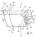
- the circuit breaker housing is composed of the housing shell acting as the housing base 49 and a further housing shell acting as the housing cover 148.
- the housing base 49 and the housing cover 148 are firmly connected to a fastening plate 149 parallel to the narrow sides.
- the fastening plate 149 projects beyond the narrow side of both housing shells in the transverse direction 50.
- the fastening plate 149 contains a fastening hole 150.
- the extent of the fastening plate 149 is limited in the transverse direction 50 by a fastening plate edge 151.
- the fastening plate edge 151 extends in the depth direction 44 arranged.
- the housing cover 148 contains a cover plate 152 arranged parallel to the plane spanned by the transverse direction 50 and the longitudinal direction 51. It has approximately a square outline shape. It can be removed from the housing cover 148 by fastening means, not shown here. These fastening means engage in four plate bores 153 arranged on the cover plate 152.
- the cover plate 152 covers the control electronics 2 fastened in the circuit breaker 1.
- the control electronics 2 are connected to the connection block 21 by connecting lines 16 (FIG. 15).
- the connection block 21 is arranged on the narrow side of the housing cover 148 facing away from the fastening plate 149. In the longitudinal direction 51, the connection block 21 protrudes from the housing cover 148.
- connection block 21 has a rectangular outline shape and contains ten connection sockets 20 on its surface.
- the two connection sockets 20 arranged next to one another in the depth direction 44 are each electrically connected in parallel. Measuring or display devices are connected to the connecting sockets 20, for example.
- Several circuit breakers 1 can also be connected in parallel.
- connection block 21 is inserted in a recess in the housing cover 148.
- the cover plate 152 is extended in the region of the connection block 21 in the longitudinal direction 51 in order to completely cover the recess.
- the viewing window 119 is arranged on the narrow side of the housing cover 148 carrying the connection block 21. In the rectangular viewing window 119, it is visually indicated whether the circuit is closed or open. A cutout on the narrow side of the housing cover 148 in the region of the viewing window 119 is also covered by an extension of the cover plate 152 in the longitudinal direction 51.
- the cylindrical connecting bolts 70, 70 ' which extend in the longitudinal direction 51, pass through the circuit breaker housing in the region of its fastening plate 149 opposite narrow side.
- Both connecting bolts 70, 70 ' run approximately in the division plane between housing base 49 and housing cover 148.
- An electrical consumer is connected to the two connecting bolts 70, 70' via power lines.
- the connecting bolts 70, 70 ' are electrically shielded from one another by a partition 154 formed on the housing base 49.
- the partition 154 is T-shaped as seen in the longitudinal direction 51.
- the T-crosspiece is arranged in the transverse direction 50 and corresponds to the expansion of the housing base 49 in this direction.
- the T-crosspiece forms an extension of the housing base 49 in the longitudinal direction 51, the T-crosspiece being arranged offset in the depth direction 44 with respect to the housing base 49.
- the extension of the circuit breaker housing in the transverse direction 50 is divided into two halves by the vertical T-leg which projects vertically from the T-crosspiece.
- the vertical leg forms a plane arranged vertically on the circuit breaker housing. Its extent in the depth direction 44 is somewhat larger than the corresponding extent of the housing base 49.
- the single-pole circuit breaker 1 can be seen in FIG. 15, but with the cover plate 152 removed.
- a circuit board 155 is fitted in the inner region which can be closed by the cover plate 152. It is arranged parallel to the plane spanned by the transverse direction 50 and the longitudinal direction 51.
- the entire control electronics 2 are located on the circuit board 155.
- a part of the control electronics 2 is a hybrid circuit 156.
- the connections for the additional switch 7 and the auxiliary switch 6 are also located on the circuit board.
- Five connecting lines 16 connect the control electronics 2 to the connection sockets 20 of the Terminal block 21. In each case two connecting sockets 20 arranged side by side in the depth direction 44 are connected in parallel. This allows an electrical coupling of several circuit breakers 1.
- a plurality of circuit breakers 1 can also be coupled by direct connections of the circuit boards 155.
- the housing base 49 and housing cover 148 are provided with openings, not shown, so that the conductor tracks relating to the same electrical signal on the circuit boards 155 of a plurality of circuit breakers 1 can be electrically connected in parallel via connecting wires. Except for a single connection block 21 for the connection, for example, of the external remote switch 8, the remaining connection blocks 21 are unnecessary in this case.
- housing cover 148 In the housing cover 148, four housing cover bores 157 are provided, which correspond to the plate bores 153 of the cover plate 152.
- a groove-like adjustment opening 158 is formed in the area of the electromagnetic switching drive 3 on the end face of the housing base 49 facing the housing cover 148. Through the adjustment opening 158, for example, a screwdriver can engage in the adjustment slot 34 of the shift rod 25 in order to adjust the drive lever 11 and the armature 23.
- FIG. 16 shows the construction of a three-pole circuit breaker. It is composed of three single-pole circuit breakers 1. All single-pole circuit breakers 1 are identical. The single-pole circuit breakers 1 are electrically or mechanically coupled to one another. The cams 122 of the drive levers 11 can be penetrated by a common coupling rod. In this case, the electromagnetic switching drives 17 of the two outer circuit breakers 1 can be omitted if the drive lever 11 has a sufficient power transmission. The coupling rod passing through the cams 122 of the drive levers 11 establishes a mechanical coupling of all the circuit breakers 1. Tripping a circuit breaker 1 causes the other circuit breakers 1 to trip at the same time. The inputs and outputs of several single-pole circuit breakers 1 can be connected in parallel via the connection blocks 21. With this electrical coupling, the triggering of a single-pole circuit breaker 1 by the control electronics 2 also triggers all other single-pole circuit breakers 1.
- FIG. 17 schematically shows the electrical coupling of three single-pole circuit breakers 1 to a three-pole or three-phase circuit breaker.
- the connections labeled "A1" and “A2” correspond to the connection bolts 70, 70 '.
- the mains cable or the electrical consumer are connected to the connecting bolts 70, 70 '.
- a parallel input 159 labeled “1a” is electrically connected to the input 15 of the two other circuit breakers 1. From Fig. 3 it can be seen that input 15 and parallel input 159 are connected in parallel.
- An output 160 labeled “2” is also connected in parallel to a parallel output 161 labeled "2a” (FIG. 3).
- the output 160 is connected to a connecting line 16 (FIG. 15).
Landscapes
- Physics & Mathematics (AREA)
- Electromagnetism (AREA)
- Breakers (AREA)
- Selective Calling Equipment (AREA)
Priority Applications (1)
| Application Number | Priority Date | Filing Date | Title |
|---|---|---|---|
| DE9321529U DE9321529U1 (de) | 1992-03-31 | 1993-03-24 | Fernsteuerbarer Schutzschalter |
Applications Claiming Priority (4)
| Application Number | Priority Date | Filing Date | Title |
|---|---|---|---|
| DE9204342U | 1992-03-31 | ||
| DE9204342 | 1992-03-31 | ||
| DE9208010U DE9208010U1 (de) | 1992-06-15 | 1992-06-15 | Fernsteuerbarer Schutzschalter |
| DE9208010U | 1992-06-15 |
Publications (3)
| Publication Number | Publication Date |
|---|---|
| EP0563774A2 true EP0563774A2 (fr) | 1993-10-06 |
| EP0563774A3 EP0563774A3 (en) | 1994-11-23 |
| EP0563774B1 EP0563774B1 (fr) | 1999-05-19 |
Family
ID=25959330
Family Applications (1)
| Application Number | Title | Priority Date | Filing Date |
|---|---|---|---|
| EP93104852A Expired - Lifetime EP0563774B1 (fr) | 1992-03-31 | 1993-03-24 | Disjoncteur de protection avec commande à distance |
Country Status (4)
| Country | Link |
|---|---|
| US (1) | US5381121A (fr) |
| EP (1) | EP0563774B1 (fr) |
| DE (1) | DE59309583D1 (fr) |
| ES (1) | ES2133339T3 (fr) |
Cited By (4)
| Publication number | Priority date | Publication date | Assignee | Title |
|---|---|---|---|---|
| WO2008119786A1 (fr) * | 2007-03-30 | 2008-10-09 | Abb Research Ltd | Actionneur magnétique bistable pour coupe-circuits avec circuit d'entraînement électronique et procédé de mise en œuvre dudit actionneur |
| WO2010102899A1 (fr) * | 2009-03-11 | 2010-09-16 | Siemens Aktiengesellschaft | Système de distribution d'énergie |
| US8289112B1 (en) | 2006-07-19 | 2012-10-16 | Euchner Gmbh & Co. Kg | Apparatus for monitoring the state of a protective device of a machine |
| EP2479774A3 (fr) * | 2011-01-19 | 2014-06-25 | Abb Ag | Appareil d'installation |
Families Citing this family (25)
| Publication number | Priority date | Publication date | Assignee | Title |
|---|---|---|---|---|
| DE19882165T1 (de) * | 1997-03-08 | 2000-03-30 | Blp Components Ltd | Zweipoliges Schütz |
| US6441708B1 (en) * | 1999-11-05 | 2002-08-27 | Siemens Energy & Automation, Inc. | Shunt trip device for a molded case circuit breaker |
| DE19960755A1 (de) * | 1999-12-16 | 2001-07-05 | Ellenberger & Poensgen | Simulationsschalter |
| FR2806524B1 (fr) * | 2000-03-17 | 2002-06-14 | Ge Power Controls France | Commande motorisee pour disjoncteur |
| FR2817078B1 (fr) * | 2000-11-21 | 2003-02-14 | Hager Electro | Dispositif de commande a distance pour appareillage modulaire de protection |
| US7324876B2 (en) * | 2001-07-10 | 2008-01-29 | Yingco Electronic Inc. | System for remotely controlling energy distribution at local sites |
| US7265652B2 (en) * | 2001-07-10 | 2007-09-04 | Yingco Electronic Inc. | Controllable electronic switch |
| US6636141B2 (en) | 2001-07-10 | 2003-10-21 | Yingco Electronic Inc. | Controllable electronic switch |
| US6545234B1 (en) | 2001-12-18 | 2003-04-08 | Abb Technology | Circuit breaker with mechanical interlock |
| DE10211534A1 (de) * | 2002-03-15 | 2003-10-16 | Siemens Ag | Auslösevorrichtung für ein Schaltgerät |
| US6768402B2 (en) | 2002-04-15 | 2004-07-27 | Eaton Corporation | Externally controllable circuit breaker |
| AU2002950581A0 (en) | 2002-08-02 | 2002-09-12 | Wayne Callen | Electrical safety circuit |
| DE102004019177A1 (de) * | 2004-04-16 | 2005-11-03 | Abb Patent Gmbh | Thermische Auslöseeinrichtung |
| US7692112B2 (en) * | 2006-01-10 | 2010-04-06 | Siemens Industry, Inc. | Control module |
| US7319373B2 (en) * | 2006-01-23 | 2008-01-15 | Eaton Corporation | Electrical switching apparatus and terminal housing therefor |
| US7570140B2 (en) * | 2006-03-02 | 2009-08-04 | Eaton Corporation | Magnetic trip mechanism including a plunger member engaging a support structure, and circuit breaker including the same |
| US7812695B2 (en) * | 2006-11-09 | 2010-10-12 | Siemens Industry, Inc. | Tie bar for three pole switching device |
| EP2254140B1 (fr) * | 2009-05-19 | 2013-11-27 | Abb Ag | Déclencheur de surintensité indépendant thermiquement |
| US8088633B2 (en) | 2009-12-02 | 2012-01-03 | Ultratech, Inc. | Optical alignment methods for forming LEDs having a rough surface |
| PL2431991T3 (pl) * | 2010-09-20 | 2013-08-30 | Secheron Sa | Mechanizm wyzwalający dla urządzenia przerywającego obwód |
| US8803640B2 (en) * | 2012-08-29 | 2014-08-12 | Carling Technologies, Inc. | Remote operated circuit breaker |
| US8872606B1 (en) * | 2013-04-23 | 2014-10-28 | Eaton Corporation | Bimetal and magnetic armature providing an arc splatter resistant offset therebetween, and circuit breaker including the same |
| US9911562B2 (en) * | 2014-05-14 | 2018-03-06 | Abb Schweiz Ag | Thomson coil based actuator |
| CN106463283B (zh) * | 2014-05-19 | 2018-12-21 | Abb瑞士股份有限公司 | 高速限制电气开关设备 |
| US10153119B2 (en) | 2015-09-28 | 2018-12-11 | Eaton Intelligent Power Limited | Articulated clinch joint for molded case circuit breaker |
Citations (8)
| Publication number | Priority date | Publication date | Assignee | Title |
|---|---|---|---|---|
| DE302042C (fr) * | ||||
| DE643205C (de) * | 1937-03-31 | Aeg | Mehrpoliger UEberstromkniehebelschalter | |
| US3211955A (en) * | 1960-03-29 | 1965-10-12 | Westinghouse Electric Corp | Circuit interrupting device |
| US3601562A (en) * | 1969-09-02 | 1971-08-24 | Ite Imperial Corp | Defeater lock for electrically operated circuit breaker |
| US3706100A (en) * | 1972-01-19 | 1972-12-12 | Cutler Hammer Inc | Remote control circuit breaker system |
| US3863186A (en) * | 1973-10-26 | 1975-01-28 | Cutler Hammer Inc | Three phase remote control circuit breaker |
| EP0099233A2 (fr) * | 1982-07-06 | 1984-01-25 | Texas Instruments Incorporated | Dispositif de commande d'un circuit |
| USRE32882E (en) * | 1982-01-01 | 1989-03-07 | Matsushita Electric Works, Ltd. | Remote control system circuit breaker |
Family Cites Families (12)
| Publication number | Priority date | Publication date | Assignee | Title |
|---|---|---|---|---|
| FR657824A (fr) * | 1927-07-20 | 1929-05-28 | Schiele & Bruchsaler Ind | Dispositif de déclenchement pour disjoncteurs électriques |
| DE518833C (de) * | 1929-12-25 | 1931-02-20 | Ernst Curt Loesche | Vorrichtung zum Abscheiden von Eisen und anderen Fremdstoffen fuer Zerkleinerungsvorrichtungen |
| BE402791A (fr) * | 1933-04-25 | |||
| CH245200A (de) * | 1945-07-27 | 1946-10-31 | Bbc Brown Boveri & Cie | Kombinierter thermischer und dynamischer Auslöser. |
| US3521127A (en) * | 1967-10-13 | 1970-07-21 | Airpax Electronics | Remotely operated circuit breaker |
| US3651436A (en) * | 1970-01-02 | 1972-03-21 | Texas Instruments Inc | Circuit breaker |
| US3594668A (en) * | 1970-01-02 | 1971-07-20 | Texas Instruments Inc | Remote control circuit breaker |
| US3706916A (en) * | 1972-01-19 | 1972-12-19 | Cutler Hammer Inc | Remote control circuit breaker system |
| US4317094A (en) * | 1980-05-21 | 1982-02-23 | Texas Instruments Incorporated | Remotely controlled circuit breaker system |
| US4502033A (en) * | 1982-07-06 | 1985-02-26 | Texas Instruments Incorporated | Circuit control device |
| US4475094A (en) * | 1982-07-06 | 1984-10-02 | Texas Instruments Incorporated | Circuit control device |
| DE8904063U1 (de) * | 1989-04-03 | 1989-06-22 | Ellenberger & Poensgen Gmbh, 8503 Altdorf | Druckknopfbetätigter Überstromschutzschalter |
-
1993
- 1993-03-24 EP EP93104852A patent/EP0563774B1/fr not_active Expired - Lifetime
- 1993-03-24 DE DE59309583T patent/DE59309583D1/de not_active Expired - Lifetime
- 1993-03-24 ES ES93104852T patent/ES2133339T3/es not_active Expired - Lifetime
- 1993-03-31 US US08/041,216 patent/US5381121A/en not_active Expired - Lifetime
Patent Citations (8)
| Publication number | Priority date | Publication date | Assignee | Title |
|---|---|---|---|---|
| DE302042C (fr) * | ||||
| DE643205C (de) * | 1937-03-31 | Aeg | Mehrpoliger UEberstromkniehebelschalter | |
| US3211955A (en) * | 1960-03-29 | 1965-10-12 | Westinghouse Electric Corp | Circuit interrupting device |
| US3601562A (en) * | 1969-09-02 | 1971-08-24 | Ite Imperial Corp | Defeater lock for electrically operated circuit breaker |
| US3706100A (en) * | 1972-01-19 | 1972-12-12 | Cutler Hammer Inc | Remote control circuit breaker system |
| US3863186A (en) * | 1973-10-26 | 1975-01-28 | Cutler Hammer Inc | Three phase remote control circuit breaker |
| USRE32882E (en) * | 1982-01-01 | 1989-03-07 | Matsushita Electric Works, Ltd. | Remote control system circuit breaker |
| EP0099233A2 (fr) * | 1982-07-06 | 1984-01-25 | Texas Instruments Incorporated | Dispositif de commande d'un circuit |
Cited By (6)
| Publication number | Priority date | Publication date | Assignee | Title |
|---|---|---|---|---|
| US8289112B1 (en) | 2006-07-19 | 2012-10-16 | Euchner Gmbh & Co. Kg | Apparatus for monitoring the state of a protective device of a machine |
| EP2041762B1 (fr) * | 2006-07-19 | 2014-07-16 | EUCHNER GmbH + Co. KG | Dispositif de surveillance de l'etat d'un dispositif de protection d'une machine |
| WO2008119786A1 (fr) * | 2007-03-30 | 2008-10-09 | Abb Research Ltd | Actionneur magnétique bistable pour coupe-circuits avec circuit d'entraînement électronique et procédé de mise en œuvre dudit actionneur |
| WO2008119785A1 (fr) * | 2007-03-30 | 2008-10-09 | Abb Research Ltd | Actionneur magnétique bistable pour coupe-circuits avec circuit d'entraînement électronique et procédé de mise en œuvre dudit actionneur |
| WO2010102899A1 (fr) * | 2009-03-11 | 2010-09-16 | Siemens Aktiengesellschaft | Système de distribution d'énergie |
| EP2479774A3 (fr) * | 2011-01-19 | 2014-06-25 | Abb Ag | Appareil d'installation |
Also Published As
| Publication number | Publication date |
|---|---|
| EP0563774B1 (fr) | 1999-05-19 |
| US5381121A (en) | 1995-01-10 |
| EP0563774A3 (en) | 1994-11-23 |
| ES2133339T3 (es) | 1999-09-16 |
| DE59309583D1 (de) | 1999-06-24 |
Similar Documents
| Publication | Publication Date | Title |
|---|---|---|
| EP0563774B1 (fr) | Disjoncteur de protection avec commande à distance | |
| DE60201210T2 (de) | Schutzschalter mit bewegbarer und beleuchtbarer Lichtbogenfehleranzeige | |
| WO2008128672A2 (fr) | Dispositif de verrouillage pour un appareil de coupure d'installation | |
| DE3713537C2 (de) | Umkehr-Schaltvorrichtung mit Überstromschutz | |
| EP1848020A2 (fr) | Coupe-circuit actionné manuellement | |
| WO1998032144A1 (fr) | Sectionneur de coupure en charge, en particulier pour circuit de charge d'une batterie d'un vehicule a moteur | |
| EP0303965B1 (fr) | Appareil de commutation électrique | |
| WO2013026518A1 (fr) | Dispositif d'entraînement pour un interrupteur à plusieurs positions | |
| EP1906426B1 (fr) | Appareil de commutation avec mécanisme de commande | |
| DE4406670C2 (de) | Leitungsschutzschalter | |
| DE1538529A1 (de) | Mehrpoliger UEberstromschalter | |
| DE19631533A1 (de) | Lastschaltanlagen zur hochspannungsseitigen Abschaltung von Verteiltransformatoren | |
| EP1884976B1 (fr) | Dispositif de commutation doté d'un élément d'actionnement | |
| DE4233918B4 (de) | Elektrischer Schalter mit Stromüberwachung | |
| DE2616554C2 (de) | Elektrischer Installationsschalter, insbesondere Leitungsschutzschalter mit Fehlerstromschutzeinrichtung | |
| EP3761335A1 (fr) | Appareil de commutation électronique | |
| EP0884747A2 (fr) | Appareil de commutation pour une installation électrique | |
| EP1671342B1 (fr) | Disjoncteur | |
| EP0802552A2 (fr) | Interrupteur électrique à déclenchement par manque de tension | |
| DE9321529U1 (de) | Fernsteuerbarer Schutzschalter | |
| DE19946735C1 (de) | Lasttrennschalter, vorzugsweise zum Einsatz in Kraftfahrzeugen | |
| DE102006036194B4 (de) | Schaltvorrichtung mit Schaltstellenpaar | |
| DE102011008829A1 (de) | Installationsschaltgerät | |
| WO2004047137A1 (fr) | Declencheur de secours pour disjoncteur de protection de moteur | |
| EP0310943B1 (fr) | Appareil de commutation électrique |
Legal Events
| Date | Code | Title | Description |
|---|---|---|---|
| PUAI | Public reference made under article 153(3) epc to a published international application that has entered the european phase |
Free format text: ORIGINAL CODE: 0009012 |
|
| AK | Designated contracting states |
Kind code of ref document: A2 Designated state(s): BE DE DK ES FR GB GR IE IT LU NL PT |
|
| GBC | Gb: translation of claims filed (gb section 78(7)/1977) | ||
| EL | Fr: translation of claims filed | ||
| ITCL | It: translation for ep claims filed |
Representative=s name: RICCARDI SERGIO & CO. |
|
| PUAL | Search report despatched |
Free format text: ORIGINAL CODE: 0009013 |
|
| AK | Designated contracting states |
Kind code of ref document: A3 Designated state(s): BE DE DK ES FR GB GR IE IT LU NL PT |
|
| 17P | Request for examination filed |
Effective date: 19941109 |
|
| 17Q | First examination report despatched |
Effective date: 19960423 |
|
| GRAG | Despatch of communication of intention to grant |
Free format text: ORIGINAL CODE: EPIDOS AGRA |
|
| GRAG | Despatch of communication of intention to grant |
Free format text: ORIGINAL CODE: EPIDOS AGRA |
|
| GRAG | Despatch of communication of intention to grant |
Free format text: ORIGINAL CODE: EPIDOS AGRA |
|
| GRAH | Despatch of communication of intention to grant a patent |
Free format text: ORIGINAL CODE: EPIDOS IGRA |
|
| GRAH | Despatch of communication of intention to grant a patent |
Free format text: ORIGINAL CODE: EPIDOS IGRA |
|
| GRAG | Despatch of communication of intention to grant |
Free format text: ORIGINAL CODE: EPIDOS AGRA |
|
| GRAG | Despatch of communication of intention to grant |
Free format text: ORIGINAL CODE: EPIDOS AGRA |
|
| GRAH | Despatch of communication of intention to grant a patent |
Free format text: ORIGINAL CODE: EPIDOS IGRA |
|
| GRAH | Despatch of communication of intention to grant a patent |
Free format text: ORIGINAL CODE: EPIDOS IGRA |
|
| GRAA | (expected) grant |
Free format text: ORIGINAL CODE: 0009210 |
|
| AK | Designated contracting states |
Kind code of ref document: B1 Designated state(s): BE DE DK ES FR GB GR IE IT LU NL PT |
|
| PG25 | Lapsed in a contracting state [announced via postgrant information from national office to epo] |
Ref country code: NL Free format text: LAPSE BECAUSE OF FAILURE TO SUBMIT A TRANSLATION OF THE DESCRIPTION OR TO PAY THE FEE WITHIN THE PRESCRIBED TIME-LIMIT Effective date: 19990519 Ref country code: GR Free format text: LAPSE BECAUSE OF NON-PAYMENT OF DUE FEES Effective date: 19990519 |
|
| REG | Reference to a national code |
Ref country code: IE Ref legal event code: FG4D Free format text: GERMAN |
|
| REF | Corresponds to: |
Ref document number: 59309583 Country of ref document: DE Date of ref document: 19990624 |
|
| ITF | It: translation for a ep patent filed | ||
| PG25 | Lapsed in a contracting state [announced via postgrant information from national office to epo] |
Ref country code: PT Free format text: LAPSE BECAUSE OF FAILURE TO SUBMIT A TRANSLATION OF THE DESCRIPTION OR TO PAY THE FEE WITHIN THE PRESCRIBED TIME-LIMIT Effective date: 19990819 Ref country code: DK Free format text: LAPSE BECAUSE OF FAILURE TO SUBMIT A TRANSLATION OF THE DESCRIPTION OR TO PAY THE FEE WITHIN THE PRESCRIBED TIME-LIMIT Effective date: 19990819 |
|
| ET | Fr: translation filed | ||
| REG | Reference to a national code |
Ref country code: ES Ref legal event code: FG2A Ref document number: 2133339 Country of ref document: ES Kind code of ref document: T3 |
|
| GBT | Gb: translation of ep patent filed (gb section 77(6)(a)/1977) |
Effective date: 19990929 |
|
| PG25 | Lapsed in a contracting state [announced via postgrant information from national office to epo] |
Ref country code: LU Free format text: LAPSE BECAUSE OF NON-PAYMENT OF DUE FEES Effective date: 20000324 |
|
| PLBE | No opposition filed within time limit |
Free format text: ORIGINAL CODE: 0009261 |
|
| STAA | Information on the status of an ep patent application or granted ep patent |
Free format text: STATUS: NO OPPOSITION FILED WITHIN TIME LIMIT |
|
| K2C3 | Correction of patent specification (complete document) published |
Effective date: 19990519 |
|
| PG25 | Lapsed in a contracting state [announced via postgrant information from national office to epo] |
Ref country code: BE Free format text: LAPSE BECAUSE OF NON-PAYMENT OF DUE FEES Effective date: 20000331 |
|
| 26N | No opposition filed | ||
| BERE | Be: lapsed |
Owner name: ELLENBERGER & POENSGEN G.M.B.H. Effective date: 20000331 |
|
| ET1 | Fr: translation filed ** revision of the translation of the patent or the claims | ||
| REG | Reference to a national code |
Ref country code: IE Ref legal event code: FD4D |
|
| REG | Reference to a national code |
Ref country code: GB Ref legal event code: IF02 |
|
| PGFP | Annual fee paid to national office [announced via postgrant information from national office to epo] |
Ref country code: ES Payment date: 20030325 Year of fee payment: 11 |
|
| PG25 | Lapsed in a contracting state [announced via postgrant information from national office to epo] |
Ref country code: ES Free format text: LAPSE BECAUSE OF NON-PAYMENT OF DUE FEES Effective date: 20040325 |
|
| PG25 | Lapsed in a contracting state [announced via postgrant information from national office to epo] |
Ref country code: IT Free format text: LAPSE BECAUSE OF NON-PAYMENT OF DUE FEES;WARNING: LAPSES OF ITALIAN PATENTS WITH EFFECTIVE DATE BEFORE 2007 MAY HAVE OCCURRED AT ANY TIME BEFORE 2007. THE CORRECT EFFECTIVE DATE MAY BE DIFFERENT FROM THE ONE RECORDED. Effective date: 20050324 |
|
| REG | Reference to a national code |
Ref country code: ES Ref legal event code: FD2A Effective date: 20040325 |
|
| PGFP | Annual fee paid to national office [announced via postgrant information from national office to epo] |
Ref country code: FR Payment date: 20110401 Year of fee payment: 19 |
|
| PGFP | Annual fee paid to national office [announced via postgrant information from national office to epo] |
Ref country code: GB Payment date: 20110324 Year of fee payment: 19 Ref country code: DE Payment date: 20110323 Year of fee payment: 19 |
|
| GBPC | Gb: european patent ceased through non-payment of renewal fee |
Effective date: 20120324 |
|
| REG | Reference to a national code |
Ref country code: FR Ref legal event code: ST Effective date: 20121130 |
|
| PG25 | Lapsed in a contracting state [announced via postgrant information from national office to epo] |
Ref country code: GB Free format text: LAPSE BECAUSE OF NON-PAYMENT OF DUE FEES Effective date: 20120324 Ref country code: FR Free format text: LAPSE BECAUSE OF NON-PAYMENT OF DUE FEES Effective date: 20120402 |
|
| REG | Reference to a national code |
Ref country code: DE Ref legal event code: R119 Ref document number: 59309583 Country of ref document: DE Effective date: 20121002 |
|
| PG25 | Lapsed in a contracting state [announced via postgrant information from national office to epo] |
Ref country code: DE Free format text: LAPSE BECAUSE OF NON-PAYMENT OF DUE FEES Effective date: 20121002 |