EP1906426B1 - Appareil de commutation avec mécanisme de commande - Google Patents
Appareil de commutation avec mécanisme de commande Download PDFInfo
- Publication number
- EP1906426B1 EP1906426B1 EP06020611A EP06020611A EP1906426B1 EP 1906426 B1 EP1906426 B1 EP 1906426B1 EP 06020611 A EP06020611 A EP 06020611A EP 06020611 A EP06020611 A EP 06020611A EP 1906426 B1 EP1906426 B1 EP 1906426B1
- Authority
- EP
- European Patent Office
- Prior art keywords
- handle
- switching device
- switched
- tripper
- switch
- Prior art date
- Legal status (The legal status is an assumption and is not a legal conclusion. Google has not performed a legal analysis and makes no representation as to the accuracy of the status listed.)
- Not-in-force
Links
Images


Classifications
-
- H—ELECTRICITY
- H01—ELECTRIC ELEMENTS
- H01H—ELECTRIC SWITCHES; RELAYS; SELECTORS; EMERGENCY PROTECTIVE DEVICES
- H01H71/00—Details of the protective switches or relays covered by groups H01H73/00 - H01H83/00
- H01H71/04—Means for indicating condition of the switching device
-
- H—ELECTRICITY
- H01—ELECTRIC ELEMENTS
- H01H—ELECTRIC SWITCHES; RELAYS; SELECTORS; EMERGENCY PROTECTIVE DEVICES
- H01H71/00—Details of the protective switches or relays covered by groups H01H73/00 - H01H83/00
- H01H71/04—Means for indicating condition of the switching device
- H01H2071/042—Means for indicating condition of the switching device with different indications for different conditions, e.g. contact position, overload, short circuit or earth leakage
-
- H—ELECTRICITY
- H01—ELECTRIC ELEMENTS
- H01H—ELECTRIC SWITCHES; RELAYS; SELECTORS; EMERGENCY PROTECTIVE DEVICES
- H01H71/00—Details of the protective switches or relays covered by groups H01H73/00 - H01H83/00
- H01H71/04—Means for indicating condition of the switching device
- H01H2071/046—Means for indicating condition of the switching device exclusively by position of operating part, e.g. with additional labels or marks but no other movable indicators
-
- H—ELECTRICITY
- H01—ELECTRIC ELEMENTS
- H01H—ELECTRIC SWITCHES; RELAYS; SELECTORS; EMERGENCY PROTECTIVE DEVICES
- H01H71/00—Details of the protective switches or relays covered by groups H01H73/00 - H01H83/00
- H01H71/10—Operating or release mechanisms
- H01H71/50—Manual reset mechanisms which may be also used for manual release
- H01H71/56—Manual reset mechanisms which may be also used for manual release actuated by rotatable knob or wheel
Definitions
- the invention relates to a switching device with a switch lock for mechanical actuation of the switching device, with a first trigger to protect against overload, with a second trigger for protection against short circuit and with a handle for actuating the switching mechanism or a method for indicating the cause of shutdown such switching device.
- a circuit breaker For the protection of electrical consumers, e.g. Motors, a circuit breaker is usually used, wherein it has a time-delayed trigger for protection against overload and a temporally instantaneous trigger for protection against short circuit.
- the switching mechanism of the circuit breaker is mechanically coupled to the triggers, the shutter can break the circuit by automatically opening switch contacts and cause the shutdown of the electrical load.
- the switch contacts can also be opened or closed manually by means of a handle of the circuit breaker, wherein the handle is mechanically coupled to the switch lock or integrated in the switch lock.
- the ON state (switched-on breaker) and the OFF state (switched-off breaker) can be seen by the position of the handle.
- a circuit breaker has a handle which is arranged outside of the switch housing.
- the handle is brought into an intermediate position, also known as a tripped position, between off and adjustment, when the circuit breaker is switched off by a shutter to protect against overload or short circuit. Only the shutdown of the circuit breaker is indicated by the position of the handle, but it can not be distinguished between overload and short circuit.
- some devices use a lamp a visible add-on module or visibly indicated by an integrated additional display which caused the trigger to trip.
- the use of a mountable add-on module or an integrated additional display is on the one hand in the manufacturing cost of circuit breakers unfavorable and on the other hand, the simplification of the structure or the miniaturization of the size of circuit breakers is difficult.
- US 2004/008098 A1 discloses a switching device according to the preamble of claim 1, and a method according to the preamble of claim 8.
- the invention has for its object to visually distinguish the Abschaltursachen a switching device.
- the invention has for its object to indicate in a switching device by the position of the handle the triggering reason. If a switching device which has a switching mechanism for mechanical operation of the switching device, a first trigger for protection against overload, a second trigger for protection against short circuit and a handle for actuating the switching mechanism to indicate the shutdown cause of the switching device, then the switching device is so formed to move the handle to a first position when the first trigger is triggered due to an overload, and the handle is moved to a second position when the second trigger is triggered because of a short circuit, wherein the first and the second position different are.
- the cause of the trip can also be identified in a simple manner without additional indication. There is also no need for additional space on the small viewing surface on the switch housing for other display elements.
- the handle for manual operation of the switching device is provided.
- the handle for actuating the switch lock is designed such that the switching device is turned on when the handle is moved to a third position, and that the switching device is turned off when the handle is moved to a fourth position. All four positions differ from each other.
- the switching device is designed such that the handle is passed into the four positions by a rotational movement.
- Each of the four positions can be represented by a symbol or a character and arranged in a rotatable handle, for example. In a circle. Rotary motion allows the handle to reach any position and indicate the status and shutdown causes of the switchgear.
- the switching device has a switching gear, which is formed, generates the rotational movement of the handle.
- the switching gear By the switching gear, the rotational movement of the handle can be transferred to the switch lock, or vice versa.
- the switching mechanism is designed such that upon release of the first trigger, the handle is moved to the first position and locked in the first position, and that upon release of the second trigger, the handle moves to the second position and locked there.
- the handle can also be moved to the third or fourth position and locked there when the switching device is switched on or off.
- the handle has at least one toothed segment, which is formed with the switching gear to lock the handle in one of the four positions.
- such a switching device is used as a circuit breaker or as a device having a circuit breaker, to protect the current paths between an electrical supply and consumers.
- the switching device can be manually switched off or on by rotation of the handle 4.
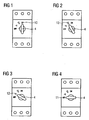
- the handle 4 receives a total of four positions 10, 11, 12 and 13 are provided. The four positions 10, 11, 12 and 13 represent the on state, the off state, the shutdown due to overload and the shutdown due to short circuit for the switching device, respectively.
- the first 12 and the second position 13 of the handle 4 are located between the third 10 and fourth position 11, wherein the angle of rotation of the handle 4 between the third position 10, in which the handle indicates the ON position of the device, and the fourth position 11, in which the handle 4 indicates the OFF position, is 90 °.
- Each position 10, 11, 12 and 13 is represented differently by an icon (or label) for easier recognition.
- the switching device When you turn the handle 4 to the ON position 10 ( FIG. 1 ), the switching device is switched on. If the handle 4, however, turned to the OFF position 11 ( FIG. 4 ), the switching device is switched off. In addition, the handle 4 can move automatically in position 12 or 13 and locked or locked there ( 3 and 2 ), if the switching device shuts off automatically due to overload or short circuit.
- the switching device When the switching device is switched off, for example due to overload, the handle 4 moves from the ON position 10 via the position 13, which indicates the triggering due to short circuit, in the position 12 and is locked in this position 12, to further rotation after to prevent the OFF position 11. This makes it possible, by the handle 4 in addition to the on and off state to be able to display the reasons for switching off the switching device recognizable without an additional component must be used.
- FIG. 5 shows the schematic structure of a switched-off switching device above.
- the switching device has a first trigger 2 for protection against overload and a second trigger 3 for protection against short circuit.
- the first trigger 2 is preferably a time-delayed thermo-bimetallic release
- the second trigger 3 is preferably an instantaneous electromagnetic release, which further comprises a coil 17 with an armature 16.
- the handle 4 has a toothed segment 6, and the switching mechanism 1 summarizes a mounted on a stationary axis switching gear 5 and at least one connecting lever 7 to.
- the handle 4 is mechanically coupled to the switching mechanism 1.
- the switching mechanism 1 is mechanically coupled to the triggers 2 and 3 respectively.
- a spring 15 is provided for exerting a force on the lever 9, so that the switching mechanism 1 can actuate the triggers 2 and 3 or the handle 4 by its mechanical movement, conversely the same applies.
- the handle 4 When the handle 4 is rotated to the position 11, the handle 4 engages by means of the toothed segment 6 in the shift gear 5 and rotates the shift gear 5. By the rotation of the shift gear 5, the switching mechanism 1, the switch contacts 14 open. As a result, the switching device is turned off, and at the same time, the handle 4 indicates the off state of the switching device in the OFF position 11.
- FIG. 6 A switched on same switching device is in FIG. 6 shown schematically.
- the handle 4 When the handle 4 is turned to the ON position 10, the handle 4 operates in the same manner the switch lock 1.
- the switch contacts 14 are closed to turn on the switching device again, while the handle 4 shows the on state of the switching device in the ON position 10 on.
- FIG. 7 the switching device has been switched off due to a short circuit.
- the lever 9 In normal operation, the lever 9 is mounted on the spring 15 and presses the spring 15 together. When short circuit, the armature 16 dips into the coil 17 of the trigger 3 and the lever 9 is thereby released. The lever 9 is pressed by the relaxed spring force against the handle 4 and locks the handle 4 in the position 13. At the same time the switch contacts 1, the switching contacts 14 open. Thus, the switching device is switched off and at the same time the handle 4 indicates the Abschaltground as a short circuit in the position 13.
- FIG. 8 the switching device has been switched off due to an overload.
- the bimetal of the trigger 2 heats up.
- the switching mechanism 1 is actuated via the lever 8.
- the coupled with him handle 4 is moved to position 12 and locked there.
- the switch contacts 14 are then opened.
- the switching device is switched off and indicates the handle 4 the Abschaltground as overload in the 12 position.
Landscapes
- Breakers (AREA)
- Driving Mechanisms And Operating Circuits Of Arc-Extinguishing High-Tension Switches (AREA)
- Emergency Protection Circuit Devices (AREA)
- Lock And Its Accessories (AREA)
Claims (13)
- Appareil de commutation comportant un mécanisme de commande (1) pour l'actionnement mécanique de l'appareil de commutation, un premier déclencheur (2) pour la protection contre la surcharge, un deuxième déclencheur (3) pour la protection contre les courts-circuits, et une manette (4) pour actionner le mécanisme de commande (1), caractérisé en ce que l'appareil de commutation est réalisé pour faire passer la manette (4) dans une première position lorsque le déclenchement du premier déclencheur (2) se produit et pour faire passer la manette (4) dans une deuxième position (13) lorsque le déclenchement du deuxième déclencheur (3) se produit, la première position (12) et la deuxième position (13) étant différentes.
- Appareil de commutation selon la revendication 1, caractérisé en ce que la manette (4) pour l'actionnement du mécanisme de commande (1) est réalisée de façon que l'appareil de commutation est enclenché lorsque la manette (4) se trouve dans une troisième position (10) et en ce que l'appareil de commutation est coupé lorsque la manette (4) se trouve dans une quatrième position (11), les quatre positions (10, 11, 12 et 13) étant différentes les unes des autres.
- Appareil de commutation selon la revendication 1 ou 2, caractérisé en ce que l'appareil de commutation est réalisé pour faire passer la manette (4) dans les quatre positions (10, 11, 12 et 13) par un mouvement de rotation.
- Appareil de commutation selon la revendication 3, caractérisé en ce que l'appareil de commutation comporte un engrenage de commutation (5) qui est réalisé pour générer le mouvement de rotation de la manette (4).
- Appareil de commutation selon l'une des revendications précédentes, caractérisé en ce que le mécanisme de commande (1) est réalisé pour, au déclenchement du premier déclencheur (2), faire passer la manette (4) dans la première position (12) et la bloquer dans la première position (12), pour, au déclenchement du deuxième déclencheur (3), faire passer la manette (4) dans la deuxième position (13) et la bloquer dans la deuxième position (13), pour bloquer la manette (4) dans la troisième position (10) à l'enclenchement de l'appareil de commutation et pour bloquer la manette (4) dans la quatrième position (11) à la coupure de l'appareil de commutation.
- Appareil de commutation selon l'une des revendications précédentes, caractérisé en ce que la manette (4) comporte au moins un segment denté (6) qui est réalisé, conjointement avec l'engrenage de commutation (5), pour bloquer la manette (4) dans l'une des quatre positions (10, 11, 12 et 13).
- Appareil de commutation selon l'une des revendications 1 à 6, l'appareil de commutation étant un commutateur de puissance ou un appareil qui comporte un commutateur de puissance.
- Procédé pour afficher la cause de la coupure d'un appareil de commutation, l'appareil de commutation comportant un premier déclencheur (2) pour la protection contre la surcharge, un deuxième déclencheur (3) pour la protection contre les courts-circuits, un mécanisme de commande (1) pour l'actionnement mécanique de l'appareil de commutation et une manette (4) pour actionner le mécanisme de commande (1), caractérisé en ce que la manette (4) subit un déplacement vers une première position (12) lorsque le déclenchement du premier déclencheur (2) se produit et la manette (4) subit un déplacement vers une deuxième position (13) lorsque le déclenchement du deuxième déclencheur (3) se produit, et la première position (12) et la deuxième position (13) étant différentes.
- Procédé selon la revendication 8, caractérisé en ce que l'appareil de commutation s'enclenche lorsque la manette (4) subit un déplacement vers une troisième position (10) et l'appareil de commutation se coupe lorsque la manette (4) subit un déplacement vers une quatrième position (11), les quatre positions (10, 11, 12, 13) étant différentes les unes des autres.
- Procédé selon la revendication 8 ou 9, caractérisé en ce que la manette (4) passe dans les quatre positions (10, 11, 12 et 13) du fait d'un mouvement de rotation.
- Procédé selon la revendication 10, caractérisé en ce que le mouvement de rotation de la manette (4) est généré par un engrenage de commutation (5).
- Procédé selon l'une des revendications 8 à 11, caractérisé en ce que la manette (4), au déclenchement du premier déclencheur (2), subit un déplacement vers la première position et est bloquée dans la première position, la manette (4), au déclenchement du deuxième déclencheur (3), subit un déplacement vers la deuxième position et est bloquée dans la deuxième position, la manette (4) est bloquée dans la troisième position (10) à l'enclenchement de l'appareil de commutation et la manette (4) est bloquée dans la quatrième position (11) à la coupure de l'appareil de commutation.
- Procédé selon la revendication 12, caractérisé en ce que la manette (4) est bloquée par le fait que la manette (4) comporte au moins un segment denté (6).
Priority Applications (6)
| Application Number | Priority Date | Filing Date | Title |
|---|---|---|---|
| AT06020611T ATE430985T1 (de) | 2006-09-29 | 2006-09-29 | Schaltgerät mit schaltschloss |
| EP06020611A EP1906426B1 (fr) | 2006-09-29 | 2006-09-29 | Appareil de commutation avec mécanisme de commande |
| DE502006003677T DE502006003677D1 (de) | 2006-09-29 | 2006-09-29 | Schaltgerät mit Schaltschloss |
| CN2007101366693A CN101154538B (zh) | 2006-09-29 | 2007-07-18 | 具有开关锁扣的开关装置 |
| US11/900,340 US7583170B2 (en) | 2006-09-29 | 2007-09-11 | Switching device with switch latch |
| JP2007246526A JP4624390B2 (ja) | 2006-09-29 | 2007-09-25 | 開閉装置および開閉装置における遮断原因の表示方法 |
Applications Claiming Priority (1)
| Application Number | Priority Date | Filing Date | Title |
|---|---|---|---|
| EP06020611A EP1906426B1 (fr) | 2006-09-29 | 2006-09-29 | Appareil de commutation avec mécanisme de commande |
Publications (2)
| Publication Number | Publication Date |
|---|---|
| EP1906426A1 EP1906426A1 (fr) | 2008-04-02 |
| EP1906426B1 true EP1906426B1 (fr) | 2009-05-06 |
Family
ID=37808306
Family Applications (1)
| Application Number | Title | Priority Date | Filing Date |
|---|---|---|---|
| EP06020611A Not-in-force EP1906426B1 (fr) | 2006-09-29 | 2006-09-29 | Appareil de commutation avec mécanisme de commande |
Country Status (6)
| Country | Link |
|---|---|
| US (1) | US7583170B2 (fr) |
| EP (1) | EP1906426B1 (fr) |
| JP (1) | JP4624390B2 (fr) |
| CN (1) | CN101154538B (fr) |
| AT (1) | ATE430985T1 (fr) |
| DE (1) | DE502006003677D1 (fr) |
Families Citing this family (7)
| Publication number | Priority date | Publication date | Assignee | Title |
|---|---|---|---|---|
| DE102012008129A1 (de) * | 2011-07-25 | 2013-01-31 | Abb Technology Ag | Verriegelungsvorrichtung für eine Antriebseinheit zur Betätigung eines Schaltgerätes einer Schaltanlage |
| FR3023969B1 (fr) * | 2014-07-17 | 2017-12-22 | Schneider Electric Ind Sas | Dispositif de signalisation d'un defaut electrique dans un appareil de protection electrique, et appareil comportant un tel dispositif |
| CN104752111A (zh) * | 2015-03-04 | 2015-07-01 | 浙江天正电气股份有限公司 | 一种塑壳断路器 |
| KR200481214Y1 (ko) | 2015-06-24 | 2016-08-30 | 엘에스산전 주식회사 | 가스절연개폐장치의 조작기구 잠금장치 |
| CN106328402B (zh) * | 2015-06-30 | 2018-07-03 | 上海电科电器科技有限公司 | 电器开关的指示装置 |
| CN105225865B (zh) * | 2015-09-02 | 2017-12-15 | 福建逢兴机电设备有限公司 | 一种高压柜安全装置 |
| FR3051593B1 (fr) * | 2016-05-23 | 2019-10-04 | Schneider Electric Industries Sas | Dispositif de signalisation d'un defaut electrique dans un appareil de protection electrique, et appareil de protection electrique comportant un tel dispositif. |
Family Cites Families (9)
| Publication number | Priority date | Publication date | Assignee | Title |
|---|---|---|---|---|
| JPS631403Y2 (fr) * | 1980-02-15 | 1988-01-14 | ||
| FR2538160B1 (fr) * | 1982-12-20 | 1985-12-13 | Telemecanique Electrique | Appareil contacteur a actionnement electromagnetique controle et a ouverture automatique lors de l'apparition de surcharges |
| US4598183A (en) * | 1984-07-27 | 1986-07-01 | Square D Company | Trip indicating circuit breaker operating handle |
| GB2246909B (en) * | 1990-07-16 | 1995-02-22 | Terasaki Denki Sangyo Kk | Circuit breaker including forced contact parting mechanism capable of self-retaining under short circuit condition |
| JP2517495B2 (ja) * | 1991-06-12 | 1996-07-24 | 寺崎電気産業株式会社 | 回路遮断器 |
| FR2799573B1 (fr) * | 1999-10-11 | 2001-12-14 | Schneider Electric Ind Sa | Mecanisme de commande de disjoncteur |
| JP3966058B2 (ja) * | 2002-04-19 | 2007-08-29 | 富士電機機器制御株式会社 | 回路しゃ断器 |
| CN1320579C (zh) * | 2005-07-06 | 2007-06-06 | 浙江中凯电器有限公司 | 一种控制与保护开关电器的操作机构 |
| CN1741224A (zh) * | 2005-07-27 | 2006-03-01 | 上海电器科学研究所(集团)有限公司 | 双推杆控制单一常开触头的故障区分操作机构 |
-
2006
- 2006-09-29 AT AT06020611T patent/ATE430985T1/de not_active IP Right Cessation
- 2006-09-29 EP EP06020611A patent/EP1906426B1/fr not_active Not-in-force
- 2006-09-29 DE DE502006003677T patent/DE502006003677D1/de active Active
-
2007
- 2007-07-18 CN CN2007101366693A patent/CN101154538B/zh not_active Expired - Fee Related
- 2007-09-11 US US11/900,340 patent/US7583170B2/en not_active Expired - Fee Related
- 2007-09-25 JP JP2007246526A patent/JP4624390B2/ja not_active Expired - Fee Related
Also Published As
| Publication number | Publication date |
|---|---|
| ATE430985T1 (de) | 2009-05-15 |
| CN101154538A (zh) | 2008-04-02 |
| US7583170B2 (en) | 2009-09-01 |
| CN101154538B (zh) | 2010-06-23 |
| EP1906426A1 (fr) | 2008-04-02 |
| DE502006003677D1 (de) | 2009-06-18 |
| JP4624390B2 (ja) | 2011-02-02 |
| JP2008091333A (ja) | 2008-04-17 |
| US20080079518A1 (en) | 2008-04-03 |
Similar Documents
| Publication | Publication Date | Title |
|---|---|---|
| EP1906426B1 (fr) | Appareil de commutation avec mécanisme de commande | |
| EP0563774B1 (fr) | Disjoncteur de protection avec commande à distance | |
| EP3131106B1 (fr) | Dispositif de verrouillage d'une installation de commutation a haute tension | |
| EP2137746B1 (fr) | Dispositif de verrouillage pour un appareil de coupure d'installation | |
| DE102009023347A1 (de) | Handbetätigter Schutzschalter mit austauschbarem Auslösemodul | |
| EP2436021B1 (fr) | Unité de commutation pour un disjoncteur doté d'un culbuteur | |
| DE102008011522B4 (de) | Einschubschaltgerät zum Einschieben in eine Einschubkassette eines Schaltschranks und zur Verwendung bei einer Niederspannung oder Mittelspannung | |
| DE202006015517U1 (de) | Mechanische Sicherheitsvorrichtung für Schaltgeräte | |
| EP1671342B1 (fr) | Disjoncteur | |
| DE102010019741B4 (de) | Schaltmechanik für einen Fehlerstromschutzschalter sowie Fehlerstromschutzschalter | |
| DE102008016575B4 (de) | Voll-Schutzschalter und motorsteuerbarer Vollschutzschalter | |
| EP2059941B1 (fr) | Bloc de contacts auxiliaires pour l'extension d'un contacteur | |
| WO2007124775A1 (fr) | Commutateur de sécurité électrique | |
| EP0310943B1 (fr) | Appareil de commutation électrique | |
| DE102011018498A1 (de) | Elektrisches Installationsgerät und System umfassend ein Installationsschaltgerät und einen Hilfsschalter | |
| DE102012203042B4 (de) | Schaltvorrichtung und Elektrisches Schaltgerät | |
| EP0820084B1 (fr) | Dispositif de commande pour disjoncteurs | |
| DE3412325C2 (fr) | ||
| DE102009020396B4 (de) | Fehlerstromschutzschalter | |
| EP2637270B1 (fr) | Cadre amovible pour un appareil de commutation électrique enfichable, notamment un disjoncteur enfichable | |
| EP2533264B1 (fr) | Commutateur auxiliaire pour un commutateur électrique | |
| EP3210228A1 (fr) | Actionneur rotatif | |
| DE102012215482B3 (de) | Vorrichtung zum Betätigen eines elektrischen Schalters | |
| EP1912230A2 (fr) | Disjoncteur sectionneur avec entraînement à ressort | |
| DE102007005674B3 (de) | Elektromechanisches Schaltgerät und Vorrichtung mit einem elektromechnanischen Schaltgerät |
Legal Events
| Date | Code | Title | Description |
|---|---|---|---|
| PUAI | Public reference made under article 153(3) epc to a published international application that has entered the european phase |
Free format text: ORIGINAL CODE: 0009012 |
|
| AK | Designated contracting states |
Kind code of ref document: A1 Designated state(s): AT BE BG CH CY CZ DE DK EE ES FI FR GB GR HU IE IS IT LI LT LU LV MC NL PL PT RO SE SI SK TR |
|
| AX | Request for extension of the european patent |
Extension state: AL BA HR MK YU |
|
| 17P | Request for examination filed |
Effective date: 20080424 |
|
| GRAP | Despatch of communication of intention to grant a patent |
Free format text: ORIGINAL CODE: EPIDOSNIGR1 |
|
| AKX | Designation fees paid |
Designated state(s): AT BE BG CH CY CZ DE DK EE ES FI FR GB GR HU IE IS IT LI LT LU LV MC NL PL PT RO SE SI SK TR |
|
| GRAS | Grant fee paid |
Free format text: ORIGINAL CODE: EPIDOSNIGR3 |
|
| GRAA | (expected) grant |
Free format text: ORIGINAL CODE: 0009210 |
|
| AK | Designated contracting states |
Kind code of ref document: B1 Designated state(s): AT BE BG CH CY CZ DE DK EE ES FI FR GB GR HU IE IS IT LI LT LU LV MC NL PL PT RO SE SI SK TR |
|
| REG | Reference to a national code |
Ref country code: GB Ref legal event code: FG4D Free format text: NOT ENGLISH |
|
| REG | Reference to a national code |
Ref country code: CH Ref legal event code: EP |
|
| REG | Reference to a national code |
Ref country code: IE Ref legal event code: FG4D |
|
| REF | Corresponds to: |
Ref document number: 502006003677 Country of ref document: DE Date of ref document: 20090618 Kind code of ref document: P |
|
| PG25 | Lapsed in a contracting state [announced via postgrant information from national office to epo] |
Ref country code: ES Free format text: LAPSE BECAUSE OF FAILURE TO SUBMIT A TRANSLATION OF THE DESCRIPTION OR TO PAY THE FEE WITHIN THE PRESCRIBED TIME-LIMIT Effective date: 20090817 Ref country code: PT Free format text: LAPSE BECAUSE OF FAILURE TO SUBMIT A TRANSLATION OF THE DESCRIPTION OR TO PAY THE FEE WITHIN THE PRESCRIBED TIME-LIMIT Effective date: 20090906 Ref country code: LT Free format text: LAPSE BECAUSE OF FAILURE TO SUBMIT A TRANSLATION OF THE DESCRIPTION OR TO PAY THE FEE WITHIN THE PRESCRIBED TIME-LIMIT Effective date: 20090506 Ref country code: FI Free format text: LAPSE BECAUSE OF FAILURE TO SUBMIT A TRANSLATION OF THE DESCRIPTION OR TO PAY THE FEE WITHIN THE PRESCRIBED TIME-LIMIT Effective date: 20090506 |
|
| NLV1 | Nl: lapsed or annulled due to failure to fulfill the requirements of art. 29p and 29m of the patents act | ||
| PG25 | Lapsed in a contracting state [announced via postgrant information from national office to epo] |
Ref country code: IS Free format text: LAPSE BECAUSE OF FAILURE TO SUBMIT A TRANSLATION OF THE DESCRIPTION OR TO PAY THE FEE WITHIN THE PRESCRIBED TIME-LIMIT Effective date: 20090906 Ref country code: SE Free format text: LAPSE BECAUSE OF FAILURE TO SUBMIT A TRANSLATION OF THE DESCRIPTION OR TO PAY THE FEE WITHIN THE PRESCRIBED TIME-LIMIT Effective date: 20090806 Ref country code: PL Free format text: LAPSE BECAUSE OF FAILURE TO SUBMIT A TRANSLATION OF THE DESCRIPTION OR TO PAY THE FEE WITHIN THE PRESCRIBED TIME-LIMIT Effective date: 20090506 Ref country code: SI Free format text: LAPSE BECAUSE OF FAILURE TO SUBMIT A TRANSLATION OF THE DESCRIPTION OR TO PAY THE FEE WITHIN THE PRESCRIBED TIME-LIMIT Effective date: 20090506 Ref country code: LV Free format text: LAPSE BECAUSE OF FAILURE TO SUBMIT A TRANSLATION OF THE DESCRIPTION OR TO PAY THE FEE WITHIN THE PRESCRIBED TIME-LIMIT Effective date: 20090506 Ref country code: NL Free format text: LAPSE BECAUSE OF FAILURE TO SUBMIT A TRANSLATION OF THE DESCRIPTION OR TO PAY THE FEE WITHIN THE PRESCRIBED TIME-LIMIT Effective date: 20090506 |
|
| REG | Reference to a national code |
Ref country code: IE Ref legal event code: FD4D |
|
| PG25 | Lapsed in a contracting state [announced via postgrant information from national office to epo] |
Ref country code: CZ Free format text: LAPSE BECAUSE OF FAILURE TO SUBMIT A TRANSLATION OF THE DESCRIPTION OR TO PAY THE FEE WITHIN THE PRESCRIBED TIME-LIMIT Effective date: 20090506 Ref country code: RO Free format text: LAPSE BECAUSE OF FAILURE TO SUBMIT A TRANSLATION OF THE DESCRIPTION OR TO PAY THE FEE WITHIN THE PRESCRIBED TIME-LIMIT Effective date: 20090506 Ref country code: EE Free format text: LAPSE BECAUSE OF FAILURE TO SUBMIT A TRANSLATION OF THE DESCRIPTION OR TO PAY THE FEE WITHIN THE PRESCRIBED TIME-LIMIT Effective date: 20090506 Ref country code: IE Free format text: LAPSE BECAUSE OF FAILURE TO SUBMIT A TRANSLATION OF THE DESCRIPTION OR TO PAY THE FEE WITHIN THE PRESCRIBED TIME-LIMIT Effective date: 20090506 Ref country code: DK Free format text: LAPSE BECAUSE OF FAILURE TO SUBMIT A TRANSLATION OF THE DESCRIPTION OR TO PAY THE FEE WITHIN THE PRESCRIBED TIME-LIMIT Effective date: 20090506 |
|
| PG25 | Lapsed in a contracting state [announced via postgrant information from national office to epo] |
Ref country code: SK Free format text: LAPSE BECAUSE OF FAILURE TO SUBMIT A TRANSLATION OF THE DESCRIPTION OR TO PAY THE FEE WITHIN THE PRESCRIBED TIME-LIMIT Effective date: 20090506 |
|
| PLBE | No opposition filed within time limit |
Free format text: ORIGINAL CODE: 0009261 |
|
| STAA | Information on the status of an ep patent application or granted ep patent |
Free format text: STATUS: NO OPPOSITION FILED WITHIN TIME LIMIT |
|
| BERE | Be: lapsed |
Owner name: SIEMENS A.G. Effective date: 20090930 |
|
| PG25 | Lapsed in a contracting state [announced via postgrant information from national office to epo] |
Ref country code: BG Free format text: LAPSE BECAUSE OF FAILURE TO SUBMIT A TRANSLATION OF THE DESCRIPTION OR TO PAY THE FEE WITHIN THE PRESCRIBED TIME-LIMIT Effective date: 20090806 |
|
| 26N | No opposition filed |
Effective date: 20100209 |
|
| PG25 | Lapsed in a contracting state [announced via postgrant information from national office to epo] |
Ref country code: MC Free format text: LAPSE BECAUSE OF NON-PAYMENT OF DUE FEES Effective date: 20090930 |
|
| PG25 | Lapsed in a contracting state [announced via postgrant information from national office to epo] |
Ref country code: BE Free format text: LAPSE BECAUSE OF NON-PAYMENT OF DUE FEES Effective date: 20090930 |
|
| PG25 | Lapsed in a contracting state [announced via postgrant information from national office to epo] |
Ref country code: GR Free format text: LAPSE BECAUSE OF FAILURE TO SUBMIT A TRANSLATION OF THE DESCRIPTION OR TO PAY THE FEE WITHIN THE PRESCRIBED TIME-LIMIT Effective date: 20090807 |
|
| PG25 | Lapsed in a contracting state [announced via postgrant information from national office to epo] |
Ref country code: AT Free format text: LAPSE BECAUSE OF NON-PAYMENT OF DUE FEES Effective date: 20090929 |
|
| PG25 | Lapsed in a contracting state [announced via postgrant information from national office to epo] |
Ref country code: LU Free format text: LAPSE BECAUSE OF NON-PAYMENT OF DUE FEES Effective date: 20090929 |
|
| REG | Reference to a national code |
Ref country code: CH Ref legal event code: PL |
|
| GBPC | Gb: european patent ceased through non-payment of renewal fee |
Effective date: 20100929 |
|
| PG25 | Lapsed in a contracting state [announced via postgrant information from national office to epo] |
Ref country code: HU Free format text: LAPSE BECAUSE OF FAILURE TO SUBMIT A TRANSLATION OF THE DESCRIPTION OR TO PAY THE FEE WITHIN THE PRESCRIBED TIME-LIMIT Effective date: 20091107 |
|
| PG25 | Lapsed in a contracting state [announced via postgrant information from national office to epo] |
Ref country code: CH Free format text: LAPSE BECAUSE OF NON-PAYMENT OF DUE FEES Effective date: 20100930 Ref country code: LI Free format text: LAPSE BECAUSE OF NON-PAYMENT OF DUE FEES Effective date: 20100930 |
|
| PG25 | Lapsed in a contracting state [announced via postgrant information from national office to epo] |
Ref country code: TR Free format text: LAPSE BECAUSE OF FAILURE TO SUBMIT A TRANSLATION OF THE DESCRIPTION OR TO PAY THE FEE WITHIN THE PRESCRIBED TIME-LIMIT Effective date: 20090506 Ref country code: GB Free format text: LAPSE BECAUSE OF NON-PAYMENT OF DUE FEES Effective date: 20100929 |
|
| PG25 | Lapsed in a contracting state [announced via postgrant information from national office to epo] |
Ref country code: CY Free format text: LAPSE BECAUSE OF FAILURE TO SUBMIT A TRANSLATION OF THE DESCRIPTION OR TO PAY THE FEE WITHIN THE PRESCRIBED TIME-LIMIT Effective date: 20090506 |
|
| PGFP | Annual fee paid to national office [announced via postgrant information from national office to epo] |
Ref country code: DE Payment date: 20151120 Year of fee payment: 10 |
|
| REG | Reference to a national code |
Ref country code: FR Ref legal event code: PLFP Year of fee payment: 11 |
|
| PGFP | Annual fee paid to national office [announced via postgrant information from national office to epo] |
Ref country code: FR Payment date: 20160914 Year of fee payment: 11 |
|
| PGFP | Annual fee paid to national office [announced via postgrant information from national office to epo] |
Ref country code: IT Payment date: 20160928 Year of fee payment: 11 |
|
| REG | Reference to a national code |
Ref country code: DE Ref legal event code: R119 Ref document number: 502006003677 Country of ref document: DE |
|
| PG25 | Lapsed in a contracting state [announced via postgrant information from national office to epo] |
Ref country code: DE Free format text: LAPSE BECAUSE OF NON-PAYMENT OF DUE FEES Effective date: 20170401 |
|
| REG | Reference to a national code |
Ref country code: FR Ref legal event code: ST Effective date: 20180531 |
|
| PG25 | Lapsed in a contracting state [announced via postgrant information from national office to epo] |
Ref country code: FR Free format text: LAPSE BECAUSE OF NON-PAYMENT OF DUE FEES Effective date: 20171002 Ref country code: IT Free format text: LAPSE BECAUSE OF NON-PAYMENT OF DUE FEES Effective date: 20170929 |