EP0802369B1 - Lampenabdeckung für eine Aussenleuchte, insbesondere Mast-Aufsetzleuchte - Google Patents
Lampenabdeckung für eine Aussenleuchte, insbesondere Mast-Aufsetzleuchte Download PDFInfo
- Publication number
- EP0802369B1 EP0802369B1 EP97102269A EP97102269A EP0802369B1 EP 0802369 B1 EP0802369 B1 EP 0802369B1 EP 97102269 A EP97102269 A EP 97102269A EP 97102269 A EP97102269 A EP 97102269A EP 0802369 B1 EP0802369 B1 EP 0802369B1
- Authority
- EP
- European Patent Office
- Prior art keywords
- luminaire
- lamp
- lamp cover
- case
- cover according
- Prior art date
- Legal status (The legal status is an assumption and is not a legal conclusion. Google has not performed a legal analysis and makes no representation as to the accuracy of the status listed.)
- Expired - Lifetime
Links
Images

Classifications
-
- F—MECHANICAL ENGINEERING; LIGHTING; HEATING; WEAPONS; BLASTING
- F21—LIGHTING
- F21S—NON-PORTABLE LIGHTING DEVICES; SYSTEMS THEREOF; VEHICLE LIGHTING DEVICES SPECIALLY ADAPTED FOR VEHICLE EXTERIORS
- F21S8/00—Lighting devices intended for fixed installation
- F21S8/08—Lighting devices intended for fixed installation with a standard
- F21S8/085—Lighting devices intended for fixed installation with a standard of high-built type, e.g. street light
- F21S8/088—Lighting devices intended for fixed installation with a standard of high-built type, e.g. street light with lighting device mounted on top of the standard, e.g. for pedestrian zones
-
- F—MECHANICAL ENGINEERING; LIGHTING; HEATING; WEAPONS; BLASTING
- F21—LIGHTING
- F21V—FUNCTIONAL FEATURES OR DETAILS OF LIGHTING DEVICES OR SYSTEMS THEREOF; STRUCTURAL COMBINATIONS OF LIGHTING DEVICES WITH OTHER ARTICLES, NOT OTHERWISE PROVIDED FOR
- F21V11/00—Screens not covered by groups F21V1/00, F21V3/00, F21V7/00 or F21V9/00
-
- F—MECHANICAL ENGINEERING; LIGHTING; HEATING; WEAPONS; BLASTING
- F21—LIGHTING
- F21V—FUNCTIONAL FEATURES OR DETAILS OF LIGHTING DEVICES OR SYSTEMS THEREOF; STRUCTURAL COMBINATIONS OF LIGHTING DEVICES WITH OTHER ARTICLES, NOT OTHERWISE PROVIDED FOR
- F21V17/00—Fastening of component parts of lighting devices, e.g. shades, globes, refractors, reflectors, filters, screens, grids or protective cages
- F21V17/10—Fastening of component parts of lighting devices, e.g. shades, globes, refractors, reflectors, filters, screens, grids or protective cages characterised by specific fastening means or way of fastening
- F21V17/14—Bayonet-type fastening
-
- F—MECHANICAL ENGINEERING; LIGHTING; HEATING; WEAPONS; BLASTING
- F21—LIGHTING
- F21V—FUNCTIONAL FEATURES OR DETAILS OF LIGHTING DEVICES OR SYSTEMS THEREOF; STRUCTURAL COMBINATIONS OF LIGHTING DEVICES WITH OTHER ARTICLES, NOT OTHERWISE PROVIDED FOR
- F21V21/00—Supporting, suspending, or attaching arrangements for lighting devices; Hand grips
- F21V21/10—Pendants, arms, or standards; Fixing lighting devices to pendants, arms, or standards
- F21V21/116—Fixing lighting devices to arms or standards
-
- F—MECHANICAL ENGINEERING; LIGHTING; HEATING; WEAPONS; BLASTING
- F21—LIGHTING
- F21V—FUNCTIONAL FEATURES OR DETAILS OF LIGHTING DEVICES OR SYSTEMS THEREOF; STRUCTURAL COMBINATIONS OF LIGHTING DEVICES WITH OTHER ARTICLES, NOT OTHERWISE PROVIDED FOR
- F21V29/00—Protecting lighting devices from thermal damage; Cooling or heating arrangements specially adapted for lighting devices or systems
- F21V29/15—Thermal insulation
-
- F—MECHANICAL ENGINEERING; LIGHTING; HEATING; WEAPONS; BLASTING
- F21—LIGHTING
- F21V—FUNCTIONAL FEATURES OR DETAILS OF LIGHTING DEVICES OR SYSTEMS THEREOF; STRUCTURAL COMBINATIONS OF LIGHTING DEVICES WITH OTHER ARTICLES, NOT OTHERWISE PROVIDED FOR
- F21V3/00—Globes; Bowls; Cover glasses
- F21V3/02—Globes; Bowls; Cover glasses characterised by the shape
Definitions
- the invention relates to one with a pole or similar vertical support arranged lamp holder especially for road or the like Outdoor lights detachably connected lamp cover, consisting from a lamp glass surrounding the lamp Plastic, one inside it at the level of the lamp arranged blind ring made of metal, one above the Lamp arranged outside of the lamp glass and in its central area penetrated by the lamp glass and towered luminaire roof and one inside the luminaire glass in the part that dominates the luminaire roof arranged funnel-shaped heat protection body Metal.
- Lamp covers with these features are already in various embodiments in trade and therefore generally known.
- LABEL la SEYNE-SUR-MER, France, becomes an outdoor lamp offered for sale with such a lamp cover.
- Similar lights are also used by other companies, e.g. in an advertising brochure by HESS-FORM + LICHT in Villingen-Schwenningen, and in a company catalog Hellux-Leuchten GmbH in Laatzen.
- the glare ring arranged at the height of the lamp is intended for direct glare prevent.
- the blind rings are in different Designs translucent to some extent, e.g. in that it consists of conical washers downward outer edges are composed (HELLUX). So the lamp is only a short distance away from the location of the lamp with an upward view visible.
- the funnel-shaped heat protection body (NORAL) arranged above the lamp keeps the particularly upward heat emission of the lamp away from this area of the lamp cover.
- NORAL With the lamp from NORAL, the lamp cover can be removed, for example to replace the lamp, in such a way that it is connected to the lower part of the lamp so that it can be tilted to the side by means of a side hinge bracket.
- the known lights of this type are very expensive to construct. They consist of a large number of components. A whole series of operations are required for their manufacture and assembly. As a result, luminaires of this type are very expensive even by the lamp cover alone.
- the invention has for its object a lamp cover for an outdoor lamp, especially a pole-mounted lamp to create the easily and quickly solvable with the arranged on a pole or the like carrier Luminaire bracket is connected, which is structurally simpler is made up of fewer individual parts, in fewer Operations can be produced and assembled and the without disadvantages in terms of lighting effect and material Quality is cheaper than the known lamp covers with lights of this type.
- the lamp cover according to the invention essentially consists of a lamp glass 1 made of a thermoplastic plastic, which is designed as a one-piece hollow body closed at the top, a blind ring 3 arranged in the lamp glass 1 at the level of the lamp 2 , a heat protection body 4 arranged above the lamp 2 in the lamp glass 1 and a lamp roof 5 arranged on the lamp glass 1 in its upper region .
- the lamp glass 1 is an essentially cylindrical hollow body made of a polycarbonate. At the level of the lamp 2, it has an extension 6 of its cross section in the form of a wide annular groove. In it, the blind ring 3 is held against the inner wall of the lamp glass 1 .
- the blind ring 3 consists of a metal sheet. It has the shape of a simple smooth cylinder in this embodiment for simplicity of illustration. At least one of its edges can be angled outwards, so that the metal sheet heated by the lamp 2 does not touch the entire surface of the lamp surface, but only the narrow wall of the lamp glass.
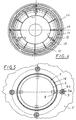
- the wall has a system of slots which are arranged in pairs offset from one another on ring lines, the wall surfaces located between two slots lying one above the other being inclined against the cylinder axis and thus each forming a circular sector of a conical jacket segment.
- the blind ring 3 can, for example, also be designed in the manner of a scraper with downward outward scraper edges.
- the two last-mentioned embodiments have the advantage that with the choice of the inclination of the wall sections of the blind ring 3 which is possible through the slot system, an optimum can be selected between the greatest possible floor lighting on the one hand and the dimming of horizontal light radiation on the other hand.
- the lamp glass 1 has a central dome-shaped elevation 7 at the top, which protrudes from a central opening in the lamp roof 5 .
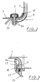
- the heat protection body 4 is arranged therein. This is formed as a funnel-like molding made of sheet metal and fastened with distance from the inner wall of the luminaire case 1 by means arranged on its upper edge, from there downward and with their ends radially angled webs 8 on the lamp glass.
- Screws 9 are provided as fastening means, which are inserted from the outside through the inner edge region of the lamp roof 5 , the shoulder region of the lamp glass 1 and bores in the ends of the webs 8 .
- a disk 9b made of heat-insulating material is placed on the screw 9 between the wall of the lamp glass 1 and the screw nut 9a holding the web.
- the lamp glass 1 is fastened to the lamp holder 10 by means of a bayonet connection.
- the lamp glass 1 reduced to a short edge section 11 with a smaller diameter, has circular sector-shaped flange sections 12 , the upper sides of which each form an inclined plane rising in the same direction, a gap 13 being provided between the two adjacent flange sections 12 .
- the lamp holder 10 is provided at the top with a cylindrical outer rim 14 on the inner side in the spacings of the gaps 13 between the flange portions 12 of the lamp glass 1 cams 15 are arranged.
- the invention is not limited to the embodiment described above and shown in the drawing and the alternative forms of the blind ring mentioned.
- the lamp glass 1 and the lamp roof 5 can also have other shapes in which the features according to claim 1 are included.
Landscapes
- Engineering & Computer Science (AREA)
- General Engineering & Computer Science (AREA)
- Non-Portable Lighting Devices Or Systems Thereof (AREA)
- Arrangement Of Elements, Cooling, Sealing, Or The Like Of Lighting Devices (AREA)
- Securing Globes, Refractors, Reflectors Or The Like (AREA)
Description
Bei der Leuchte von NORAL ist die Lampenabdeckung, z.B. zum Auswechseln der Lampe, in der Weise abnehmbar, daß sie durch eine seitliche Gelenkhalterung mit dem Leuchtenunterteil seitlich abkippbar verbunden ist.
Die bekannten Leuchten dieser Art sind konstruktiv sehr aufwendig. Sie bestehen aus einer Vielzahl von Bauteilen. Für ihre Herstellung und Montage wird eine ganze Reihe von Arbeitsgängen benötigt. Dadurch sind solche Leuchten schon durch die Lampenabdeckung allein sehr teuer.
- Fig. 1
- Ein axiales Schnittbild durch eine Mast-Aufsetzleuchte mit einer erfindungsgemäßen Lampenabdekkung,
- Fig. 2
- eine vergrößerte Darstellung des Ausschnittes A der Fig. 1,
- Fig. 3
- eine vergrößerte Darstellung des Ausschnittes B der Fig. 1,
- Fig. 4
- einen Querschnitt nach der Linie C - C in Fig. 1 in größerem Maßstab,
- Fig. 5
- eine Draufsicht auf den zentralen Bereich der Lampenabdeckung, ebenfalls in größerem Maßstab.
Der Blendring 3 besteht aus einem Metallblech. Er hat bei diesem Ausführungsbeispiel der einfacheren Darstellung wegen die Form eines einfachen glatten Zylinders. Wenigstens einer seiner Ränder kann nach außen gewinkelt sein, so daß das von der Lampe 2 erwärmte Blech nicht mit seiner ganzen Fläche, sondern nur mit schmalen Zonen die Innenwand des Leuchtenglases berührt. Er kann aber auch in der Weise weitergebildet sein, daß seine Wand ein System von auf Ringlinien jeweils paarweise versetzt zueinander angeordneten Schlitzen aufweist, wobei die jeweils zwischen zwei übereinanderliegenden Schlitzen befindlichen Wandflächen gegen die Zylinderachse geneigt sind und so jeweils einen Kreissektor eines Kegelmantelsegmentes bilden.
Der Blendring 3 kann beispielsweise auch raffelblechartig mit abwärts nach außen gerichteten Raffelrändern ausgebildet sein. Die beiden letztgenannten Ausführungsformen haben den Vorteil, daß mit der durch das Schlitzsystem möglichen Wahl der Neigung der Wandabschnitte des Blendringes 3 ein Optimum wählbar ist zwischen einer möglichst weiten Bodenbeleuchtung einerseits und der Abblendung waagerechter Lichtstrahlung andererseits.
Claims (11)
- Mit einer auf einem Rohrmast oder dergleichen senkrechten Träger angeordneten Leuchtenhalterung (10) für Straßen- oder dergleichen Außenleuchten lösbar verbundene Lampenabdeckung bestehend aus einem die Lampe (2) umgebenden Leuchtenglas (1) aus Kunststoff, einem innerhalb desselben in Höhe der Lampe (2) angeordneten Blendring (3) aus Metallblech, einem oberhalb der Lampe (2) außerhalb des Leuchtenglases (1) angeordneten und in seinem zentralen Bereich vom Leuchtenglas (1) durchdrungenen und überragten Leuchtendach (5) und einem innerhalb des Leuchtenglases (1) in dessen das Leuchtendach (5) überragenden Teil angeordneten trichterförmigen Wärmeschutzkörper 4 aus Metall,
dadurch gekennzeichnet, daßdas Leuchtenglas (1) in Höhe der Lampe (2) eine scharf abgesetzte Zone mit einer Erweiterung (6) seines Querschnittes aufweist, in welcher der Blendring (3) in axialer Richtung unverschiebbar fixiert ist,das obere Ende des Leuchtenglases (1) als domartige, durch eine zentrale Öffnung des Leuchtendaches (5) aus diesem heraustretende Erhöhung (7) ausgebildet ist, in welcher der Wärmeschutzkörper (4) mit Abstand vom Leuchtenglas (1) angeordnet ist undder untere Rand des Leuchtenglases (1) eine Komponente einer Bajonettverbindung mit der Leuchtenhalterung (10) aufweist. - Lampenabdeckung nach Anspruch 1,
dadurch gekennzeichnet, daß das Leuchtenglas (1) als zylindrischer Hohlkörper ausgebildet ist, wobei die in Höhe der Lampe (2) vorgesehene Erweiterung (6) seines Querschnittes als flache, der Höhe des Blendringes (3) entsprechende und diesen aufnehmende Ringnut ausgebildet ist. - Lampenabdeckung nach einem der Ansprüche 1 oder 2,
dadurch gekennzeichnet, daß der Blendring (3) als Rohrabschnitt ausgebildet ist. - Lampenabdeckung nach einem der Ansprüche 1 bis 3,
dadurch gekennzeichnet, daß die Wand des Blendringes (3) mit einem System von jeweils paarweise übereinander angeordneten Querschlitzen versehen ist, wobei die jeweils zwischen zwei übereinander verlaufenden Querschlitzen befindlichen Wandflächenabschnitte gegen die Rohrachse geneigt sind, derart, daß sie jeweils einen Sektor eines Kegelmantelsegmentes bilden. - Lampenabdeckung nach einem der Ansprüche 1 bis 3,
dadurch gekennzeichnet, daß die Wand des Blendringes (3) raffelblechartig mit abwärts nach außen gerichteten Raffelrändern ausgebildet ist. - Lampenabdeckung nach einem der Ansprüche 1 bis 5,
dadurch gekennzeichnet, daß der Wärmeschutzkörper (4) als trichterförmiges Formteil aus Metallblech ausgebildet und mittels an seinem oberen Rand angeordneter, von dort abwärts gerichteter und mit ihren Enden radial abgewinkelter Stege (8) in dem unterhalb der domartigen Erhöhung (7) gebildeten Schulterbereich des Leuchtenglases (1) befestigt ist. - Lampenabdeckung nach einem der Ansprüche 1 bis 6,
dadurch gekennzeichnet, daß als Befestigungsmittel für den Wärmeschutzkörper (4) von außen durch Bohrungen im Randbereich des Leuchtendaches (5), sowie im Schulterbereich des Leuchtenglases (1) und in den Enden der Stege (8) gesteckte Schrauben (9) mit Muttern (9a) vorgesehen sind, wobei zwischen den Stegen (8) und der Wand des Leuchtenglases (1) Scheiben (9b) aus wärmedämmendem Material eingelegt sind. - Lampenabdeckung nach einem der Ansprüche 1 bis 7,
dadurch gekennzeichnet, daß das Leuchtenglas (1) mittels einer an sich bekannten Bajonettverbindung auf der Leuchtenhalterung (10) lösbar befestigt ist, wobei die eine Komponente der Bajonettverbindung am unteren Rand des Leuchtenglases (1) und die andere Komponente am oberen Rand der Leuchtenhalterung (10) angeformt ist. - Lampenabdeckung nach Anspruch 8,
dadurch gekennzeichnet, daß das unten auf einem kurzen Randabschnitt (11) mit geringerem Durchmesser reduzierte Leuchtenglas (1) kreissektorförmige Flanschabschnitte (12) aufweist, deren Oberseiten jeweils eine in gleicher Richtung ansteigende schiefe Ebene bilden, wobei jeweils zwischen zwei benachbarten Flanschabschnitten (12) eine Lücke (13) vorgesehen ist und als Gegenkomponente der Bajonettverbindung die Leuchtenhalterung (10) oben mit einem zylindrischen Außenrand (14) versehen ist, an dessen Innenseite den Abständen der zwischen den Flanschabschnitten (12) des Leuchtenglases (1) vorhandene Lücken (13) die Flanschabschnitte (12) übergreifende Nocken (15) angeordnet sind. - Lampenabdeckung nach einem der Ansprüche 1 bis 9,
dadurch gekennzeichnet, daß der Blendring (3) aus mehreren Ringelementen zusammengesetzt ist. - Lampenabdeckung nach Anspruch 10,
dadurch gekennzeichnet, daß zwischen den Ringelementen Durchlässe vorgesehen sind.
Applications Claiming Priority (2)
| Application Number | Priority Date | Filing Date | Title |
|---|---|---|---|
| DE29606988U | 1996-04-19 | ||
| DE29606988U DE29606988U1 (de) | 1996-04-19 | 1996-04-19 | Lampenabdeckung für eine Außenleuchte, insbesondere Mast-Aufsetzleuchte |
Publications (3)
| Publication Number | Publication Date |
|---|---|
| EP0802369A2 EP0802369A2 (de) | 1997-10-22 |
| EP0802369A3 EP0802369A3 (de) | 1998-09-02 |
| EP0802369B1 true EP0802369B1 (de) | 2001-11-07 |
Family
ID=8022719
Family Applications (1)
| Application Number | Title | Priority Date | Filing Date |
|---|---|---|---|
| EP97102269A Expired - Lifetime EP0802369B1 (de) | 1996-04-19 | 1997-02-13 | Lampenabdeckung für eine Aussenleuchte, insbesondere Mast-Aufsetzleuchte |
Country Status (5)
| Country | Link |
|---|---|
| US (1) | US5921663A (de) |
| EP (1) | EP0802369B1 (de) |
| JP (1) | JPH09330607A (de) |
| AT (1) | ATE208479T1 (de) |
| DE (3) | DE29606988U1 (de) |
Families Citing this family (18)
| Publication number | Priority date | Publication date | Assignee | Title |
|---|---|---|---|---|
| DE29810886U1 (de) | 1998-06-18 | 1998-09-24 | Wila Leuchten Ag, Sevelen | Anordnung bestehend aus zumindest zwei miteinander verbundenen ringförmigen Körpern sowie Leuchte mit einer solchen Anordnung |
| US6511196B1 (en) * | 2000-11-20 | 2003-01-28 | Richard Dale Hoy | Container with illuminated interior visual display |
| DE60231484D1 (de) | 2001-04-09 | 2009-04-23 | Eveready Battery Inc | Verbesserte beleuchtungsvorrichtung |
| US6926490B2 (en) * | 2003-01-21 | 2005-08-09 | Hamilton Sundstrand | Self-actuated bearing cooling flow shut-off valve |
| DE602005016210D1 (de) * | 2004-10-04 | 2009-10-08 | Philips Intellectual Property | Lampensockel mit verbesserter wärmeleitung |
| US7387409B1 (en) * | 2006-03-01 | 2008-06-17 | Beadle Joshua Z | Pathway light fixture with interchangeable components |
| DE102006014003A1 (de) * | 2006-03-27 | 2007-10-04 | Berchtold Holding Gmbh | Medizinische Leuchte |
| US8770801B1 (en) | 2007-05-01 | 2014-07-08 | Musco Corporation | Apparatus and method for pathway or similar lighting |
| US8827512B1 (en) * | 2008-10-19 | 2014-09-09 | Hunter Industries Incorporated | Pathway light fixture with releasably sealed lamp enclosure |
| CA2764322C (en) * | 2009-06-11 | 2015-10-27 | Relume Technologies, Inc. | Solar shield for led light emitting assembly |
| DE102011052580A1 (de) * | 2011-08-11 | 2013-02-14 | Hella Kgaa Hueck & Co. | Außenleuchte mit Korrosionssicherung |
| US9091416B1 (en) | 2011-10-11 | 2015-07-28 | Deepsea Power & Light, Inc. | Pathway illumination devices, methods, and systems |
| US9863590B2 (en) | 2011-10-11 | 2018-01-09 | Deepsea Power & Light, Inc. | Pathway lights |
| US9052091B2 (en) * | 2012-03-27 | 2015-06-09 | Wahine Holdings, L.L.C. | Alignment base for elongated lighting fixture |
| DE202013105401U1 (de) * | 2013-11-27 | 2015-03-02 | Bhs-Pro Gmbh | Aufsatzleuchte |
| CN104613413A (zh) * | 2015-03-12 | 2015-05-13 | 苏州昆仑工业设计有限公司 | 一种组合板式吊灯 |
| US10356886B1 (en) | 2018-01-30 | 2019-07-16 | Musco Corporation | Apparatus, method, and system for theatrical lighting of poles or other structures from a mounted position on the pole or other structure |
| CN110345434A (zh) * | 2019-07-24 | 2019-10-18 | 应晓强 | Led景观灯 |
Family Cites Families (8)
| Publication number | Priority date | Publication date | Assignee | Title |
|---|---|---|---|---|
| US3679891A (en) * | 1970-01-20 | 1972-07-25 | Holophane Co Inc | Lighting fixture adapted to be mounted on a pole |
| US3806236A (en) * | 1972-02-28 | 1974-04-23 | Gen Electric | High intensity projection lamp assembly with heat shield |
| US4434455A (en) * | 1981-05-01 | 1984-02-28 | Merritt William H | Differential light emission translucent light bowl and cap |
| US4719548A (en) * | 1986-08-27 | 1988-01-12 | King Luminaire Co., Inc. | Prismatic globe for street luminaire |
| DE9015538U1 (de) * | 1990-11-09 | 1991-01-31 | Weller, Jürgen, 4150 Krefeld | Strassenleuchte |
| US5297013A (en) * | 1991-08-09 | 1994-03-22 | Brinkmann Corporation | Outdoor light fixture |
| US5331527A (en) * | 1992-12-11 | 1994-07-19 | Stokes Dana A | Decorative outdoor light |
| DE29516931U1 (de) * | 1995-10-26 | 1995-12-21 | Trilux-Lenze Gmbh + Co Kg, 59759 Arnsberg | Außenleuchte |
-
1996
- 1996-04-19 DE DE29606988U patent/DE29606988U1/de not_active Expired - Lifetime
- 1996-09-02 DE DE19635521A patent/DE19635521A1/de not_active Withdrawn
-
1997
- 1997-02-13 DE DE59705235T patent/DE59705235D1/de not_active Expired - Fee Related
- 1997-02-13 AT AT97102269T patent/ATE208479T1/de not_active IP Right Cessation
- 1997-02-13 EP EP97102269A patent/EP0802369B1/de not_active Expired - Lifetime
- 1997-03-13 JP JP9059569A patent/JPH09330607A/ja not_active Withdrawn
- 1997-04-21 US US08/843,803 patent/US5921663A/en not_active Expired - Fee Related
Also Published As
| Publication number | Publication date |
|---|---|
| EP0802369A3 (de) | 1998-09-02 |
| US5921663A (en) | 1999-07-13 |
| EP0802369A2 (de) | 1997-10-22 |
| DE19635521A1 (de) | 1997-10-23 |
| DE29606988U1 (de) | 1996-07-11 |
| DE59705235D1 (de) | 2001-12-13 |
| JPH09330607A (ja) | 1997-12-22 |
| ATE208479T1 (de) | 2001-11-15 |
Similar Documents
| Publication | Publication Date | Title |
|---|---|---|
| EP0802369B1 (de) | Lampenabdeckung für eine Aussenleuchte, insbesondere Mast-Aufsetzleuchte | |
| EP1848921B1 (de) | Leuchte mit länglicher lichtquelle und lichtbeeinflussungselement | |
| DE2210242A1 (de) | Beleuchtungskörper | |
| EP0716262B1 (de) | Leuchte für langgestreckte Leuchtmittel | |
| DE8709038U1 (de) | Leuchte mit asymmetrischem Lichtbündel | |
| EP0802368A2 (de) | Leuchte mit einer insbesonderen kleinvolumigen Lampe | |
| EP0396504A1 (de) | Leuchte | |
| EP0483626B1 (de) | Aussenleuchte | |
| DE10139002B4 (de) | Einbauleuchte | |
| DE202018000708U1 (de) | Pfettenprofil, Terrassenüberdachung | |
| DE1497316A1 (de) | Beleuchtungskoerper mit Rueckstrahlvorrichtung | |
| CH680684A5 (en) | Anti dazzle light fitting suitable for halogen bulbs | |
| WO1991007621A1 (de) | Leuchte | |
| DE102011101610B3 (de) | Leuchte | |
| DE4210439C2 (de) | Vorsatzsystem für eine Strahlerleuchte | |
| AT380117B (de) | Verkehrssignalampel | |
| EP0770819B1 (de) | Aussenleuchte | |
| DE2054470A1 (de) | Beleuchtungskonstruktion | |
| DE29906884U1 (de) | Beleuchtungseinrichtung mit einer Tragbasis | |
| DE202007013177U1 (de) | Leuchte | |
| DE4319638A1 (de) | Leuchte mit Ringblenden-Optik | |
| DE8706542U1 (de) | Deckeneinbauleuchte mit Energiesparlampe | |
| DE9308796U1 (de) | Leuchte mit Ringblenden-Optik | |
| DE9106904U1 (de) | Reflektorschirmleuchte | |
| DE202025104020U1 (de) | Außenleuchte |
Legal Events
| Date | Code | Title | Description |
|---|---|---|---|
| PUAI | Public reference made under article 153(3) epc to a published international application that has entered the european phase |
Free format text: ORIGINAL CODE: 0009012 |
|
| AK | Designated contracting states |
Kind code of ref document: A2 Designated state(s): AT BE CH DE ES FR GB IT LI |
|
| PUAL | Search report despatched |
Free format text: ORIGINAL CODE: 0009013 |
|
| AK | Designated contracting states |
Kind code of ref document: A3 Designated state(s): AT BE CH DE ES FR GB IT LI |
|
| RHK1 | Main classification (correction) |
Ipc: F21S 1/10 |
|
| 17P | Request for examination filed |
Effective date: 19981021 |
|
| GRAG | Despatch of communication of intention to grant |
Free format text: ORIGINAL CODE: EPIDOS AGRA |
|
| 17Q | First examination report despatched |
Effective date: 20010605 |
|
| GRAG | Despatch of communication of intention to grant |
Free format text: ORIGINAL CODE: EPIDOS AGRA |
|
| GRAH | Despatch of communication of intention to grant a patent |
Free format text: ORIGINAL CODE: EPIDOS IGRA |
|
| GRAH | Despatch of communication of intention to grant a patent |
Free format text: ORIGINAL CODE: EPIDOS IGRA |
|
| GRAA | (expected) grant |
Free format text: ORIGINAL CODE: 0009210 |
|
| AK | Designated contracting states |
Kind code of ref document: B1 Designated state(s): AT BE CH DE ES FR GB IT LI |
|
| REF | Corresponds to: |
Ref document number: 208479 Country of ref document: AT Date of ref document: 20011115 Kind code of ref document: T |
|
| RIC1 | Information provided on ipc code assigned before grant |
Free format text: 7F 21S 8/08 A, 7F 21V 29/00 B, 7F 21V 21/10 B, 7F 21V 11/16 B |
|
| REG | Reference to a national code |
Ref country code: CH Ref legal event code: EP |
|
| REF | Corresponds to: |
Ref document number: 59705235 Country of ref document: DE Date of ref document: 20011213 |
|
| REG | Reference to a national code |
Ref country code: GB Ref legal event code: IF02 |
|
| ET | Fr: translation filed | ||
| GBT | Gb: translation of ep patent filed (gb section 77(6)(a)/1977) |
Effective date: 20020110 |
|
| PG25 | Lapsed in a contracting state [announced via postgrant information from national office to epo] |
Ref country code: AT Free format text: LAPSE BECAUSE OF NON-PAYMENT OF DUE FEES Effective date: 20020213 |
|
| PG25 | Lapsed in a contracting state [announced via postgrant information from national office to epo] |
Ref country code: LI Free format text: LAPSE BECAUSE OF NON-PAYMENT OF DUE FEES Effective date: 20020228 Ref country code: CH Free format text: LAPSE BECAUSE OF NON-PAYMENT OF DUE FEES Effective date: 20020228 Ref country code: BE Free format text: LAPSE BECAUSE OF NON-PAYMENT OF DUE FEES Effective date: 20020228 |
|
| PG25 | Lapsed in a contracting state [announced via postgrant information from national office to epo] |
Ref country code: ES Free format text: LAPSE BECAUSE OF FAILURE TO SUBMIT A TRANSLATION OF THE DESCRIPTION OR TO PAY THE FEE WITHIN THE PRESCRIBED TIME-LIMIT Effective date: 20020530 |
|
| BERE | Be: lapsed |
Owner name: ELKAMET KUNSTSTOFFTECHNIK G.M.B.H. Effective date: 20020228 |
|
| PLBE | No opposition filed within time limit |
Free format text: ORIGINAL CODE: 0009261 |
|
| STAA | Information on the status of an ep patent application or granted ep patent |
Free format text: STATUS: NO OPPOSITION FILED WITHIN TIME LIMIT |
|
| REG | Reference to a national code |
Ref country code: CH Ref legal event code: PL |
|
| 26N | No opposition filed | ||
| PGFP | Annual fee paid to national office [announced via postgrant information from national office to epo] |
Ref country code: IT Payment date: 20060228 Year of fee payment: 10 |
|
| PGFP | Annual fee paid to national office [announced via postgrant information from national office to epo] |
Ref country code: DE Payment date: 20080219 Year of fee payment: 12 |
|
| PGFP | Annual fee paid to national office [announced via postgrant information from national office to epo] |
Ref country code: GB Payment date: 20090219 Year of fee payment: 13 |
|
| PG25 | Lapsed in a contracting state [announced via postgrant information from national office to epo] |
Ref country code: IT Free format text: LAPSE BECAUSE OF NON-PAYMENT OF DUE FEES Effective date: 20070213 |
|
| PG25 | Lapsed in a contracting state [announced via postgrant information from national office to epo] |
Ref country code: DE Free format text: LAPSE BECAUSE OF NON-PAYMENT OF DUE FEES Effective date: 20090901 |
|
| GBPC | Gb: european patent ceased through non-payment of renewal fee |
Effective date: 20100213 |
|
| PG25 | Lapsed in a contracting state [announced via postgrant information from national office to epo] |
Ref country code: GB Free format text: LAPSE BECAUSE OF NON-PAYMENT OF DUE FEES Effective date: 20100213 |
|
| PGFP | Annual fee paid to national office [announced via postgrant information from national office to epo] |
Ref country code: FR Payment date: 20110302 Year of fee payment: 15 |
|
| REG | Reference to a national code |
Ref country code: FR Ref legal event code: ST Effective date: 20121031 |
|
| PG25 | Lapsed in a contracting state [announced via postgrant information from national office to epo] |
Ref country code: FR Free format text: LAPSE BECAUSE OF NON-PAYMENT OF DUE FEES Effective date: 20120229 |