EP0802337A2 - Palier linéaire à roulement - Google Patents
Palier linéaire à roulement Download PDFInfo
- Publication number
- EP0802337A2 EP0802337A2 EP97102558A EP97102558A EP0802337A2 EP 0802337 A2 EP0802337 A2 EP 0802337A2 EP 97102558 A EP97102558 A EP 97102558A EP 97102558 A EP97102558 A EP 97102558A EP 0802337 A2 EP0802337 A2 EP 0802337A2
- Authority
- EP
- European Patent Office
- Prior art keywords
- deflection
- centering
- shell
- support body
- roller bearing
- Prior art date
- Legal status (The legal status is an assumption and is not a legal conclusion. Google has not performed a legal analysis and makes no representation as to the accuracy of the status listed.)
- Granted
Links
Images


Classifications
-
- F—MECHANICAL ENGINEERING; LIGHTING; HEATING; WEAPONS; BLASTING
- F16—ENGINEERING ELEMENTS AND UNITS; GENERAL MEASURES FOR PRODUCING AND MAINTAINING EFFECTIVE FUNCTIONING OF MACHINES OR INSTALLATIONS; THERMAL INSULATION IN GENERAL
- F16C—SHAFTS; FLEXIBLE SHAFTS; ELEMENTS OR CRANKSHAFT MECHANISMS; ROTARY BODIES OTHER THAN GEARING ELEMENTS; BEARINGS
- F16C29/00—Bearings for parts moving only linearly
- F16C29/04—Ball or roller bearings
- F16C29/06—Ball or roller bearings in which the rolling bodies circulate partly without carrying load
- F16C29/0633—Ball or roller bearings in which the rolling bodies circulate partly without carrying load with a bearing body defining a U-shaped carriage, i.e. surrounding a guide rail or track on three sides
- F16C29/0635—Ball or roller bearings in which the rolling bodies circulate partly without carrying load with a bearing body defining a U-shaped carriage, i.e. surrounding a guide rail or track on three sides whereby the return paths are provided as bores in a main body of the U-shaped carriage, e.g. the main body of the U-shaped carriage is a single part with end caps provided at each end
- F16C29/0638—Ball or roller bearings in which the rolling bodies circulate partly without carrying load with a bearing body defining a U-shaped carriage, i.e. surrounding a guide rail or track on three sides whereby the return paths are provided as bores in a main body of the U-shaped carriage, e.g. the main body of the U-shaped carriage is a single part with end caps provided at each end with balls
- F16C29/0642—Ball or roller bearings in which the rolling bodies circulate partly without carrying load with a bearing body defining a U-shaped carriage, i.e. surrounding a guide rail or track on three sides whereby the return paths are provided as bores in a main body of the U-shaped carriage, e.g. the main body of the U-shaped carriage is a single part with end caps provided at each end with balls with four rows of balls
- F16C29/0645—Ball or roller bearings in which the rolling bodies circulate partly without carrying load with a bearing body defining a U-shaped carriage, i.e. surrounding a guide rail or track on three sides whereby the return paths are provided as bores in a main body of the U-shaped carriage, e.g. the main body of the U-shaped carriage is a single part with end caps provided at each end with balls with four rows of balls with load directions in O-arrangement
-
- F—MECHANICAL ENGINEERING; LIGHTING; HEATING; WEAPONS; BLASTING
- F16—ENGINEERING ELEMENTS AND UNITS; GENERAL MEASURES FOR PRODUCING AND MAINTAINING EFFECTIVE FUNCTIONING OF MACHINES OR INSTALLATIONS; THERMAL INSULATION IN GENERAL
- F16C—SHAFTS; FLEXIBLE SHAFTS; ELEMENTS OR CRANKSHAFT MECHANISMS; ROTARY BODIES OTHER THAN GEARING ELEMENTS; BEARINGS
- F16C29/00—Bearings for parts moving only linearly
- F16C29/04—Ball or roller bearings
- F16C29/06—Ball or roller bearings in which the rolling bodies circulate partly without carrying load
- F16C29/0602—Details of the bearing body or carriage or parts thereof, e.g. methods for manufacturing or assembly
- F16C29/0604—Details of the bearing body or carriage or parts thereof, e.g. methods for manufacturing or assembly of the load bearing section
- F16C29/0607—Details of the bearing body or carriage or parts thereof, e.g. methods for manufacturing or assembly of the load bearing section of parts or members for retaining the rolling elements, i.e. members to prevent the rolling elements from falling out of the bearing body or carriage
-
- F—MECHANICAL ENGINEERING; LIGHTING; HEATING; WEAPONS; BLASTING
- F16—ENGINEERING ELEMENTS AND UNITS; GENERAL MEASURES FOR PRODUCING AND MAINTAINING EFFECTIVE FUNCTIONING OF MACHINES OR INSTALLATIONS; THERMAL INSULATION IN GENERAL
- F16C—SHAFTS; FLEXIBLE SHAFTS; ELEMENTS OR CRANKSHAFT MECHANISMS; ROTARY BODIES OTHER THAN GEARING ELEMENTS; BEARINGS
- F16C29/00—Bearings for parts moving only linearly
- F16C29/04—Ball or roller bearings
- F16C29/06—Ball or roller bearings in which the rolling bodies circulate partly without carrying load
- F16C29/0602—Details of the bearing body or carriage or parts thereof, e.g. methods for manufacturing or assembly
- F16C29/0609—Details of the bearing body or carriage or parts thereof, e.g. methods for manufacturing or assembly of the ends of the bearing body or carriage where the rolling elements change direction, e.g. end caps
-
- F—MECHANICAL ENGINEERING; LIGHTING; HEATING; WEAPONS; BLASTING
- F16—ENGINEERING ELEMENTS AND UNITS; GENERAL MEASURES FOR PRODUCING AND MAINTAINING EFFECTIVE FUNCTIONING OF MACHINES OR INSTALLATIONS; THERMAL INSULATION IN GENERAL
- F16C—SHAFTS; FLEXIBLE SHAFTS; ELEMENTS OR CRANKSHAFT MECHANISMS; ROTARY BODIES OTHER THAN GEARING ELEMENTS; BEARINGS
- F16C33/00—Parts of bearings; Special methods for making bearings or parts thereof
- F16C33/30—Parts of ball or roller bearings
- F16C33/66—Special parts or details in view of lubrication
Definitions
- the invention relates to a linear roller bearing with a fixed guide rail and a U-shaped support body which is supported on the guide rail via rolling elements and can be moved along this, the rolling elements arranged on both sides of the guide rail on the supporting body in rows arranged in an endless manner and are held there with retaining webs, roll on raceways of the guide rail and the support body, are deflected at the end faces of the support body pointing in the direction of travel and run back through return bores in the support body, deflection parts being arranged on the end faces of the support body, the molded parts in the Have webs protruding in the region of the raceways.
- a displacement of a deflection part can result in increases in the displacement resistance and the displacement force pulsation or even in the breakage of the roller deflection.
- the causes of this problem are that external impacts on the bearing system are passed on directly to the rolling element deflection and that a tolerance-related offset of the various rolling element raceways to the desired position occurs.
- each deflecting part has two projecting retaining webs which run in the support body and which adjoin one another with their free ends and are connected to one another by a common insertion pin. Because each deflecting part has an integral shape, neither a tolerance-related nor a shock-related offset of the rolling element deflection can be avoided here.
- retaining webs which can be designed as profiled plastic webs and molded directly on the deflection and each extend on half of the support body, there is a long demolding path of the deflection shell, so that it is very expensive.
- an associated tool for producing the deflection shell is required for each support body length.
- the invention has for its object to improve the function of the linear roller bearing and to make it less sensitive to external shock loads. Where possible, space should also be saved.
- the use of several expensive injection molds should be avoided in the manufacture of the linear roller bearing. Production-related fluctuations in the length of the support body should be compensated for.
- the retaining webs and with them the entire support body should have a high degree of rigidity with little installation space required.
- each deflecting part is formed by a housing and two deflecting shells inserted therein with play, on which the webs projecting into the supporting areas of the rolling elements are designed as centering webs, and in that each deflecting shell additionally has a projecting centering collar which a return bore of the support body protrudes.
- the two rolling element deflections for each long side of the guide rail and the adjacent rolling area of the supporting body are independent of one another. As a result, there is a tolerance dependence only in the case of the rolling element revolutions arranged one above the other. This is less critical due to the possible small distances between the rotations.
- the vertical distance between the rows of rolling elements from one another can be kept to a minimum.
- the deflecting shell can each be of split design, a part designated as the outer deflecting shell having the centering web and a centering collar half, while the other centering collar half is formed on a part designated as the inner deflection shell.
- the retaining web can each be arranged between two mutually facing centering webs of the two deflecting parts and inserted in their front-side recesses with plug pins.
- the retaining web can also be designed as a thin metal sheet strip.
- a retaining web can have a constant cross-section over its entire web length, so that the sheet metal strip can be made suitable for any supporting body length by simple cutting to length.
- the sheet metal strip can be connected to the deflection shells using a plug-in system. A bead extending in the longitudinal direction can be incorporated into the holding web. In this way, its rigidity can be increased significantly.
- connection points of the holding web with the two deflection shells lie in such an area that a smooth transition of the rolling elements from the load zone into the deflection zone is ensured.
- only one tool is required for the deflection shells and one profiling tool for the metal retaining web, since different support body lengths are made possible by a suitable cutting of the support web.
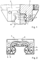
- a linear bearing according to the invention has a guide rail 1 which is partially surrounded by a support body 2 with a U-shaped cross section.
- raceways 3 for rolling elements 4 are formed on the two long sides of the guide rail 1 .
- the rolling elements are balls here.
- the support body 2 is supported on the guide rail 1 via them.
- the support body 2 therefore also has raceways 5 for the roller bodies 4.
- the roller bodies 4 are arranged in two endless rotations one above the other. Each revolution consists of a load-bearing area, a return area and two deflection areas for the rolling elements 4 which connect these areas to one another.
- the load-bearing areas are located on the raceways 3 of the guide rail and on the raceways 5 of the support body 2.
- the returning areas are each formed by a return bore 6 of the support body 2.
- deflection parts 7 are attached to the support body on the two end faces pointing in or against the direction of travel.
- roller bodies 4 Because when the support body 2 is separated from the guide rail 1, the roller bodies 4 must be held on the support body 2, so that a loss of roller bodies 4 during the transport of the support body 2 separately from the guide rail 1 or when mounting the support body 2 on the guide rail 1 is prevented becomes.
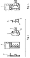
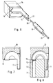
- Each deflection part 7 consists of a housing 9 for receiving deflection shells. These can either be in one piece, as shown in FIGS. 7 and 8, or, as shown in FIGS. 2 to 6, in two parts.
- the deflection shell 10 according to FIG. 7 has a projecting centering web 11 which projects into the support body 2 and also a projecting, annular, centering collar 12 which faces the support body 2 and is inserted into the return bore 6 of the support body 2.
- the return bore 6 has a countersink 13 at each of its ends.
- the deflection shell is divided into an outer deflection shell 14 and an inner deflection shell 15.
- the outer deflection shell contains the protruding centering web 11 and a centering collar half 16, while the other centering collar half 17 is formed on the inner deflection shell 15.
- the centering collar half 16 and the centering collar half 17 together the complete annular centering collar.
- the inner deflection shell 15 has a profiling 22 which is complementary to the outer deflection shell 14.
- the holding web 8 is located between the two aligned centering webs 11 of the corresponding deflection shells 10 and 14 of both end faces of the support body 2. It has the same cross-sectional shape as the centering webs 11 and integrates them. In order to fasten the holding web 8 between the centering webs 11, projecting plug pins 20 are attached to the holding web 8, which are inserted into recesses 21 of the centering webs 11 in a suitable manner.
- the holding web 8 is designed as a thin metal sheet strip with a constant cross section. To increase its rigidity, the sheet metal strip is deformed so that it has a bead 23 over its entire length. This starts from the side of the holding web 8 which faces away from the support body 2. To attach the retaining web 8 between the centering webs 11, the centering webs here also have recesses 21, in which the retaining web 8 is inserted with its ends in a suitable manner.
Landscapes
- Engineering & Computer Science (AREA)
- General Engineering & Computer Science (AREA)
- Mechanical Engineering (AREA)
- Bearings For Parts Moving Linearly (AREA)
Applications Claiming Priority (4)
| Application Number | Priority Date | Filing Date | Title |
|---|---|---|---|
| DE1996115722 DE19615722A1 (de) | 1996-04-20 | 1996-04-20 | Linearwälzlager |
| DE19615722 | 1996-04-20 | ||
| DE19643737 | 1996-10-23 | ||
| DE19643737A DE19643737A1 (de) | 1996-04-20 | 1996-10-23 | Linearwälzlager |
Publications (3)
| Publication Number | Publication Date |
|---|---|
| EP0802337A2 true EP0802337A2 (fr) | 1997-10-22 |
| EP0802337A3 EP0802337A3 (fr) | 1998-08-26 |
| EP0802337B1 EP0802337B1 (fr) | 2001-09-19 |
Family
ID=26024952
Family Applications (1)
| Application Number | Title | Priority Date | Filing Date |
|---|---|---|---|
| EP97102558A Expired - Lifetime EP0802337B1 (fr) | 1996-04-20 | 1997-02-18 | Palier linéaire à roulement |
Country Status (4)
| Country | Link |
|---|---|
| US (1) | US5727884A (fr) |
| EP (1) | EP0802337B1 (fr) |
| DE (2) | DE19643737A1 (fr) |
| ES (1) | ES2163054T3 (fr) |
Cited By (5)
| Publication number | Priority date | Publication date | Assignee | Title |
|---|---|---|---|---|
| EP0919738A1 (fr) * | 1997-11-29 | 1999-06-02 | INA Wälzlager Schaeffler oHG | Dispositif de lubrification pour un palier à roulement linéaire |
| EP0982509A1 (fr) * | 1998-08-27 | 2000-03-01 | Schneeberger Holding AG | Palier linéaire |
| WO2000015968A1 (fr) * | 1998-09-11 | 2000-03-23 | INA Wälzlager Schaeffler oHG | Palier a roulement lineaire |
| DE102007056855A1 (de) * | 2007-11-26 | 2009-05-28 | Robert Bosch Gmbh | Linearwälzlager mit versteiften Wälzkörperführungsfortsätzen |
| US10082174B2 (en) * | 2015-02-16 | 2018-09-25 | Thk Co., Ltd. | Movement guide device |
Families Citing this family (13)
| Publication number | Priority date | Publication date | Assignee | Title |
|---|---|---|---|---|
| DE10227727A1 (de) * | 2002-06-21 | 2004-01-08 | Ina-Schaeffler Kg | Linearwälzlager |
| DE10332922A1 (de) * | 2003-07-19 | 2005-02-03 | Ina-Schaeffler Kg | Führungswagen eines Linearwälzlagers |
| US7204036B2 (en) * | 2003-10-09 | 2007-04-17 | Nsk Ltd. | Linear guide apparatus |
| DE102005055101A1 (de) * | 2005-11-18 | 2007-05-24 | Bosch Rexroth Mechatronics Gmbh | Linearführungseinrichtung |
| KR101336353B1 (ko) | 2005-12-26 | 2013-12-04 | 티에치케이 가부시끼가이샤 | 운동 안내 장치 및 운동 안내 장치용 어태치먼트 |
| DE102007013945A1 (de) * | 2007-03-23 | 2008-09-25 | Schaeffler Kg | Schmiervorrichtung für ein Linearwälzlager |
| TWM434852U (en) * | 2011-11-17 | 2012-08-01 | Kuo-Le Tsao | Linear sliding block |
| JP5265793B1 (ja) * | 2012-03-13 | 2013-08-14 | Thk株式会社 | 転がり案内装置 |
| KR200468452Y1 (ko) | 2012-04-12 | 2013-08-13 | 에이엠에이 테크 코포레이션 | 선형 슬라이딩 블록 |
| US9163665B2 (en) * | 2013-09-27 | 2015-10-20 | Ome Technology Co., Ltd. | Linear guideway |
| JP6668652B2 (ja) * | 2015-09-18 | 2020-03-18 | 日本精工株式会社 | 直動案内装置、直動案内装置用エンドキャップ |
| CN112228455B (zh) * | 2019-07-15 | 2023-10-31 | Thk株式会社 | 运动引导装置以及在运动引导装置中使用的润滑路径部件 |
| TWI712749B (zh) * | 2020-08-05 | 2020-12-11 | 銀泰科技股份有限公司 | 具有入料口的扣具 |
Citations (1)
| Publication number | Priority date | Publication date | Assignee | Title |
|---|---|---|---|---|
| DE3527886A1 (de) | 1985-08-02 | 1987-04-30 | Star Gmbh | Waelzlager fuer linearbewegungen |
Family Cites Families (14)
| Publication number | Priority date | Publication date | Assignee | Title |
|---|---|---|---|---|
| US4502737A (en) * | 1981-11-18 | 1985-03-05 | Nippon Seiko Kabushiki Kaisha | Slide way bearing |
| DE3378780D1 (en) * | 1982-09-24 | 1989-02-02 | Tsubakimoto Precision Prod | Linear operation ball bearing |
| US4662763A (en) * | 1984-04-28 | 1987-05-05 | Tsubakimoto Precision Products Co., Ltd. | Tubular bearing for linear motion |
| JPS61136805A (ja) * | 1984-12-08 | 1986-06-24 | Nippon Seiko Kk | リニアガイド装置 |
| US4749284A (en) * | 1985-05-28 | 1988-06-07 | Hiroshi Teramachi | Linear sliding ball bearing |
| KR0182800B1 (ko) * | 1990-08-14 | 1999-05-15 | 쓰보이 우즈히고 | 직동형 가이드 장치 |
| JP2544663Y2 (ja) * | 1991-03-29 | 1997-08-20 | 日本トムソン株式会社 | 直動転がり案内ユニットの側板 |
| JPH0527407U (ja) * | 1991-09-25 | 1993-04-09 | 日本精工株式会社 | ボールねじ一体型直動案内ユニツト |
| DE4210299C2 (de) * | 1992-03-28 | 1995-09-28 | Schaeffler Waelzlager Kg | Wälzlager für eine geradlinige Bewegung |
| US5435649A (en) * | 1993-01-25 | 1995-07-25 | Nippon Thompson Co., Ltd. | Linear motion guide unit |
| DE4311515C2 (de) * | 1993-04-07 | 1999-02-04 | Star Gmbh | Wälzlager für Linearbewegungen |
| DE4331014C2 (de) * | 1993-08-12 | 1997-09-04 | Schaeffler Waelzlager Kg | Linearwälzlagerelement |
| DE4330772B4 (de) * | 1993-09-10 | 2013-02-14 | Robert Bosch Gmbh | Linearführungseinrichtung |
| DE29600917U1 (de) * | 1996-01-19 | 1996-03-07 | Hiwin Tech Corp | Hinsichtlich Druckbeanspruchung verstärkte lineare Kugelführung |
-
1996
- 1996-10-23 DE DE19643737A patent/DE19643737A1/de not_active Withdrawn
-
1997
- 1997-02-18 EP EP97102558A patent/EP0802337B1/fr not_active Expired - Lifetime
- 1997-02-18 DE DE59704635T patent/DE59704635D1/de not_active Expired - Lifetime
- 1997-02-18 ES ES97102558T patent/ES2163054T3/es not_active Expired - Lifetime
- 1997-04-11 US US08/840,308 patent/US5727884A/en not_active Expired - Lifetime
Patent Citations (1)
| Publication number | Priority date | Publication date | Assignee | Title |
|---|---|---|---|---|
| DE3527886A1 (de) | 1985-08-02 | 1987-04-30 | Star Gmbh | Waelzlager fuer linearbewegungen |
Cited By (6)
| Publication number | Priority date | Publication date | Assignee | Title |
|---|---|---|---|---|
| EP0919738A1 (fr) * | 1997-11-29 | 1999-06-02 | INA Wälzlager Schaeffler oHG | Dispositif de lubrification pour un palier à roulement linéaire |
| EP0982509A1 (fr) * | 1998-08-27 | 2000-03-01 | Schneeberger Holding AG | Palier linéaire |
| US6210040B1 (en) | 1998-08-27 | 2001-04-03 | Schneeberger Holding Ag | Linear-movement guide |
| WO2000015968A1 (fr) * | 1998-09-11 | 2000-03-23 | INA Wälzlager Schaeffler oHG | Palier a roulement lineaire |
| DE102007056855A1 (de) * | 2007-11-26 | 2009-05-28 | Robert Bosch Gmbh | Linearwälzlager mit versteiften Wälzkörperführungsfortsätzen |
| US10082174B2 (en) * | 2015-02-16 | 2018-09-25 | Thk Co., Ltd. | Movement guide device |
Also Published As
| Publication number | Publication date |
|---|---|
| EP0802337B1 (fr) | 2001-09-19 |
| US5727884A (en) | 1998-03-17 |
| ES2163054T3 (es) | 2002-01-16 |
| DE19643737A1 (de) | 1998-04-30 |
| EP0802337A3 (fr) | 1998-08-26 |
| DE59704635D1 (de) | 2001-10-25 |
Similar Documents
| Publication | Publication Date | Title |
|---|---|---|
| EP0802337B1 (fr) | Palier linéaire à roulement | |
| DE2945594C2 (de) | Linearlager mit vier Kugelumläufen | |
| EP0211243B1 (fr) | Palier à roulement pour mouvements linéaires | |
| DE69725407T3 (de) | Linear wälzführung | |
| DE60117174T2 (de) | Linearlagersegment | |
| DE3416207A1 (de) | Linear-kugellageranordnung | |
| DE4041269A1 (de) | Waelzlager fuer linearbewegungen | |
| DE3540099A1 (de) | Lineares gleitrollenlager | |
| DE3304783A1 (de) | Linearlager-baugruppe | |
| DE3447620C2 (de) | Linearwälzlager | |
| DE3527886A1 (de) | Waelzlager fuer linearbewegungen | |
| DE102019127288A1 (de) | Zweiteiliger Lagerkäfig sowie Wälzlager mit einem solchen Lagerkäfig | |
| WO2000008344A1 (fr) | Chariot de dispositif de guidage lineaire | |
| EP1619401A1 (fr) | Unité de guidage linéaire | |
| EP0601028B1 (fr) | Palier a roulement pour mouvement lineaire | |
| DE4133310A1 (de) | Waelzlager-geradefuehrungseinheit mit vier endlosen waelzlagerelement-umlaufwegen | |
| DE3418621A1 (de) | Waelzlager | |
| EP0692646B1 (fr) | Roulement linéaire | |
| EP1308641B1 (fr) | Chariot de guidage pour glissières profilées | |
| EP1516129B1 (fr) | Roulement a rouleaux lineaire | |
| EP1516128B1 (fr) | Palier a roulement lineaire | |
| EP1381787B1 (fr) | Element de palier pour glissiere lineaire | |
| DE19615722A1 (de) | Linearwälzlager | |
| EP1303706B1 (fr) | Roulement lineaire | |
| DE10227712B4 (de) | Linearwälzlager |
Legal Events
| Date | Code | Title | Description |
|---|---|---|---|
| PUAI | Public reference made under article 153(3) epc to a published international application that has entered the european phase |
Free format text: ORIGINAL CODE: 0009012 |
|
| 17P | Request for examination filed |
Effective date: 19970218 |
|
| AK | Designated contracting states |
Kind code of ref document: A2 Designated state(s): CH DE ES FR GB IT LI |
|
| RAP1 | Party data changed (applicant data changed or rights of an application transferred) |
Owner name: INA WAELZLAGER SCHAEFFLER OHG |
|
| PUAL | Search report despatched |
Free format text: ORIGINAL CODE: 0009013 |
|
| AK | Designated contracting states |
Kind code of ref document: A3 Designated state(s): CH DE ES FR GB IT LI |
|
| GRAG | Despatch of communication of intention to grant |
Free format text: ORIGINAL CODE: EPIDOS AGRA |
|
| GRAG | Despatch of communication of intention to grant |
Free format text: ORIGINAL CODE: EPIDOS AGRA |
|
| GRAH | Despatch of communication of intention to grant a patent |
Free format text: ORIGINAL CODE: EPIDOS IGRA |
|
| 17Q | First examination report despatched |
Effective date: 20010308 |
|
| GRAH | Despatch of communication of intention to grant a patent |
Free format text: ORIGINAL CODE: EPIDOS IGRA |
|
| GRAA | (expected) grant |
Free format text: ORIGINAL CODE: 0009210 |
|
| AK | Designated contracting states |
Kind code of ref document: B1 Designated state(s): CH DE ES FR GB IT LI |
|
| REG | Reference to a national code |
Ref country code: CH Ref legal event code: NV Representative=s name: TROESCH SCHEIDEGGER WERNER AG Ref country code: CH Ref legal event code: EP |
|
| REF | Corresponds to: |
Ref document number: 59704635 Country of ref document: DE Date of ref document: 20011025 |
|
| REG | Reference to a national code |
Ref country code: GB Ref legal event code: IF02 |
|
| GBT | Gb: translation of ep patent filed (gb section 77(6)(a)/1977) |
Effective date: 20011201 |
|
| REG | Reference to a national code |
Ref country code: ES Ref legal event code: FG2A Ref document number: 2163054 Country of ref document: ES Kind code of ref document: T3 |
|
| ET | Fr: translation filed | ||
| PLBE | No opposition filed within time limit |
Free format text: ORIGINAL CODE: 0009261 |
|
| STAA | Information on the status of an ep patent application or granted ep patent |
Free format text: STATUS: NO OPPOSITION FILED WITHIN TIME LIMIT |
|
| RAP2 | Party data changed (patent owner data changed or rights of a patent transferred) |
Owner name: INA-SCHAEFFLER KG |
|
| 26N | No opposition filed | ||
| REG | Reference to a national code |
Ref country code: CH Ref legal event code: PUE Owner name: INA WAELZLAGER SCHAEFFLER OHG TRANSFER- INA-SCHAEF |
|
| REG | Reference to a national code |
Ref country code: CH Ref legal event code: NV Representative=s name: TROESCH SCHEIDEGGER WERNER AG |
|
| REG | Reference to a national code |
Ref country code: FR Ref legal event code: CD |
|
| REG | Reference to a national code |
Ref country code: GB Ref legal event code: 732E |
|
| REG | Reference to a national code |
Ref country code: GB Ref legal event code: 732E Free format text: REGISTERED BETWEEN 20110407 AND 20110413 |
|
| REG | Reference to a national code |
Ref country code: DE Ref legal event code: R081 Ref document number: 59704635 Country of ref document: DE Owner name: SCHAEFFLER TECHNOLOGIES GMBH & CO. KG, DE Free format text: FORMER OWNER: SCHAEFFLER TECHNOLOGIES GMBH & CO. KG, 91074 HERZOGENAURACH, DE Effective date: 20120828 Ref country code: DE Ref legal event code: R081 Ref document number: 59704635 Country of ref document: DE Owner name: SCHAEFFLER TECHNOLOGIES AG & CO. KG, DE Free format text: FORMER OWNER: SCHAEFFLER TECHNOLOGIES GMBH & CO. KG, 91074 HERZOGENAURACH, DE Effective date: 20120828 |
|
| REG | Reference to a national code |
Ref country code: CH Ref legal event code: PFA Owner name: SCHAEFFLER TECHNOLOGIES AG AND CO. KG, DE Free format text: FORMER OWNER: INA-SCHAEFFLER KG, DE |
|
| REG | Reference to a national code |
Ref country code: DE Ref legal event code: R081 Ref document number: 59704635 Country of ref document: DE Owner name: SCHAEFFLER TECHNOLOGIES AG & CO. KG, DE Free format text: FORMER OWNER: SCHAEFFLER TECHNOLOGIES AG & CO. KG, 91074 HERZOGENAURACH, DE Effective date: 20140218 Ref country code: DE Ref legal event code: R081 Ref document number: 59704635 Country of ref document: DE Owner name: SCHAEFFLER TECHNOLOGIES GMBH & CO. KG, DE Free format text: FORMER OWNER: SCHAEFFLER TECHNOLOGIES AG & CO. KG, 91074 HERZOGENAURACH, DE Effective date: 20140218 |
|
| REG | Reference to a national code |
Ref country code: CH Ref legal event code: PFUS Owner name: SCHAEFFLER TECHNOLOGIES GMBH AND CO. KG, DE Free format text: FORMER OWNER: SCHAEFFLER TECHNOLOGIES AG AND CO. KG, DE |
|
| REG | Reference to a national code |
Ref country code: FR Ref legal event code: PLFP Year of fee payment: 19 |
|
| REG | Reference to a national code |
Ref country code: DE Ref legal event code: R081 Ref document number: 59704635 Country of ref document: DE Owner name: SCHAEFFLER TECHNOLOGIES AG & CO. KG, DE Free format text: FORMER OWNER: SCHAEFFLER TECHNOLOGIES GMBH & CO. KG, 91074 HERZOGENAURACH, DE Effective date: 20150210 |
|
| REG | Reference to a national code |
Ref country code: CH Ref legal event code: PFA Owner name: SCHAEFFLER TECHNOLOGIES AG AND CO. KG, DE Free format text: FORMER OWNER: SCHAEFFLER TECHNOLOGIES GMBH AND CO. KG, DE |
|
| PGFP | Annual fee paid to national office [announced via postgrant information from national office to epo] |
Ref country code: IT Payment date: 20150220 Year of fee payment: 19 |
|
| REG | Reference to a national code |
Ref country code: ES Ref legal event code: PC2A Owner name: SCHAEFFLER TECHNOLOGIES AG & CO.KG Effective date: 20150512 |
|
| PGFP | Annual fee paid to national office [announced via postgrant information from national office to epo] |
Ref country code: GB Payment date: 20150227 Year of fee payment: 19 Ref country code: FR Payment date: 20150227 Year of fee payment: 19 |
|
| PGFP | Annual fee paid to national office [announced via postgrant information from national office to epo] |
Ref country code: CH Payment date: 20160225 Year of fee payment: 20 Ref country code: ES Payment date: 20160321 Year of fee payment: 20 |
|
| PGFP | Annual fee paid to national office [announced via postgrant information from national office to epo] |
Ref country code: DE Payment date: 20160502 Year of fee payment: 20 |
|
| GBPC | Gb: european patent ceased through non-payment of renewal fee |
Effective date: 20160218 |
|
| REG | Reference to a national code |
Ref country code: FR Ref legal event code: ST Effective date: 20161028 |
|
| PG25 | Lapsed in a contracting state [announced via postgrant information from national office to epo] |
Ref country code: IT Free format text: LAPSE BECAUSE OF NON-PAYMENT OF DUE FEES Effective date: 20160218 |
|
| PG25 | Lapsed in a contracting state [announced via postgrant information from national office to epo] |
Ref country code: GB Free format text: LAPSE BECAUSE OF NON-PAYMENT OF DUE FEES Effective date: 20160218 Ref country code: FR Free format text: LAPSE BECAUSE OF NON-PAYMENT OF DUE FEES Effective date: 20160229 |
|
| REG | Reference to a national code |
Ref country code: DE Ref legal event code: R071 Ref document number: 59704635 Country of ref document: DE |
|
| REG | Reference to a national code |
Ref country code: CH Ref legal event code: PL |
|
| REG | Reference to a national code |
Ref country code: ES Ref legal event code: FD2A Effective date: 20170526 |
|
| PG25 | Lapsed in a contracting state [announced via postgrant information from national office to epo] |
Ref country code: ES Free format text: LAPSE BECAUSE OF EXPIRATION OF PROTECTION Effective date: 20170219 |