EP0802337A2 - Linear rolling bearing - Google Patents
Linear rolling bearing Download PDFInfo
- Publication number
- EP0802337A2 EP0802337A2 EP97102558A EP97102558A EP0802337A2 EP 0802337 A2 EP0802337 A2 EP 0802337A2 EP 97102558 A EP97102558 A EP 97102558A EP 97102558 A EP97102558 A EP 97102558A EP 0802337 A2 EP0802337 A2 EP 0802337A2
- Authority
- EP
- European Patent Office
- Prior art keywords
- deflection
- centering
- shell
- support body
- roller bearing
- Prior art date
- Legal status (The legal status is an assumption and is not a legal conclusion. Google has not performed a legal analysis and makes no representation as to the accuracy of the status listed.)
- Granted
Links
Images


Classifications
-
- F—MECHANICAL ENGINEERING; LIGHTING; HEATING; WEAPONS; BLASTING
- F16—ENGINEERING ELEMENTS AND UNITS; GENERAL MEASURES FOR PRODUCING AND MAINTAINING EFFECTIVE FUNCTIONING OF MACHINES OR INSTALLATIONS; THERMAL INSULATION IN GENERAL
- F16C—SHAFTS; FLEXIBLE SHAFTS; ELEMENTS OR CRANKSHAFT MECHANISMS; ROTARY BODIES OTHER THAN GEARING ELEMENTS; BEARINGS
- F16C29/00—Bearings for parts moving only linearly
- F16C29/04—Ball or roller bearings
- F16C29/06—Ball or roller bearings in which the rolling bodies circulate partly without carrying load
- F16C29/0633—Ball or roller bearings in which the rolling bodies circulate partly without carrying load with a bearing body defining a U-shaped carriage, i.e. surrounding a guide rail or track on three sides
- F16C29/0635—Ball or roller bearings in which the rolling bodies circulate partly without carrying load with a bearing body defining a U-shaped carriage, i.e. surrounding a guide rail or track on three sides whereby the return paths are provided as bores in a main body of the U-shaped carriage, e.g. the main body of the U-shaped carriage is a single part with end caps provided at each end
- F16C29/0638—Ball or roller bearings in which the rolling bodies circulate partly without carrying load with a bearing body defining a U-shaped carriage, i.e. surrounding a guide rail or track on three sides whereby the return paths are provided as bores in a main body of the U-shaped carriage, e.g. the main body of the U-shaped carriage is a single part with end caps provided at each end with balls
- F16C29/0642—Ball or roller bearings in which the rolling bodies circulate partly without carrying load with a bearing body defining a U-shaped carriage, i.e. surrounding a guide rail or track on three sides whereby the return paths are provided as bores in a main body of the U-shaped carriage, e.g. the main body of the U-shaped carriage is a single part with end caps provided at each end with balls with four rows of balls
- F16C29/0645—Ball or roller bearings in which the rolling bodies circulate partly without carrying load with a bearing body defining a U-shaped carriage, i.e. surrounding a guide rail or track on three sides whereby the return paths are provided as bores in a main body of the U-shaped carriage, e.g. the main body of the U-shaped carriage is a single part with end caps provided at each end with balls with four rows of balls with load directions in O-arrangement
-
- F—MECHANICAL ENGINEERING; LIGHTING; HEATING; WEAPONS; BLASTING
- F16—ENGINEERING ELEMENTS AND UNITS; GENERAL MEASURES FOR PRODUCING AND MAINTAINING EFFECTIVE FUNCTIONING OF MACHINES OR INSTALLATIONS; THERMAL INSULATION IN GENERAL
- F16C—SHAFTS; FLEXIBLE SHAFTS; ELEMENTS OR CRANKSHAFT MECHANISMS; ROTARY BODIES OTHER THAN GEARING ELEMENTS; BEARINGS
- F16C29/00—Bearings for parts moving only linearly
- F16C29/04—Ball or roller bearings
- F16C29/06—Ball or roller bearings in which the rolling bodies circulate partly without carrying load
- F16C29/0602—Details of the bearing body or carriage or parts thereof, e.g. methods for manufacturing or assembly
- F16C29/0604—Details of the bearing body or carriage or parts thereof, e.g. methods for manufacturing or assembly of the load bearing section
- F16C29/0607—Details of the bearing body or carriage or parts thereof, e.g. methods for manufacturing or assembly of the load bearing section of parts or members for retaining the rolling elements, i.e. members to prevent the rolling elements from falling out of the bearing body or carriage
-
- F—MECHANICAL ENGINEERING; LIGHTING; HEATING; WEAPONS; BLASTING
- F16—ENGINEERING ELEMENTS AND UNITS; GENERAL MEASURES FOR PRODUCING AND MAINTAINING EFFECTIVE FUNCTIONING OF MACHINES OR INSTALLATIONS; THERMAL INSULATION IN GENERAL
- F16C—SHAFTS; FLEXIBLE SHAFTS; ELEMENTS OR CRANKSHAFT MECHANISMS; ROTARY BODIES OTHER THAN GEARING ELEMENTS; BEARINGS
- F16C29/00—Bearings for parts moving only linearly
- F16C29/04—Ball or roller bearings
- F16C29/06—Ball or roller bearings in which the rolling bodies circulate partly without carrying load
- F16C29/0602—Details of the bearing body or carriage or parts thereof, e.g. methods for manufacturing or assembly
- F16C29/0609—Details of the bearing body or carriage or parts thereof, e.g. methods for manufacturing or assembly of the ends of the bearing body or carriage where the rolling elements change direction, e.g. end caps
-
- F—MECHANICAL ENGINEERING; LIGHTING; HEATING; WEAPONS; BLASTING
- F16—ENGINEERING ELEMENTS AND UNITS; GENERAL MEASURES FOR PRODUCING AND MAINTAINING EFFECTIVE FUNCTIONING OF MACHINES OR INSTALLATIONS; THERMAL INSULATION IN GENERAL
- F16C—SHAFTS; FLEXIBLE SHAFTS; ELEMENTS OR CRANKSHAFT MECHANISMS; ROTARY BODIES OTHER THAN GEARING ELEMENTS; BEARINGS
- F16C33/00—Parts of bearings; Special methods for making bearings or parts thereof
- F16C33/30—Parts of ball or roller bearings
- F16C33/66—Special parts or details in view of lubrication
Definitions
- the invention relates to a linear roller bearing with a fixed guide rail and a U-shaped support body which is supported on the guide rail via rolling elements and can be moved along this, the rolling elements arranged on both sides of the guide rail on the supporting body in rows arranged in an endless manner and are held there with retaining webs, roll on raceways of the guide rail and the support body, are deflected at the end faces of the support body pointing in the direction of travel and run back through return bores in the support body, deflection parts being arranged on the end faces of the support body, the molded parts in the Have webs protruding in the region of the raceways.
- a displacement of a deflection part can result in increases in the displacement resistance and the displacement force pulsation or even in the breakage of the roller deflection.
- the causes of this problem are that external impacts on the bearing system are passed on directly to the rolling element deflection and that a tolerance-related offset of the various rolling element raceways to the desired position occurs.
- each deflecting part has two projecting retaining webs which run in the support body and which adjoin one another with their free ends and are connected to one another by a common insertion pin. Because each deflecting part has an integral shape, neither a tolerance-related nor a shock-related offset of the rolling element deflection can be avoided here.
- retaining webs which can be designed as profiled plastic webs and molded directly on the deflection and each extend on half of the support body, there is a long demolding path of the deflection shell, so that it is very expensive.
- an associated tool for producing the deflection shell is required for each support body length.
- the invention has for its object to improve the function of the linear roller bearing and to make it less sensitive to external shock loads. Where possible, space should also be saved.
- the use of several expensive injection molds should be avoided in the manufacture of the linear roller bearing. Production-related fluctuations in the length of the support body should be compensated for.
- the retaining webs and with them the entire support body should have a high degree of rigidity with little installation space required.
- each deflecting part is formed by a housing and two deflecting shells inserted therein with play, on which the webs projecting into the supporting areas of the rolling elements are designed as centering webs, and in that each deflecting shell additionally has a projecting centering collar which a return bore of the support body protrudes.
- the two rolling element deflections for each long side of the guide rail and the adjacent rolling area of the supporting body are independent of one another. As a result, there is a tolerance dependence only in the case of the rolling element revolutions arranged one above the other. This is less critical due to the possible small distances between the rotations.
- the vertical distance between the rows of rolling elements from one another can be kept to a minimum.
- the deflecting shell can each be of split design, a part designated as the outer deflecting shell having the centering web and a centering collar half, while the other centering collar half is formed on a part designated as the inner deflection shell.
- the retaining web can each be arranged between two mutually facing centering webs of the two deflecting parts and inserted in their front-side recesses with plug pins.
- the retaining web can also be designed as a thin metal sheet strip.
- a retaining web can have a constant cross-section over its entire web length, so that the sheet metal strip can be made suitable for any supporting body length by simple cutting to length.
- the sheet metal strip can be connected to the deflection shells using a plug-in system. A bead extending in the longitudinal direction can be incorporated into the holding web. In this way, its rigidity can be increased significantly.
- connection points of the holding web with the two deflection shells lie in such an area that a smooth transition of the rolling elements from the load zone into the deflection zone is ensured.
- only one tool is required for the deflection shells and one profiling tool for the metal retaining web, since different support body lengths are made possible by a suitable cutting of the support web.
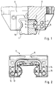
- a linear bearing according to the invention has a guide rail 1 which is partially surrounded by a support body 2 with a U-shaped cross section.
- raceways 3 for rolling elements 4 are formed on the two long sides of the guide rail 1 .
- the rolling elements are balls here.
- the support body 2 is supported on the guide rail 1 via them.
- the support body 2 therefore also has raceways 5 for the roller bodies 4.
- the roller bodies 4 are arranged in two endless rotations one above the other. Each revolution consists of a load-bearing area, a return area and two deflection areas for the rolling elements 4 which connect these areas to one another.
- the load-bearing areas are located on the raceways 3 of the guide rail and on the raceways 5 of the support body 2.
- the returning areas are each formed by a return bore 6 of the support body 2.
- deflection parts 7 are attached to the support body on the two end faces pointing in or against the direction of travel.
- roller bodies 4 Because when the support body 2 is separated from the guide rail 1, the roller bodies 4 must be held on the support body 2, so that a loss of roller bodies 4 during the transport of the support body 2 separately from the guide rail 1 or when mounting the support body 2 on the guide rail 1 is prevented becomes.
- Each deflection part 7 consists of a housing 9 for receiving deflection shells. These can either be in one piece, as shown in FIGS. 7 and 8, or, as shown in FIGS. 2 to 6, in two parts.
- the deflection shell 10 according to FIG. 7 has a projecting centering web 11 which projects into the support body 2 and also a projecting, annular, centering collar 12 which faces the support body 2 and is inserted into the return bore 6 of the support body 2.
- the return bore 6 has a countersink 13 at each of its ends.
- the deflection shell is divided into an outer deflection shell 14 and an inner deflection shell 15.
- the outer deflection shell contains the protruding centering web 11 and a centering collar half 16, while the other centering collar half 17 is formed on the inner deflection shell 15.
- the centering collar half 16 and the centering collar half 17 together the complete annular centering collar.
- the inner deflection shell 15 has a profiling 22 which is complementary to the outer deflection shell 14.
- the holding web 8 is located between the two aligned centering webs 11 of the corresponding deflection shells 10 and 14 of both end faces of the support body 2. It has the same cross-sectional shape as the centering webs 11 and integrates them. In order to fasten the holding web 8 between the centering webs 11, projecting plug pins 20 are attached to the holding web 8, which are inserted into recesses 21 of the centering webs 11 in a suitable manner.
- the holding web 8 is designed as a thin metal sheet strip with a constant cross section. To increase its rigidity, the sheet metal strip is deformed so that it has a bead 23 over its entire length. This starts from the side of the holding web 8 which faces away from the support body 2. To attach the retaining web 8 between the centering webs 11, the centering webs here also have recesses 21, in which the retaining web 8 is inserted with its ends in a suitable manner.
Landscapes
- Engineering & Computer Science (AREA)
- General Engineering & Computer Science (AREA)
- Mechanical Engineering (AREA)
- Bearings For Parts Moving Linearly (AREA)
Abstract
Description
Die Erfindung betrifft ein Linearwälzlager mit einer festen Führungsschiene und einem diese U-förmig umgreifenden Tragkörper, welcher sich über Wälzkörper an der Führungsschiene abstützt und längs dieser verfahrbar ist, wobei die Wälzkörper zu beiden Seiten der Führungsschiene an dem Tragkörper in paarweise angeordneten Reihen endlos umlaufend angeordnet und dort mit Haltestegen gehalten sind, sich an Laufbahnen der Führungsschiene und des Tragkörpers abwälzen, an den in Fahrtrichtung weisenden Stirnseiten des Tragkörpers umgelenkt werden und durch Rücklaufbohrungen des Tragkörpers hindurch zurücklaufen, wobei an den Stirnseiten des Tragkörpers Umlenkteile angeordnet sind, die angeformte, in den Bereich der Laufbahnen hineinragende Stege aufweisen.The invention relates to a linear roller bearing with a fixed guide rail and a U-shaped support body which is supported on the guide rail via rolling elements and can be moved along this, the rolling elements arranged on both sides of the guide rail on the supporting body in rows arranged in an endless manner and are held there with retaining webs, roll on raceways of the guide rail and the support body, are deflected at the end faces of the support body pointing in the direction of travel and run back through return bores in the support body, deflection parts being arranged on the end faces of the support body, the molded parts in the Have webs protruding in the region of the raceways.
Bei Linearwälzlagern kann eine Verlagerung eines Umlenkteils Erhöhungen des Verschiebewiderstandes und der Verschiebekraftpulsation zur Folge haben oder sogar zum Bruch der Wälzkörperumlenkung führen. Die Ursachen für dieses Problem liegen darin, daß äußere Schläge auf das Lagersystem direkt auf die Wälzkörperumlenkung weitergeleitet werden und daß ein toleranzbedingter Versatz der verschiedenen Wälzkörperlaufbahnen zur Sollposition auftritt.In the case of linear roller bearings, a displacement of a deflection part can result in increases in the displacement resistance and the displacement force pulsation or even in the breakage of the roller deflection. The causes of this problem are that external impacts on the bearing system are passed on directly to the rolling element deflection and that a tolerance-related offset of the various rolling element raceways to the desired position occurs.
Aus der DE-OS 35 27 886 ist ein Linearwälzlager der eingangs genannten Art bekannt, bei welchem die beiden Umlenkteile jeweils einstückig ausgeführt sind. Jedes Umlenkteil weist zwei abstehende, in dem Tragkörper verlaufende Haltestege auf, die mit ihren freien Ende aneinander angrenzen und durch einen gemeinsamen Einsteckstift miteinander verbunden sind. Dadurch, daß jedes Umlenkteil eine einstückige Form hat, kann hier weder ein toleranzbedingter noch ein stoßbedingter Versatz der Wälzkörperumlenkung vermieden werden.From DE-OS 35 27 886 a linear roller bearing of the type mentioned is known, in which the two deflecting parts are each made in one piece. Each deflecting part has two projecting retaining webs which run in the support body and which adjoin one another with their free ends and are connected to one another by a common insertion pin. Because each deflecting part has an integral shape, neither a tolerance-related nor a shock-related offset of the rolling element deflection can be avoided here.
Bei einer Wälzkörper-Rückhaltung durch Haltestege, die als profilierte Kunststoffstege ausgeführt und direkt an der Umlenkung angespritzt sein können und sich jeweils auf der Hälfte des Tragkörpers erstrecken, ergibt sich ein langer Entformungsweg der Umlenkschale, so daß diese sehr teuer wird. Außerdem benötigt man hier für jede Tragkörperlänge ein zugehöriges Werkzeug zur Herstellung der Umlenkschale.With rolling element retention by retaining webs, which can be designed as profiled plastic webs and molded directly on the deflection and each extend on half of the support body, there is a long demolding path of the deflection shell, so that it is very expensive. In addition, an associated tool for producing the deflection shell is required for each support body length.
Der Erfindung liegt die Aufgabe zugrunde, die Funktion des Linearwälzlagers zu verbessern und dieses unempfindlicher gegenüber äußeren stoßartigen Belastungen zu machen. Dabei soll nach Möglichkeit auch eine Bauraumeinsparung erfolgen. Bei der Herstellung des Linearwälzlagers soll die Verwendung mehrerer teuerer Spritzwerkzeuge vermieden werden. Fertigungstechnisch bedingte Schwankungen der Tragkörperlänge sollen ausgeglichen werden. Dabei sollen die Haltestege und mit diesen der gesamte Tragkörper bei geringem erforderlichen Bauraum eine hohe Steifigkeit erhalten.The invention has for its object to improve the function of the linear roller bearing and to make it less sensitive to external shock loads. Where possible, space should also be saved. The use of several expensive injection molds should be avoided in the manufacture of the linear roller bearing. Production-related fluctuations in the length of the support body should be compensated for. The retaining webs and with them the entire support body should have a high degree of rigidity with little installation space required.
Diese Aufgabe wird erfindungsgemäß dadurch gelöst, daß jedes Umlenkteil von einem Gehäuse und zwei darin mit Spiel eingesetzten Umlenkschalen gebildet ist, an welchen die in die Tragbereiche der Wälzkörper hineinragenden Stege als Zentrierstege ausgebildet sind, und daß jede Umlenkschale zusätzlich einen abstehenden Zentrierbund aufweist, der in eine Rücklaufbohrung des Tragkörpers hineinragt. Infolge des Spiels zwischen den Umlenkschalen und deren Gehäusen ist das Lager unempfindlich gegenüber äußeren Stößen. Dadurch, daß die Umlenkschalen jeweils mit ihrem Zentrierbund in die Rücklaufbohrung des Tragkörpers und gleichzeitig mit ihrem Zentriersteg in den Laufbahnbereich greift, ergibt sich ein exakter Sitz der Umlenkung hinsichtlich der Laufbahnen und der Rücklaufbohrungen. Infolge dieser Anordnung sind nur noch horizontale Abweichungen in geringem Maße möglich.This object is achieved in that each deflecting part is formed by a housing and two deflecting shells inserted therein with play, on which the webs projecting into the supporting areas of the rolling elements are designed as centering webs, and in that each deflecting shell additionally has a projecting centering collar which a return bore of the support body protrudes. As a result of the game between the deflection shells and their The housing is insensitive to external shocks. The fact that the deflection shells each engage with their centering collar in the return bore of the support body and at the same time with their centering web in the raceway area, results in an exact fit of the deflection with respect to the raceways and the return bores. As a result of this arrangement, only small horizontal deviations are possible.
Die beiden Wälzkörperumlenkungen für jede Längsseite der Führungsschiene und den benachbarten Abrollbereich des Tragkörpers sind voneinander unabhängig. Dadurch besteht eine Toleranzabhängigkeit jeweils nur bei den übereinander angeordneten Wälzkörperumläufen einer Seite. Diese ist infolge der möglichen geringen Abstände der Umläufe voneinander weniger kritisch. Der vertikale Abstand der Wälzkörperreihen voneinander kann minimal gehalten werden.The two rolling element deflections for each long side of the guide rail and the adjacent rolling area of the supporting body are independent of one another. As a result, there is a tolerance dependence only in the case of the rolling element revolutions arranged one above the other. This is less critical due to the possible small distances between the rotations. The vertical distance between the rows of rolling elements from one another can be kept to a minimum.
Die Umlenkschale kann jeweils geteilt ausgeführt sein, wobei ein als äußere Umlenkschale bezeichneter Teil den Zentriersteg und eine Zentrierbundhälfte aufweist, während an einem als innere Umlenkschale bezeichneten Teil die andere Zentrierbundhälfte ausgebildet ist.The deflecting shell can each be of split design, a part designated as the outer deflecting shell having the centering web and a centering collar half, while the other centering collar half is formed on a part designated as the inner deflection shell.
Der Haltesteg kann jeweils zwischen zwei einander zugewandten fluchtenden Zentrierstegen der beiden Umlenkteile angeordnet und in deren stirnseitigen Ausnehmungen mit Steckzapfen passend eingesteckt sein.The retaining web can each be arranged between two mutually facing centering webs of the two deflecting parts and inserted in their front-side recesses with plug pins.
Der Haltesteg kann auch jeweils als dünner metallischer Blechstreifen ausgebildet sein. Ein solcher Haltesteg kann auf seiner gesamten Steglänge einen konstanten Querschnitt aufweisen, so daß der Blechstreifen durch einfaches Ablängen für jede beliebige Tragkörperlänge geeignet gemacht werden kann. Die Verbindung des Blechstreifens mit den Umlenkschalen kann über ein Stecksystem erfolgen. In den Haltesteg kann eine in Längsrichtung sich erstreckende Sicke eingearbeitet sein. Auf diese Weise läßt sich seine Steifigkeit wesentlich erhöhen.The retaining web can also be designed as a thin metal sheet strip. Such a retaining web can have a constant cross-section over its entire web length, so that the sheet metal strip can be made suitable for any supporting body length by simple cutting to length. The sheet metal strip can be connected to the deflection shells using a plug-in system. A bead extending in the longitudinal direction can be incorporated into the holding web. In this way, its rigidity can be increased significantly.
Mit einer solchen Ausführung sind folgende Vorteile erzielbar: Durch die Verwendung eines dünnen, eventuell profilierten metallischen Blechstreifens ergibt sich auf kleinem Bauraum eine sehr steife Vorrichtung für die Wälzkörper-Rückhaltung. Dabei sind die Umlenkschalen von dem Rückhaltebereich getrennt. Der Haltesteg ist von Längentoleranzen des Tragkörpers unabhängig, da er im Stecksystem mit Spiel angeordnet ist. Auf diese Weise kann eine Verspannung, welche die Funktion eines Haltesteges beeinträchtigen könnte, nicht auftreten.The following advantages can be achieved with such a design: The use of a thin, possibly profiled metal sheet strip results in a very rigid device for rolling element retention in a small installation space. The deflection shells are separated from the retention area. The retaining web is independent of the length tolerances of the supporting body, since it is arranged with play in the plug-in system. In this way, tension that could impair the function of a holding bridge cannot occur.
Die Verbindungsstellen des Haltesteges mit den beiden Umlenkschalen liegen bei der Montage des Tragkörpers an der Führungsschiene in einem solchen Bereich, daß ein stoßfreier Übergang der Wälzkörper von der Lastzone in die Umlenkzone gewährleistet ist. Für verschiedene Tragkörperlängen wird nur ein Werkzeug für die Umlenkschalen und ein Profilierwerkzeug für den metallischen Haltesteg benötigt, da verschiedene Tragkörperlängen jeweils durch ein passendes Ablängen des Haltesteges ermöglicht werden.When the support body is mounted on the guide rail, the connection points of the holding web with the two deflection shells lie in such an area that a smooth transition of the rolling elements from the load zone into the deflection zone is ensured. For different support body lengths, only one tool is required for the deflection shells and one profiling tool for the metal retaining web, since different support body lengths are made possible by a suitable cutting of the support web.
Ausführungsbeispiele der Erfindung sind in den Zeichnungen dargestellt und werden im folgenden näher beschrieben. Es zeigen:
- Figur 1
- einen an einer Führungsschiene angeordneten Tragkörper eines Linearwälzlagers, teilweise in stirnseitiger Ansicht und teilweise im Querschnitt;
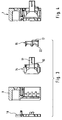
Figur 2- eine Innenansicht eines Umlenkteils;
Figur 3- eine explosionsartige Darstellung der Einzelteile des Umlenkteils im Längsschnitt bzw. in der Seitenansicht;
Figur 4- das zusammengesetzte Umlenkteil im Längsschnitt;
- Figur 5
- eine explosionsartige Darstellung der Einzelteile des Umlenkteils in der Innenansicht;
Figur 6- eine perspektivische Darstellung einer äußeren Umlenkschale;
Figur 7- eine abgewandelte Umlenkschale im waagerechten Schnitt;
Figur 8- eine abgewandelte Umlenkschale, die an einem Tragkörper montiert ist, im waagerechten Schnitt;
Figur 9- eine perspektivische Darstellung eines Haltesteges, der zwischen zwei äußeren, mit Zentrierstegen versehenen Umlenkschalen angeordnet ist, wobei jedoch zugehörige Zentrierbundhälften nicht dargestellt sind;
Figur 10- einen Querschnitt durch den Tragkörper eines Linearlagers, und zwar durch den Steckbereich des Zentriersteges einer äußeren Umlenkschale für den Wälzkörper-Haltesteg.
- Figure 1
- a support body of a linear roller bearing arranged on a guide rail, partly in an end view and partly in cross section;
- Figure 2
- an interior view of a deflecting part;
- Figure 3
- an exploded view of the individual parts of the deflecting part in longitudinal section or in side view;
- Figure 4
- the composite deflecting part in longitudinal section;
- Figure 5
- an exploded view of the individual parts of the deflecting part in the inside view;
- Figure 6
- a perspective view of an outer deflection shell;
- Figure 7
- a modified deflection shell in a horizontal section;
- Figure 8
- a modified deflection shell, which is mounted on a support body, in a horizontal section;
- Figure 9
- a perspective view of a retaining web, which is arranged between two outer, provided with centering deflection shells, but associated centering collar halves are not shown;
- Figure 10
- a cross section through the support body of a linear bearing, namely through the plug-in area of the centering web of an outer deflection shell for the rolling element holding web.
Ein erfindungsgemäßes Linearlager weist eine Führungsschiene 1 auf, welche von einem im Querschnitt U-förmigen Tragkörper 2 teilweise umfaßt wird. An den beiden Längsseiten der Führungsschiene 1 sind Laufbahnen 3 für Wälzkörper 4 ausgebildet. Die Wälzkörper sind hier Kugeln. Über sie stützt sich der Tragkörper 2 an der Führungsschiene 1 ab. Der Tragkörper 2 hat daher ebenfalls Laufbahnen 5 für die Wälzkörper 4. An jeder Längsseite der Führungsschiene 1 sind die Wälzkörper 4 in zwei übereinander befindlichen endlosen Umläufen angeordnet. Jeder Umlauf besteht aus einem tragenden Bereich, einen rücklaufenden Bereich und zwei diese Bereiche miteinander verbindenden Umlenkbereichen für die Wälzkörper 4.A linear bearing according to the invention has a guide rail 1 which is partially surrounded by a
Die tragenden Bereiche befinden sich an den Laufbahnen 3 der Führungsschiene und an den Laufbahnen 5 des Tragkörpers 2. Die rücklaufenden Bereiche werden jeweils von einer Rücklaufbohrung 6 des Tragkörpers 2 gebildet. Für die Umlenkbereiche sind an dem Tragkörper an den beiden in bzw. entgegen der Fahrtrichtung weisenden Stirnseiten Umlenkteile 7 angebracht. Zwischen den Wälzkörpern 4 des unteren Umlaufs und den Wälzkörpern 4 des oberen Umlaufes befindet sich im Bereich der Führungsschiene 1 jeweils ein Haltesteg 8, welcher dafür sorgt, daß die Wälzkörper 4 nicht aus dem Tragkörper 2 herausfallen, wenn dieser von der Führungsschiene 1 abgezogen wird. Denn bei Trennung des Tragkörpers 2 von der Führungsschiene 1 müssen die Wälzkörper 4 am Tragkörper 2 gehalten werden, so daß ein Verlust von Wälzkörpern 4 während des Transport des Tragkörpers 2 gesondert von der Führungsschiene 1 oder bei der Montage des Tragkörpers 2 an der Führungsschiene 1 verhindert wird.The load-bearing areas are located on the
Jedes Umlenkteil 7 besteht aus einem Gehäuse 9 zur Aufnahme von Umlenkschalen. Diese können entweder, wie in den Figuren 7 und 8 gezeigt, einstückig oder, wie in den Figuren 2 bis 6 gezeigt, zweiteilig ausgeführt sein. Die Umlenkschale 10 gemäß Figur 7 hat einen abstehenden, in den Tragkörper 2 hineinragenden Zentriersteg 11 und außerdem einen abstehenden, kreisringförmigen, zum Tragkörper 2 weisenden Zentrierbund 12, der in der Rücklaufbohrung 6 des Tragkörpers 2 eingesteckt ist. Zum Zweck der Zentrierung weist die Rücklaufbohrung 6 an ihren Enden jeweils eine Senkung 13 auf.Each
Aus Figur 3 erkennt man, daß in diesem Ausführungsbeispiel die Umlenkschale in eine äußere Umlenkschale 14 und eine innere Umlenkschale 15 aufgeteilt ist. Die äußere Umlenkschale enthält den abstehenden Zentriersteg 11 und eine Zentrierbundhälfte 16, während die andere Zentrierbundhälfte 17 an der inneren Umlenkschale 15 ausgebildet ist. Im zusammengesetzten Zustand, wenn die äußere Umlenkschale 14 und die innere Umlenkschale 15 in dem Gehäuse 9 eingesetzt sind, bilden die Zentrierbundhälfte 16 und die Zentrierbundhälfte 17 zusammen den vollständigen ringförmigen Zentrierbund. Im Umlenkbereich weist die innere Umlenkschale 15 eine Profilierung 22 auf, die komplementär zu der äußeren Umlenkschale 14 ausgebildet ist.From Figure 3 it can be seen that in this embodiment the deflection shell is divided into an
An dem Umlenkteil 7 befindet sich außerdem ein Frontabstreifer 18, welcher an der äußeren Stirnseite in das Gehäuse 9 eingesteckt ist. Innerhalb des Gehäuses 9 ist schließlich noch ein Schmierkanaleinsatz 19 angeordnet. Der Haltesteg 8 befindet sich jeweils zwischen den beiden fluchtenden Zentrierstegen 11 der einander entsprechenden Umlenkschalen 10 bzw. 14 beider Stirnseiten des Tragkörpers 2. Er hat dieselbe Querschnittsform wie die Zentrierstege 11 und integriert diese. Zur Befestigung des Haltesteges 8 zwischen den Zentrierstegen 11 sind am Haltesteg 8 abstehende Steckzapfen 20 angebracht, welche in Ausnehmungen 21 der Zentrierstege 11 passend eingesteckt sind.On the
In den Figuren 9 und 10 ist der Haltesteg 8 als dünner metallischer Blechstreifen mit konstantem Querschnitt ausgebildet. Zur Erhöhung seiner Steifigkeit ist der Blechstreifen so verformt, daß er auf seiner gesamten Länge eine Sicke 23 aufweist. Diese geht von der Seite des Haltesteges 8 aus, die von dem Tragkörper 2 abgewandt ist. Zur Befestigung des Haltesteges 8 zwischen den Zentrierstegen 11 weisen die Zentrierstege hier ebenfalls Ausnehmungen 21 auf, in welchen der Haltesteg 8 mit seinen Enden passend eingesteckt ist.In FIGS. 9 and 10, the holding
- 11
- FührungsschieneGuide rail
- 22nd
- TragkörperSupporting body
- 33rd
- Laufbahncareer
- 44th
- WälzkörperRolling elements
- 55
- Laufbahncareer
- 66
- RücklaufbohrungReturn hole
- 77
- UmlenkteilDeflecting part
- 88th
- HalteteilHolding part
- 99
- Gehäusecasing
- 1010th
- UmlenkschaleDeflection cup
- 1111
- ZentrierstegCentering bar
- 1212th
- ZentrierbundCentering collar
- 1313
- SenkungLowering
- 1414
- äußere Umlenkschaleouter deflection shell
- 1515
- innere Umlenkschaleinner deflection cup
- 1616
- ZentrierbundhälfteCenter collar half
- 1717th
- ZentrierbundhälfteCenter collar half
- 1818th
- FrontabstreiferFront wiper
- 1919th
- SchmierkanaleinsatzLubrication channel insert
- 2020th
- SteckzapfenSpigot
- 2121
- AusnehmungRecess
- 2222
- ProfilierungProfiling
- 2323
- SickeSurround
Claims (9)
Applications Claiming Priority (4)
| Application Number | Priority Date | Filing Date | Title |
|---|---|---|---|
| DE19615722 | 1996-04-20 | ||
| DE1996115722 DE19615722A1 (en) | 1996-04-20 | 1996-04-20 | Linear roller bearing |
| DE19643737 | 1996-10-23 | ||
| DE19643737A DE19643737A1 (en) | 1996-04-20 | 1996-10-23 | Linear roller bearings |
Publications (3)
| Publication Number | Publication Date |
|---|---|
| EP0802337A2 true EP0802337A2 (en) | 1997-10-22 |
| EP0802337A3 EP0802337A3 (en) | 1998-08-26 |
| EP0802337B1 EP0802337B1 (en) | 2001-09-19 |
Family
ID=26024952
Family Applications (1)
| Application Number | Title | Priority Date | Filing Date |
|---|---|---|---|
| EP97102558A Expired - Lifetime EP0802337B1 (en) | 1996-04-20 | 1997-02-18 | Linear rolling bearing |
Country Status (4)
| Country | Link |
|---|---|
| US (1) | US5727884A (en) |
| EP (1) | EP0802337B1 (en) |
| DE (2) | DE19643737A1 (en) |
| ES (1) | ES2163054T3 (en) |
Cited By (5)
| Publication number | Priority date | Publication date | Assignee | Title |
|---|---|---|---|---|
| EP0919738A1 (en) * | 1997-11-29 | 1999-06-02 | INA Wälzlager Schaeffler oHG | Lubrication device for a linear rolling bearing |
| EP0982509A1 (en) * | 1998-08-27 | 2000-03-01 | Schneeberger Holding AG | Linear motion guide |
| WO2000015968A1 (en) * | 1998-09-11 | 2000-03-23 | INA Wälzlager Schaeffler oHG | Linear roll bearing |
| DE102007056855A1 (en) * | 2007-11-26 | 2009-05-28 | Robert Bosch Gmbh | Guiding wagon for linear antifriction bearing, has rolling element line that is carried in endless rotating channel, where separate stabilization slat extends over entire length of carrying channel |
| US10082174B2 (en) * | 2015-02-16 | 2018-09-25 | Thk Co., Ltd. | Movement guide device |
Families Citing this family (13)
| Publication number | Priority date | Publication date | Assignee | Title |
|---|---|---|---|---|
| DE10227727A1 (en) * | 2002-06-21 | 2004-01-08 | Ina-Schaeffler Kg | linear bearings |
| DE10332922A1 (en) * | 2003-07-19 | 2005-02-03 | Ina-Schaeffler Kg | Slide for linear ball bearings has channel which supplies lubricant to balls and is fitted with valve with funnel sections and slits forming cross which can be closed to cut off flow of lubricant |
| US7204036B2 (en) * | 2003-10-09 | 2007-04-17 | Nsk Ltd. | Linear guide apparatus |
| DE102005055101A1 (en) * | 2005-11-18 | 2007-05-24 | Bosch Rexroth Mechatronics Gmbh | Linear guide device |
| WO2007074754A1 (en) * | 2005-12-26 | 2007-07-05 | Thk Co., Ltd. | Motion guide device and attachment for motion guide device |
| DE102007013945A1 (en) * | 2007-03-23 | 2008-09-25 | Schaeffler Kg | Lubricating device for a linear roller bearing |
| TWM434852U (en) * | 2011-11-17 | 2012-08-01 | Kuo-Le Tsao | Linear sliding block |
| JP5265793B1 (en) * | 2012-03-13 | 2013-08-14 | Thk株式会社 | Rolling guide device |
| KR200468452Y1 (en) | 2012-04-12 | 2013-08-13 | 에이엠에이 테크 코포레이션 | Linear sliding block |
| US9163665B2 (en) * | 2013-09-27 | 2015-10-20 | Ome Technology Co., Ltd. | Linear guideway |
| JP6668652B2 (en) * | 2015-09-18 | 2020-03-18 | 日本精工株式会社 | Linear motion guide device, end cap for linear motion guide device |
| CN112228455B (en) * | 2019-07-15 | 2023-10-31 | Thk株式会社 | Motion guide device and lubrication path member used in motion guide device |
| TWI712749B (en) * | 2020-08-05 | 2020-12-11 | 銀泰科技股份有限公司 | Buckle with inlet |
Citations (1)
| Publication number | Priority date | Publication date | Assignee | Title |
|---|---|---|---|---|
| DE3527886A1 (en) | 1985-08-02 | 1987-04-30 | Star Gmbh | Rolling-contact bearing for linear movements |
Family Cites Families (14)
| Publication number | Priority date | Publication date | Assignee | Title |
|---|---|---|---|---|
| US4502737A (en) * | 1981-11-18 | 1985-03-05 | Nippon Seiko Kabushiki Kaisha | Slide way bearing |
| US4582369A (en) * | 1982-09-24 | 1986-04-15 | Tsubakimoto Precision Products Co., Ltd. | Linear motion ball bearing |
| KR890002989B1 (en) * | 1984-04-28 | 1989-08-16 | 가부시끼 가이샤 쯔바끼모또 세이꼬오 | Tubular bearing for liner motion |
| JPS61136805A (en) * | 1984-12-08 | 1986-06-24 | Nippon Seiko Kk | Linear guide apparatus |
| US4749284A (en) * | 1985-05-28 | 1988-06-07 | Hiroshi Teramachi | Linear sliding ball bearing |
| KR0182800B1 (en) * | 1990-08-14 | 1999-05-15 | 쓰보이 우즈히고 | Linear guide device |
| JP2544663Y2 (en) * | 1991-03-29 | 1997-08-20 | 日本トムソン株式会社 | Side plate of linear motion rolling guide unit |
| JPH0527407U (en) * | 1991-09-25 | 1993-04-09 | 日本精工株式会社 | Ball screw integrated linear motion guide unit |
| DE4210299C2 (en) * | 1992-03-28 | 1995-09-28 | Schaeffler Waelzlager Kg | Rolling bearings for straight movement |
| US5435649A (en) * | 1993-01-25 | 1995-07-25 | Nippon Thompson Co., Ltd. | Linear motion guide unit |
| DE4311515C2 (en) * | 1993-04-07 | 1999-02-04 | Star Gmbh | Rolling bearings for linear movements |
| DE4331014C2 (en) * | 1993-08-12 | 1997-09-04 | Schaeffler Waelzlager Kg | Linear roller bearing element |
| DE4330772B4 (en) * | 1993-09-10 | 2013-02-14 | Robert Bosch Gmbh | Linear guide device |
| DE29600917U1 (en) * | 1996-01-19 | 1996-03-07 | Hiwin Tech Corp | Linear ball guide reinforced with regard to pressure |
-
1996
- 1996-10-23 DE DE19643737A patent/DE19643737A1/en not_active Withdrawn
-
1997
- 1997-02-18 ES ES97102558T patent/ES2163054T3/en not_active Expired - Lifetime
- 1997-02-18 EP EP97102558A patent/EP0802337B1/en not_active Expired - Lifetime
- 1997-02-18 DE DE59704635T patent/DE59704635D1/en not_active Expired - Lifetime
- 1997-04-11 US US08/840,308 patent/US5727884A/en not_active Expired - Lifetime
Patent Citations (1)
| Publication number | Priority date | Publication date | Assignee | Title |
|---|---|---|---|---|
| DE3527886A1 (en) | 1985-08-02 | 1987-04-30 | Star Gmbh | Rolling-contact bearing for linear movements |
Cited By (6)
| Publication number | Priority date | Publication date | Assignee | Title |
|---|---|---|---|---|
| EP0919738A1 (en) * | 1997-11-29 | 1999-06-02 | INA Wälzlager Schaeffler oHG | Lubrication device for a linear rolling bearing |
| EP0982509A1 (en) * | 1998-08-27 | 2000-03-01 | Schneeberger Holding AG | Linear motion guide |
| US6210040B1 (en) | 1998-08-27 | 2001-04-03 | Schneeberger Holding Ag | Linear-movement guide |
| WO2000015968A1 (en) * | 1998-09-11 | 2000-03-23 | INA Wälzlager Schaeffler oHG | Linear roll bearing |
| DE102007056855A1 (en) * | 2007-11-26 | 2009-05-28 | Robert Bosch Gmbh | Guiding wagon for linear antifriction bearing, has rolling element line that is carried in endless rotating channel, where separate stabilization slat extends over entire length of carrying channel |
| US10082174B2 (en) * | 2015-02-16 | 2018-09-25 | Thk Co., Ltd. | Movement guide device |
Also Published As
| Publication number | Publication date |
|---|---|
| EP0802337A3 (en) | 1998-08-26 |
| US5727884A (en) | 1998-03-17 |
| EP0802337B1 (en) | 2001-09-19 |
| DE19643737A1 (en) | 1998-04-30 |
| DE59704635D1 (en) | 2001-10-25 |
| ES2163054T3 (en) | 2002-01-16 |
Similar Documents
| Publication | Publication Date | Title |
|---|---|---|
| EP0802337B1 (en) | Linear rolling bearing | |
| DE2945594C2 (en) | Linear bearing with four ball circuits | |
| EP0211243B1 (en) | Rolling-contact bearing for linear movement | |
| DE69725407T3 (en) | LINEAR ROLLING GUIDE | |
| DE60117174T2 (en) | LINEAR BEARING SEGMENT | |
| DE3416207A1 (en) | LINEAR BALL BEARING ARRANGEMENT | |
| DE4041269A1 (en) | ROLLER BEARING FOR LINEAR MOVEMENTS | |
| DE3540099A1 (en) | LINEAR SLIDE ROLLER BEARING | |
| DE3304783A1 (en) | LINEAR BEARING ASSEMBLY | |
| DE3447620C2 (en) | Linear roller bearings | |
| DE69012741T2 (en) | Linear guide. | |
| DE3527886A1 (en) | Rolling-contact bearing for linear movements | |
| WO2000008344A1 (en) | Carriage for linear guiding device | |
| EP1619401A1 (en) | Linear motion guide unit | |
| EP0601028B1 (en) | Rolling bearing for linear movements | |
| DE3418621A1 (en) | Rolling bearing | |
| EP0692646B1 (en) | Linear roller bearing | |
| DE3512858A1 (en) | LINEAR BALL BEARING KEYWORD: RADIAL COMPACT GUIDE | |
| EP1308641B1 (en) | Guiding cart for profiled guiding rails | |
| EP1516129B1 (en) | Linear roller bearing | |
| EP1516128B1 (en) | Linear roller bearing | |
| EP1381787B1 (en) | Bearing element for a linear guide | |
| DE19615722A1 (en) | Linear roller bearing | |
| EP1303706B1 (en) | Linear antifriction bearing | |
| DE10227712B4 (en) | Linear roller bearings |
Legal Events
| Date | Code | Title | Description |
|---|---|---|---|
| PUAI | Public reference made under article 153(3) epc to a published international application that has entered the european phase |
Free format text: ORIGINAL CODE: 0009012 |
|
| 17P | Request for examination filed |
Effective date: 19970218 |
|
| AK | Designated contracting states |
Kind code of ref document: A2 Designated state(s): CH DE ES FR GB IT LI |
|
| RAP1 | Party data changed (applicant data changed or rights of an application transferred) |
Owner name: INA WAELZLAGER SCHAEFFLER OHG |
|
| PUAL | Search report despatched |
Free format text: ORIGINAL CODE: 0009013 |
|
| AK | Designated contracting states |
Kind code of ref document: A3 Designated state(s): CH DE ES FR GB IT LI |
|
| GRAG | Despatch of communication of intention to grant |
Free format text: ORIGINAL CODE: EPIDOS AGRA |
|
| GRAG | Despatch of communication of intention to grant |
Free format text: ORIGINAL CODE: EPIDOS AGRA |
|
| GRAH | Despatch of communication of intention to grant a patent |
Free format text: ORIGINAL CODE: EPIDOS IGRA |
|
| 17Q | First examination report despatched |
Effective date: 20010308 |
|
| GRAH | Despatch of communication of intention to grant a patent |
Free format text: ORIGINAL CODE: EPIDOS IGRA |
|
| GRAA | (expected) grant |
Free format text: ORIGINAL CODE: 0009210 |
|
| AK | Designated contracting states |
Kind code of ref document: B1 Designated state(s): CH DE ES FR GB IT LI |
|
| REG | Reference to a national code |
Ref country code: CH Ref legal event code: NV Representative=s name: TROESCH SCHEIDEGGER WERNER AG Ref country code: CH Ref legal event code: EP |
|
| REF | Corresponds to: |
Ref document number: 59704635 Country of ref document: DE Date of ref document: 20011025 |
|
| REG | Reference to a national code |
Ref country code: GB Ref legal event code: IF02 |
|
| GBT | Gb: translation of ep patent filed (gb section 77(6)(a)/1977) |
Effective date: 20011201 |
|
| REG | Reference to a national code |
Ref country code: ES Ref legal event code: FG2A Ref document number: 2163054 Country of ref document: ES Kind code of ref document: T3 |
|
| ET | Fr: translation filed | ||
| PLBE | No opposition filed within time limit |
Free format text: ORIGINAL CODE: 0009261 |
|
| STAA | Information on the status of an ep patent application or granted ep patent |
Free format text: STATUS: NO OPPOSITION FILED WITHIN TIME LIMIT |
|
| RAP2 | Party data changed (patent owner data changed or rights of a patent transferred) |
Owner name: INA-SCHAEFFLER KG |
|
| 26N | No opposition filed | ||
| REG | Reference to a national code |
Ref country code: CH Ref legal event code: PUE Owner name: INA WAELZLAGER SCHAEFFLER OHG TRANSFER- INA-SCHAEF |
|
| REG | Reference to a national code |
Ref country code: CH Ref legal event code: NV Representative=s name: TROESCH SCHEIDEGGER WERNER AG |
|
| REG | Reference to a national code |
Ref country code: FR Ref legal event code: CD |
|
| REG | Reference to a national code |
Ref country code: GB Ref legal event code: 732E |
|
| REG | Reference to a national code |
Ref country code: GB Ref legal event code: 732E Free format text: REGISTERED BETWEEN 20110407 AND 20110413 |
|
| REG | Reference to a national code |
Ref country code: DE Ref legal event code: R081 Ref document number: 59704635 Country of ref document: DE Owner name: SCHAEFFLER TECHNOLOGIES GMBH & CO. KG, DE Free format text: FORMER OWNER: SCHAEFFLER TECHNOLOGIES GMBH & CO. KG, 91074 HERZOGENAURACH, DE Effective date: 20120828 Ref country code: DE Ref legal event code: R081 Ref document number: 59704635 Country of ref document: DE Owner name: SCHAEFFLER TECHNOLOGIES AG & CO. KG, DE Free format text: FORMER OWNER: SCHAEFFLER TECHNOLOGIES GMBH & CO. KG, 91074 HERZOGENAURACH, DE Effective date: 20120828 |
|
| REG | Reference to a national code |
Ref country code: CH Ref legal event code: PFA Owner name: SCHAEFFLER TECHNOLOGIES AG AND CO. KG, DE Free format text: FORMER OWNER: INA-SCHAEFFLER KG, DE |
|
| REG | Reference to a national code |
Ref country code: DE Ref legal event code: R081 Ref document number: 59704635 Country of ref document: DE Owner name: SCHAEFFLER TECHNOLOGIES AG & CO. KG, DE Free format text: FORMER OWNER: SCHAEFFLER TECHNOLOGIES AG & CO. KG, 91074 HERZOGENAURACH, DE Effective date: 20140218 Ref country code: DE Ref legal event code: R081 Ref document number: 59704635 Country of ref document: DE Owner name: SCHAEFFLER TECHNOLOGIES GMBH & CO. KG, DE Free format text: FORMER OWNER: SCHAEFFLER TECHNOLOGIES AG & CO. KG, 91074 HERZOGENAURACH, DE Effective date: 20140218 |
|
| REG | Reference to a national code |
Ref country code: CH Ref legal event code: PFUS Owner name: SCHAEFFLER TECHNOLOGIES GMBH AND CO. KG, DE Free format text: FORMER OWNER: SCHAEFFLER TECHNOLOGIES AG AND CO. KG, DE |
|
| REG | Reference to a national code |
Ref country code: FR Ref legal event code: PLFP Year of fee payment: 19 |
|
| REG | Reference to a national code |
Ref country code: DE Ref legal event code: R081 Ref document number: 59704635 Country of ref document: DE Owner name: SCHAEFFLER TECHNOLOGIES AG & CO. KG, DE Free format text: FORMER OWNER: SCHAEFFLER TECHNOLOGIES GMBH & CO. KG, 91074 HERZOGENAURACH, DE Effective date: 20150210 |
|
| REG | Reference to a national code |
Ref country code: CH Ref legal event code: PFA Owner name: SCHAEFFLER TECHNOLOGIES AG AND CO. KG, DE Free format text: FORMER OWNER: SCHAEFFLER TECHNOLOGIES GMBH AND CO. KG, DE |
|
| PGFP | Annual fee paid to national office [announced via postgrant information from national office to epo] |
Ref country code: IT Payment date: 20150220 Year of fee payment: 19 |
|
| REG | Reference to a national code |
Ref country code: ES Ref legal event code: PC2A Owner name: SCHAEFFLER TECHNOLOGIES AG & CO.KG Effective date: 20150512 |
|
| PGFP | Annual fee paid to national office [announced via postgrant information from national office to epo] |
Ref country code: GB Payment date: 20150227 Year of fee payment: 19 Ref country code: FR Payment date: 20150227 Year of fee payment: 19 |
|
| PGFP | Annual fee paid to national office [announced via postgrant information from national office to epo] |
Ref country code: CH Payment date: 20160225 Year of fee payment: 20 Ref country code: ES Payment date: 20160321 Year of fee payment: 20 |
|
| PGFP | Annual fee paid to national office [announced via postgrant information from national office to epo] |
Ref country code: DE Payment date: 20160502 Year of fee payment: 20 |
|
| GBPC | Gb: european patent ceased through non-payment of renewal fee |
Effective date: 20160218 |
|
| REG | Reference to a national code |
Ref country code: FR Ref legal event code: ST Effective date: 20161028 |
|
| PG25 | Lapsed in a contracting state [announced via postgrant information from national office to epo] |
Ref country code: IT Free format text: LAPSE BECAUSE OF NON-PAYMENT OF DUE FEES Effective date: 20160218 |
|
| PG25 | Lapsed in a contracting state [announced via postgrant information from national office to epo] |
Ref country code: GB Free format text: LAPSE BECAUSE OF NON-PAYMENT OF DUE FEES Effective date: 20160218 Ref country code: FR Free format text: LAPSE BECAUSE OF NON-PAYMENT OF DUE FEES Effective date: 20160229 |
|
| REG | Reference to a national code |
Ref country code: DE Ref legal event code: R071 Ref document number: 59704635 Country of ref document: DE |
|
| REG | Reference to a national code |
Ref country code: CH Ref legal event code: PL |
|
| REG | Reference to a national code |
Ref country code: ES Ref legal event code: FD2A Effective date: 20170526 |
|
| PG25 | Lapsed in a contracting state [announced via postgrant information from national office to epo] |
Ref country code: ES Free format text: LAPSE BECAUSE OF EXPIRATION OF PROTECTION Effective date: 20170219 |