EP0982509A1 - Linear motion guide - Google Patents
Linear motion guide Download PDFInfo
- Publication number
- EP0982509A1 EP0982509A1 EP99115859A EP99115859A EP0982509A1 EP 0982509 A1 EP0982509 A1 EP 0982509A1 EP 99115859 A EP99115859 A EP 99115859A EP 99115859 A EP99115859 A EP 99115859A EP 0982509 A1 EP0982509 A1 EP 0982509A1
- Authority
- EP
- European Patent Office
- Prior art keywords
- carriage
- insert
- groove
- return channel
- base body
- Prior art date
- Legal status (The legal status is an assumption and is not a legal conclusion. Google has not performed a legal analysis and makes no representation as to the accuracy of the status listed.)
- Granted
Links
Images


Classifications
-
- F—MECHANICAL ENGINEERING; LIGHTING; HEATING; WEAPONS; BLASTING
- F16—ENGINEERING ELEMENTS AND UNITS; GENERAL MEASURES FOR PRODUCING AND MAINTAINING EFFECTIVE FUNCTIONING OF MACHINES OR INSTALLATIONS; THERMAL INSULATION IN GENERAL
- F16C—SHAFTS; FLEXIBLE SHAFTS; ELEMENTS OR CRANKSHAFT MECHANISMS; ROTARY BODIES OTHER THAN GEARING ELEMENTS; BEARINGS
- F16C29/00—Bearings for parts moving only linearly
- F16C29/04—Ball or roller bearings
- F16C29/06—Ball or roller bearings in which the rolling bodies circulate partly without carrying load
- F16C29/0633—Ball or roller bearings in which the rolling bodies circulate partly without carrying load with a bearing body defining a U-shaped carriage, i.e. surrounding a guide rail or track on three sides
- F16C29/0635—Ball or roller bearings in which the rolling bodies circulate partly without carrying load with a bearing body defining a U-shaped carriage, i.e. surrounding a guide rail or track on three sides whereby the return paths are provided as bores in a main body of the U-shaped carriage, e.g. the main body of the U-shaped carriage is a single part with end caps provided at each end
- F16C29/0638—Ball or roller bearings in which the rolling bodies circulate partly without carrying load with a bearing body defining a U-shaped carriage, i.e. surrounding a guide rail or track on three sides whereby the return paths are provided as bores in a main body of the U-shaped carriage, e.g. the main body of the U-shaped carriage is a single part with end caps provided at each end with balls
- F16C29/064—Ball or roller bearings in which the rolling bodies circulate partly without carrying load with a bearing body defining a U-shaped carriage, i.e. surrounding a guide rail or track on three sides whereby the return paths are provided as bores in a main body of the U-shaped carriage, e.g. the main body of the U-shaped carriage is a single part with end caps provided at each end with balls with two rows of balls, one on each side of the rail
-
- F—MECHANICAL ENGINEERING; LIGHTING; HEATING; WEAPONS; BLASTING
- F16—ENGINEERING ELEMENTS AND UNITS; GENERAL MEASURES FOR PRODUCING AND MAINTAINING EFFECTIVE FUNCTIONING OF MACHINES OR INSTALLATIONS; THERMAL INSULATION IN GENERAL
- F16C—SHAFTS; FLEXIBLE SHAFTS; ELEMENTS OR CRANKSHAFT MECHANISMS; ROTARY BODIES OTHER THAN GEARING ELEMENTS; BEARINGS
- F16C29/00—Bearings for parts moving only linearly
- F16C29/04—Ball or roller bearings
- F16C29/06—Ball or roller bearings in which the rolling bodies circulate partly without carrying load
- F16C29/0602—Details of the bearing body or carriage or parts thereof, e.g. methods for manufacturing or assembly
- F16C29/0604—Details of the bearing body or carriage or parts thereof, e.g. methods for manufacturing or assembly of the load bearing section
- F16C29/0607—Details of the bearing body or carriage or parts thereof, e.g. methods for manufacturing or assembly of the load bearing section of parts or members for retaining the rolling elements, i.e. members to prevent the rolling elements from falling out of the bearing body or carriage
-
- F—MECHANICAL ENGINEERING; LIGHTING; HEATING; WEAPONS; BLASTING
- F16—ENGINEERING ELEMENTS AND UNITS; GENERAL MEASURES FOR PRODUCING AND MAINTAINING EFFECTIVE FUNCTIONING OF MACHINES OR INSTALLATIONS; THERMAL INSULATION IN GENERAL
- F16C—SHAFTS; FLEXIBLE SHAFTS; ELEMENTS OR CRANKSHAFT MECHANISMS; ROTARY BODIES OTHER THAN GEARING ELEMENTS; BEARINGS
- F16C29/00—Bearings for parts moving only linearly
- F16C29/04—Ball or roller bearings
- F16C29/06—Ball or roller bearings in which the rolling bodies circulate partly without carrying load
- F16C29/0602—Details of the bearing body or carriage or parts thereof, e.g. methods for manufacturing or assembly
- F16C29/0609—Details of the bearing body or carriage or parts thereof, e.g. methods for manufacturing or assembly of the ends of the bearing body or carriage where the rolling elements change direction, e.g. end caps
-
- F—MECHANICAL ENGINEERING; LIGHTING; HEATING; WEAPONS; BLASTING
- F16—ENGINEERING ELEMENTS AND UNITS; GENERAL MEASURES FOR PRODUCING AND MAINTAINING EFFECTIVE FUNCTIONING OF MACHINES OR INSTALLATIONS; THERMAL INSULATION IN GENERAL
- F16C—SHAFTS; FLEXIBLE SHAFTS; ELEMENTS OR CRANKSHAFT MECHANISMS; ROTARY BODIES OTHER THAN GEARING ELEMENTS; BEARINGS
- F16C33/00—Parts of bearings; Special methods for making bearings or parts thereof
- F16C33/30—Parts of ball or roller bearings
- F16C33/66—Special parts or details in view of lubrication
- F16C33/6603—Special parts or details in view of lubrication with grease as lubricant
- F16C33/6622—Details of supply and/or removal of the grease, e.g. purging grease
-
- F—MECHANICAL ENGINEERING; LIGHTING; HEATING; WEAPONS; BLASTING
- F16—ENGINEERING ELEMENTS AND UNITS; GENERAL MEASURES FOR PRODUCING AND MAINTAINING EFFECTIVE FUNCTIONING OF MACHINES OR INSTALLATIONS; THERMAL INSULATION IN GENERAL
- F16C—SHAFTS; FLEXIBLE SHAFTS; ELEMENTS OR CRANKSHAFT MECHANISMS; ROTARY BODIES OTHER THAN GEARING ELEMENTS; BEARINGS
- F16C33/00—Parts of bearings; Special methods for making bearings or parts thereof
- F16C33/30—Parts of ball or roller bearings
- F16C33/66—Special parts or details in view of lubrication
- F16C33/6637—Special parts or details in view of lubrication with liquid lubricant
- F16C33/664—Retaining the liquid in or near the bearing
- F16C33/6651—Retaining the liquid in or near the bearing in recesses or cavities provided in retainers, races or rolling elements
Definitions
- the invention relates to a carriage of a linear motion guide, which is intended for arrangement on a rail is a middle section and two each on the Middle section adjoining legs, whereby the carriage is essentially U-shaped in cross section and is parallel to the intended longitudinal movement axis has extending recess.
- the car points in the area of the two legs at least one rolling element circulation each rolling element circulation with a return channel, a support area and two the return channel and deflecting channels connecting the supporting area to one another is provided.
- Roller bearing linear guides are used in many areas of the Technology used in which one component versus another Component straight and without any loss of friction if possible should be moved. Machine tools are an example of this.
- Such guides have a carriage or carriage on the rolling elements, such as balls, rollers or needles, is guided on a rail.
- the rolling elements circulate here in self-contained rolling element revolutions of the Car. They usually have a supporting zone in which the rolling elements on a wing of the car and on the rail and thereby the load to be moved wear. Due to the linear movement of the carriage, the Rolling elements from the bearing zone into a first deflection channel, in which the rolling elements from the support zone in the return channel be transferred. Reach after passing through the return duct the rolling elements again via a second deflection channel the bearing zone.
- the deflection channels are each one attached to the front of a body of the car and attached component group formed there, at least partially contain the necessary guide means for redirection.
- this component group contains guide means of all deflections arranged on the respective end face.
- a wiper can also be used in the component group be integrated with which the penetration of dirt to be prevented in the car.
- the invention is therefore based on the object of a carriage a linear motion control, especially for small ones Linear motion guides, to create the structurally simple is set up and can be completed in just a few steps can be realized.
- One advantage of the solution according to the invention is in particular in that it offers the possibility of using one and the same deflection carts of any width and length to be able to educate. It is therefore possible to use less different Components than previously with different wagons To form greatness. This reduction in the necessary Components significantly reduce manufacturing costs.
- the basic body of a carriage according to the invention can be particularly easy and inexpensive to manufacture, if at least a groove runs essentially transversely to the recess, the groove of two being substantially orthogonal to Lateral surfaces of the base body aligned in the longitudinal movement axis is limited.
- a groove can namely with a conventional milling tool.
- Reducing the required components also helps at when the provided for a rolling element circulation according to the invention Deflection bodies are formed in one piece. It has proven to be favorable if the deflecting body in one Plastic injection molding processes are manufactured. Except made of plastic, but could also be made of steel or other metals exist, which is especially for applications can be useful in the vacuum range.
- Wipers are separate components from the deflectors. This makes it possible to use wipers that are prone to wear replace without having to change the deflection.
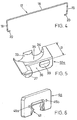
- a linear motion guide is shown, the one has profiled guide rail 1 on which there is a carriage 2 is supported and arranged longitudinally. How 2 can be seen, the carriage 2 is in cross section essentially U-shaped and encompasses with two adjoining a central section Legs 3a, 3b the rail 1. At the front of the car are cover plates 4a, 4b attached to a metallic Base 5 of the car are releasably attached. A The top of the carriage 2 is provided as a mounting surface 9, on which a load to be moved can be attached.
- the carriage is supported by rolling elements 7, each in two are arranged in closed circulations 6a, 6b lateral wings 1a, 1b of the guide rail 1.
- rolling elements 7 each in two are arranged in closed circulations 6a, 6b lateral wings 1a, 1b of the guide rail 1.
- balls as rolling elements intended.
- the wings 1a, 1b of the rail are profiled so that a line contact between the balls and the guide rail is created.
- each of these recesses 10a, 10b is a component from one of the rolling element circulations 6a, 6b, which also each a support zone 11 and two each the ends of the recesses 10a, 10b and the supporting zone connecting deflecting channels exhibit. 2 it can be seen that that a restraint 16 is present in the support zone 11 with which the balls provided as rolling elements 7 guided on the one hand and on the other hand before falling out be prevented from the carriage 2.
- a restraint 16 can a safety bracket shown in Fig.
- the safety bracket 17 be one that runs parallel to the longitudinal axis of movement Retaining web 18 and two ends adjoining Fastening webs 19 has.
- the safety bracket 17 is through the two fastening webs 19 to the End faces 8 of the base body 5 releasably attached, for which end and essentially parallel to the retaining web 18 extending retaining lug 20 of the fastening webs in corresponding Recesses 21a, 21b of the base body 5 engage.
- the safety bracket 17 is preferably made of a resilient Material.
- Fig. 2 and Fig. 3 can be seen that the base body 5 of the carriage in the area of the two ends of each leg 3a, 3b each have a groove 22a, 22b, 22c, 22d.
- the grooves 22a - 22d are each toward the axial recess 12 and lateral outer surfaces 23a, 23b of the carriage open and each have two flat side surfaces 24, 25 and one this orthogonally aligned flat groove base surface 26.
- Insert 32a of mirror-image second type provided by insert designated 32b in Fig. 2 is.
- the inserts 32a, 32b are preferably in one Plastic injection molding process.
- the insert 32a of FIG. 5 has one along an arc of approximately 180 ° inside and one outside Guide surface 33, 34, which is also along a Circular arc of about 180 ° extends. These two guide surfaces 33, 34 are formed by a lower guide surface 35 connected with each other, the transitions from guide surface are steadily trained to guide surface. Up the return channel is limited by one of the groove base surfaces 26 (vg1. Fig. 2). All three guide surfaces 33, 34, 35 extend over the entire return channel. To the Insert 32a are therefore all guide surfaces of the return channel contain.
- the insert 32a also has a surface 36 that is in contact provided on the outer side surface 25 of a groove is, a centering nose 37.
- the centering nose has one Tread of the supporting zone complementary outer surface, so that the latter also due to the generation of the wing Grooves 38a - 38d can be used on each bar is.
- the insert 32a points to the same surface Centering eye 39, which in the respective bore 21a - 21d the web snaps into place.
- the respective bore 21a - 21d and the corresponding centering eye 39 thus form a snap connection, with a width B of the insert and a maximum Measure the height of the centering eye in relation to the surface 36 is that it is only due to elastic deformation can be inserted into the groove 22a-22d.
- the centering eye 39 can be inclined in the insertion direction Have a slope with an inclination angle of, for example, 7 °. After the centering eye a layer directly opposite the hole has reached 21a - 21d, it snaps into this on.
- the distance of the centering eye 39 from the centering nose 37 is slightly smaller than the distance between the bore 21a - 21d from the notch 38a - 38d. This creates in use between the centering eye 39 and the centering nose 37 in essentially a tensile stress opposite the insert 32a the tread and the recess 10a, 10b for the return channels centered and fixed in the respective groove 22a, 22d.
- a cover plate 4a is shown, in each of which Scraper 41 is integrated, for the removal of on the Dirt is in the guide rail.
- the scraper for this purpose has a contour which is essentially the cross-sectional contour corresponds to the rail.
- the cover plate shown can be attached to either end. The returns and the wipers are thus separate separate components.
- FIG. 7 shows that in embodiments according to the invention between the two identical cover plates 4a, 4b and each two of the inserts 32a, 32b on each side of the carriage Snap connections can be provided.
- Each of these Snap connections are primarily used for fastening and exact positioning of the scraper 41.
- the respective Snap connection points on the cover plate 4a, 4b the face of the base body 5 facing a cylindrical projection 44 through which a continuous Lubricant bore 45a, 45b runs (see also Fig. 6), which opens into one of the groove base surfaces 26.
- a slot 46 in the outer surface of the projection in which engages a nose 47 of the insert 32a, 32b, whereby the cover plate is fixed to the base body 5.
Landscapes
- Engineering & Computer Science (AREA)
- General Engineering & Computer Science (AREA)
- Mechanical Engineering (AREA)
- Bearings For Parts Moving Linearly (AREA)
Abstract
Die Erfindung betrifft einen Wagen einer Linearbewegungsführung, welcher zur Anordnung auf einer Schiene vorgesehen ist, der einen Mittelabschnitt und zwei sich jeweils an den Mittelabschnitt anschliessende Schenkel aufweist, wodurch der Wagen im Querschnitt im wesentlichen U-förmig ausgebildet ist und eine zur vorgesehenen Längsbewegungsachse parallel verlaufende Ausnehmung aufweist, der Wagen im Bereich der beiden Schenkel zumindest jeweils einen Wälzkörperumlauf aufweist, wobei jeder Wälzkörperumlauf einen Rücklaufkanal, eine Tragzone sowie zwei den Rücklaufkanal und die Tragzone miteinander verbindende Umlenkkanäle aufweist. Um einen solchen Wagen vor allem einfacher fertigen zu können, wird erfindungsgemäss vorgeschlagen, dass zumindest ein Schenkel (3a, 3b) mit zumindest einer Nut (22a, 22b, 22c, 22d) versehen ist, und dass in die Nut (22a, 22b, 22c, 22d) ein Einsatz (32a, 32b) einfügbar ist, welcher Mittel zur Umlenkung der Wälzkörper (7) enthält. <IMAGE>The invention relates to a carriage of a linear movement guide, which is provided for arrangement on a rail, which has a central section and two legs adjoining the central section, whereby the carriage is essentially U-shaped in cross section and a parallel to the intended longitudinal movement axis Has recess, the carriage in the region of the two legs has at least one rolling element circulation, each rolling element circulation having a return channel, a support zone and two deflection channels connecting the return channel and the support zone. In order to be able to manufacture such a carriage more easily, it is proposed according to the invention that at least one leg (3a, 3b) is provided with at least one groove (22a, 22b, 22c, 22d) and that the groove (22a, 22b, 22c, 22d) an insert (32a, 32b) can be inserted, which contains means for deflecting the rolling elements (7). <IMAGE>
Description
Die Erfindung betrifft einen Wagen einer Linearbewegungsführung, welcher zur Anordnung auf einer Schiene vorgesehen ist, der einen Mittelabschnitt und zwei sich jeweils an den Mittelabschnitt anschliessende Schenkel aufweist, wodurch der Wagen im Querschnitt im wesentlichen U-förmig ausgebildet ist und eine zur vorgesehenen Längsbewegungsachse parallel verlaufende Ausnehmung aufweist. Der Wagen weist im Bereich der beiden Schenkel zumindest jeweils einen Wälzkörperumlauf auf, wobei jeder Wälzkörperumlauf mit einem Rücklaufkanal, einen Tragbereich sowie zwei den Rücklaufkanal und den Tragbereich miteinander verbindende Umlenkkanäle versehen ist.The invention relates to a carriage of a linear motion guide, which is intended for arrangement on a rail is a middle section and two each on the Middle section adjoining legs, whereby the carriage is essentially U-shaped in cross section and is parallel to the intended longitudinal movement axis has extending recess. The car points in the area of the two legs at least one rolling element circulation each rolling element circulation with a return channel, a support area and two the return channel and deflecting channels connecting the supporting area to one another is provided.
Wälzlagerlinearführungen werden in vielen Bereichen der Technik eingesetzt, in denen ein Bauteil gegenüber einem anderen Bauteil geradlinig und möglichst ohne Reibungsverluste bewegt werden soll. Ein Beispiel hierfür sind Werkzeugmaschinen. Derartige Führungen weisen einen Wagen oder Schlitten auf, der über Wälzkörper, wie Kugeln, Rollen oder Nadeln, an einer Schiene geführt ist. Die Wälzkörper zirkulieren hierbei in in sich geschlossenen Wälzkörperumläufen des Wagens. Sie weisen üblicherweise eine Tragzone auf, in welcher die Wälzkörper an einer Tragfläche des Wagens und an der Schiene anliegen und hierdurch die zu bewegende Last tragen. Durch die Linearbewegung des Wagens gelangen die Wälzkörper aus der Tragzone in einen ersten Umlenkkanal, in dem die Wälzkörper von der Tragzone in den Rücklaufkanal überführt werden. Nach Durchlaufen des Rücklaufkanals erreichen die Wälzkörper über einen zweiten Umlenkkanal wieder die Tragzone. Roller bearing linear guides are used in many areas of the Technology used in which one component versus another Component straight and without any loss of friction if possible should be moved. Machine tools are an example of this. Such guides have a carriage or carriage on the rolling elements, such as balls, rollers or needles, is guided on a rail. The rolling elements circulate here in self-contained rolling element revolutions of the Car. They usually have a supporting zone in which the rolling elements on a wing of the car and on the rail and thereby the load to be moved wear. Due to the linear movement of the carriage, the Rolling elements from the bearing zone into a first deflection channel, in which the rolling elements from the support zone in the return channel be transferred. Reach after passing through the return duct the rolling elements again via a second deflection channel the bearing zone.
In vielen Fällen werden die Umlenkkanäle von einer jeweils stirnseitig an einen Grundkörper des Wagens angesetzte und dort befestigte Bauteilgruppe gebildet, die zumindest teilweise die erforderliche Führungsmittel zur Umlenkung enthalten. In der Regel enthält diese Bauteilgruppe Führungsmittel von sämtlichen an der jeweiligen Stirnseite angeordneten Umlenkungen. Ausserdem kann in die Bauteilgruppe auch ein Abstreifer integriert sein, mit dem das Eindringen von Schmutz in den Wagen verhindert werden soll.In many cases, the deflection channels are each one attached to the front of a body of the car and attached component group formed there, at least partially contain the necessary guide means for redirection. As a rule, this component group contains guide means of all deflections arranged on the respective end face. A wiper can also be used in the component group be integrated with which the penetration of dirt to be prevented in the car.
Es sind bereits einige miniaturisierte Linearbewegungsführungen bekannt geworden, die häufig im Halbleitermaschinenbereich eingesetzt werden. Bei diesen Linearbewegungsführungen ist in der Regel an jedem Schenkel des Wagens nur ein Wälzkörperumlauf vorhanden, da sich bereits hiermit die auftretenden Lasten abtragen lassen. Ansonsten wird die Miniaturisierung dieser Linearbewegungsführungen dadurch erreicht, dass man die weitverbreiteten grösseren Linearbewegungsführungen - sonst im wesentlichen konstruktiv - unverändert in einem kleineren Massstab realisiert. Dies hat jedoch den Nachteil, dass die Wagen konstruktiv verhältnismässig aufwendig aufgebaut sind, da relativ viele Bauteile benötigt werden. Da sich die Fertigungstoleranzen der einzelnen Bauteile aufaddieren, müssen an die einzelnen Bauteile vergleichsweise hohe Anforderungen an die Fertigungsgenauigkeit gestellt werden. Aufgrund der geringen Grösse der Wagen wären die Genauigkeitsanforderungen an sich jedoch einfacher einzuhalten, als bei grösseren Linearbewegungsführungen.There are already some miniaturized linear motion guides become known, often in the semiconductor machine sector be used. With these linear motion guides is usually only one on each leg of the car Rolling element circulation available, since this already occurs Have loads carried away. Otherwise miniaturization of these linear motion guides that the widespread larger linear motion guides - otherwise essentially constructive - unchanged realized on a smaller scale. However, this has the disadvantage that the cars are structurally proportionate are complex, since a relatively large number of components are required become. Because the manufacturing tolerances of each Adding up components must go to the individual components comparatively high demands on manufacturing accuracy be put. Because of the small size of the car the accuracy requirements per se would be simpler to be observed than with larger linear motion guides.
Bei vielen der vorbekannten Linearbewegungsführungen kann auch nicht überzeugen, dass für unterschiedliche Breiten von Wagen jeweils ein gesondertes stirnseitiges Bauteil für die Rückführungen konstruiert, gefertigt und eventuell bevorratet werden muss. Dies ist jedoch erforderlich, da die stirnseitigen Bauteile, welche Führungsmittel für Umlenkungen enthalten, jeweils auf eine bestimmte Wagenbreite abgestimmt sind.Many of the known linear motion guides can also not convince that for different widths of Wagons each have a separate front-end component for the Returns designed, manufactured and possibly stocked must become. However, this is necessary because the front Components which guide means for deflections included, each tuned to a specific carriage width are.
Der Erfindung liegt deshalb die Aufgabe zugrunde, einen Wagen einer Linearbewegungsführung, insbesondere für kleine Linearbewegungsführungen, zu schaffen, der konstruktiv einfach aufgebaut ist und der sich mit wenigen Fertigungsschritten realisieren lässt.The invention is therefore based on the object of a carriage a linear motion control, especially for small ones Linear motion guides, to create the structurally simple is set up and can be completed in just a few steps can be realized.
Diese Aufgabe wird bei einem eingangs erwähnten Wagen erfindungsgemäss dadurch gelöst, dass zumindest ein Schenkel eine Nut aufweist, und dass in die Nut ein Einsatz einfügbar ist, welcher Mittel zur Umlenkung der Wälzkörper enthält. Die Erfindung lässt sich jedoch nicht nur bei einen Wagen einer Linearbewegungsführung einsetzen. Sie kann bei nahezu jeder Führung verwendet werden, bei der Wälzkörper in einem Wälzkörperumlauf mit einem Tragbereich, einem Rücklaufkanal sowie zwei den Tragbereich und den Rücklaufkanal miteinander verbindende Umlenkkanäle zirkulieren.This object is achieved according to the invention in a carriage mentioned at the beginning solved that at least one leg Has groove, and that an insert can be inserted into the groove, which contains means for deflecting the rolling elements. The invention However, you can not only have one car Insert linear motion guide. It can be used by almost everyone Guide are used in the rolling elements in a rolling element circulation with a support area, a return channel and two the support area and the return channel with each other circulating connecting deflection channels.
Ein Vorteil der erfindungsgemässen Lösung besteht insbesondere darin, dass sie die Möglichkeit bietet, mit ein und denselben Umlenkkorpern Wagen von beliebiger Breite und Länge bilden zu können. Es ist somit möglich, mit weniger unterschiedlichen Bauteilen als bisher Wagen mit unterschiedlicher Grösse zu bilden. Diese Reduzierung der hierfür erforderlichen Bauteile senkt den Fertigungsaufwand ganz erheblich.One advantage of the solution according to the invention is in particular in that it offers the possibility of using one and the same deflection carts of any width and length to be able to educate. It is therefore possible to use less different Components than previously with different wagons To form greatness. This reduction in the necessary Components significantly reduce manufacturing costs.
Der Grundkörper eines erfindungsgemässen Wagens lässt sich besonders einfach und kostengünstig herstellen, wenn die zumindest eine Nut im wesentlichen quer zur Ausnehmung verläuft, wobei die Nut von zwei im wesentlichen orthogonal zur Längsbewegungsachse ausgerichtete Seitenflächen des Grundkörpers begrenzt wird. Eine derartige Nut kann nämlich mit einem herkömmlichen Fräswerkzeug erzeugt werden. The basic body of a carriage according to the invention can be particularly easy and inexpensive to manufacture, if at least a groove runs essentially transversely to the recess, the groove of two being substantially orthogonal to Lateral surfaces of the base body aligned in the longitudinal movement axis is limited. Such a groove can namely with a conventional milling tool.
Zur Reduzierung der erforderlichen Bauteile trägt auch dazu bei, wenn die für einen Wälzkörperumlauf vorgesehenen erfindungsgemässen Umlenkkörper einteilig ausgebildet sind. Es hat sich als günstig erwiesen, wenn die Umlenkkörper in einem Kunststoffspritzgiessverfahren hergestellt werden. Ausser aus Kunststoff könnten diese jedoch auch aus Stahl oder anderen Metallen bestehen, was insbesondere für Anwendungen im Vakuumbereich zweckmässig sein kann.Reducing the required components also helps at when the provided for a rolling element circulation according to the invention Deflection bodies are formed in one piece. It has proven to be favorable if the deflecting body in one Plastic injection molding processes are manufactured. Except made of plastic, but could also be made of steel or other metals exist, which is especially for applications can be useful in the vacuum range.
Ein weiterer Vorteil der Erfindung kann darin gesehen werden, dass sich die im Umlenkbereich von den Wälzkörpern auf einen Umlenkkörper wirkenden Kräfte besonders gut in den Wagen ableiten lassen. Diese Kräfte wirken nämlich vor allem parallel zur Längsbewegungsachse. Da die erfindungsgemäss im Grundkörper des Wagens vorgesehene Nut von vertikal zur Längsbewegungsachse ausgerichteten Seitenwänden des Grundkörpers begrenzt wird, können die Kräfte über die Seitenwände abgeleitet werden. Erfindungsgemässe Wagen können deshalb besonders robust sein.Another advantage of the invention can be seen in that in the deflection area from the rolling elements forces acting particularly well in the carriage derive. These forces work above all parallel to the longitudinal axis of movement. Since the invention in Basic body of the carriage provided groove from vertical to Side walls of the base body aligned with the longitudinal movement axis the forces can be limited via the side walls be derived. Cars according to the invention can therefore be particularly robust.
Um den Fertigungs- und Montageaufwand weiter zu reduzieren, kann es zweckmässig sein, wenn die Umlenkkörper als in die jeweilige Nut einzufügende Einsätze ausgebildet sind, die am Grundkörper lediglich durch eine Schnappverbindung befestigbar sind.In order to further reduce manufacturing and assembly costs, it may be appropriate if the deflection as in the respective groove inserts are formed, which on Base body can only be attached by a snap connection are.
Es hat sich ferner als vorteilhaft erwiesen, wenn der Einsatz mit Zentriermitteln versehen ist, mit denen der Umlenkkanal zu der Tragzone und dem Rücklaufkanal in vorbestimmter Weise ausgerichtet werden kann.It has also proven to be advantageous if the use is provided with centering means with which the deflection channel to the support zone and the return channel in a predetermined Way can be aligned.
Ein weiterer Vorteil kann dadurch erzielt werden, dass die Abstreifer von den Umlenkkörpern getrennte Bauteile sind. Dadurch ist es möglich die verschleissanfälligen Abstreifer auszutauschen, ohne die Umlenkörper wechseln zu müssen. Another advantage can be achieved that the Wipers are separate components from the deflectors. This makes it possible to use wipers that are prone to wear replace without having to change the deflection.
Weitere bevorzugte Ausgestaltungen der Erfindung ergeben sich aus den abhängigen Ansprüchen.Further preferred configurations of the invention result themselves from the dependent claims.
Die Erfindung wird anhand den in den Figuren schematisch dargestellten Ausführungsbeispielen näher erläutert; es zeigen:
- Fig. 1
- eine perspektivische Darstellung einer erfindungsgemässen Linearbewegungsführung;
- Fig. 2
- ein teilweise montierter Wagen der Linearbewegungsführung aus Fig. 1 in einer Teilansicht;
- Fig. 3
- ein Grundkörper des Wagens von Fig. 1 in einer perspektivischen Darstellung;
- Fig. 4
- ein Sicherungsbügel des Wagens von Fig.1;
- Fig. 5
- ein Umlenkkörper in einer perspektivischen Darstellung;
- Fig. 6
- eine Deckplatte mit einem Abstreifer in einer perspektivischen Darstellung.
- Fig. 7
- ein Teil einer Längsschnittdarstellung eines erfindungsgemässen Wagens.
- Fig. 1
- a perspective view of a linear motion guide according to the invention;
- Fig. 2
- a partially assembled carriage of the linear motion guide of Figure 1 in a partial view.
- Fig. 3
- a basic body of the carriage of Figure 1 in a perspective view.
- Fig. 4
- a safety bracket of the carriage of Fig.1;
- Fig. 5
- a deflecting body in a perspective view;
- Fig. 6
- a cover plate with a wiper in a perspective view.
- Fig. 7
- part of a longitudinal sectional view of a carriage according to the invention.
In Fig. 1 ist eine Linearbewegungsführung gezeigt, die eine
profilierte Führungsschiene 1 aufweist, auf der sich ein Wagen
2 abstützt und längsverschiebbar angeordnet ist. Wie
auch Fig. 2 entnommen werden kann, ist der Wagen 2 im Querschnitt
im wesentlichen U-förmig ausgebildet und umgreift
mit zwei sich an einen Mittelabschnitt anschliessenden
Schenkeln 3a, 3b die Schiene 1. An den Stirnseiten des Wagens
sind Deckplatten 4a, 4b angebracht, die an einem metallischen
Grundkörper 5 des Wagens lösbar befestigt sind. Eine
Oberseite des Wagens 2 ist als Montagefläche 9 vorgesehen,
auf der eine zu bewegende Last befestigt werden kann.In Fig. 1, a linear motion guide is shown, the one
has profiled guide rail 1 on which there is a
Der Wagen stützt sich über Wälzkörper 7, die in zwei jeweils
in sich geschlossenen Umläufen 6a, 6b angeordnet sind, auf
seitlichen Tragflächen 1a, 1b der Führungsschiene 1 ab. Im
dargestellten Ausführungsbeispiel sind als Wälzkörper 7 Kugeln
vorgesehen. Die Tragflächen 1a, 1b der Schiene sind
profiliert, so dass eine Linienberührung zwischen den Kugeln
und der Führungsschiene entsteht.The carriage is supported by rolling
Im metallischen Grundkörper 5 sind zwei zylindrische Ausnehmungen
10a, 10b (vgl. Fig. 3) eingebracht, deren jeweilige
Längsachse parallel zur Längsbewegungsachse der Schiene 1
verläuft. Jede dieser Ausnehmungen 10a, 10b ist Bestandteil
von einem der Wälzkörperumläufe 6a, 6b, die zudem jeweils
eine Tragzone 11 und zwei jeweils die Enden der Ausnehmungen
10a, 10b und der Tragzone miteinander verbindende Umlenkkanäle
aufweisen. In der Darstellung von Fig. 2 ist zu erkennen,
dass in der Tragzone 11 ein Rückhaltemittel 16 vorhanden
ist, mit dem die als Wälzkörper 7 vorgesehenen Kugeln
einerseits geführt und andererseits vor einem Herausfallen
aus dem Wagen 2 gehindert werden. Ein solches Rückhaltemittel
16 kann ein in Fig. 4 näher dargestellter Sicherungsbügel
17 sein, der einen parallel zur Längsbewegungsachse verlaufenden
Rückhaltesteg 18 sowie zwei sich an die Enden anschliessende
Befestigungsstege 19 aufweist. Der Sicherungsbügel
17 ist durch die beiden Befestigungsstege 19 an den
Stirnseiten 8 des Grundkörpers 5 lösbar befestigt, wozu endseitige
und im wesentlichen parallel zum Rückhaltesteg 18
verlaufende Haltenase 20 der Befestigungsstege in entsprechende
Ausnehmungen 21a, 21b des Grundkörpers 5 eingreifen.
Der Sicherungsbügel 17 besteht vorzugsweise aus einem federelastischen
Material. In the metallic base body 5 are two
Fig. 2 und Fig. 3 kann entnommen werden, dass der Grundkörper
5 des Wagens im Bereich der beiden Enden jedes Schenkels
3a, 3b jeweils eine Nut 22a, 22b, 22c, 22d aufweist. Die Nuten
22a - 22d sind jeweils zur axialen Ausnehmung 12 und zu
seitlichen Aussenflächen 23a, 23b des Wagens hin offen und
weisen jeweils zwei ebene Seitenflächen 24, 25 und eine zu
diesen orthogonal ausgerichtete ebene Nutgrundfläche 26 auf.Fig. 2 and Fig. 3 can be seen that the base body
5 of the carriage in the area of the two ends of each
Weil die ebenen Seitenflächen 24, 25, welche die Nuten 22a -
22d jeweils begrenzen, orthogonal zur Längsbewegungsachse
ausgerichtet sind, ergibt sich, dass die Nuten 22a - 22d
auch jeweils orthogonal zur Ausnehmung 12 verlaufen. Zwischen
der jeweils äusseren Seitenfläche 25 jeder Nut 22a -
22d und den Stirnflächen 8 des Grundkörpers befindet sich
somit jeweils nur ein Steg 27a - 27d von vergleichsweise geringer
Breite. Da die Bohrungen für die Ausnehmungen 10a,
10b der beiden Rücklaufkanäle eingebracht werden, bevor die
Nuten 22a - 22d gefräst werden, ist auch in jedem Steg 27a-27d
eine durchgehende Ausnehmung 21a- 21d vorhanden, deren
Längsachse mit der Längsachse des jeweiligen Rücklaufkanals
fluchtet. Nachdem auch vor der Erzeugung der vier Nuten 22a
- 22d an den Innenseiten der Schenkel 3a, 3b über deren gesamte
Länge die im Querschnitt kreisbogenförmigen Laufflächen
der Tragzone bearbeitet werden, weisen auch die Stege
27a- 27b jeweils an ihren Innenseiten eine der Tragflächen
entsprechende Kontur auf. Schliesslich ist an jedem Steg 27a
- 27b eine weitere Ausnehmung 31a -31d vorhanden, deren
Funktion nachfolgend noch erläutert wird.Because the flat side surfaces 24, 25, which the
In Fig. 5 ist nun ein als einstückiger Einsatz 32a ausgebildeter
Umlenkkörper gezeigt, der in zwei sich diagonal gegenüberliegenden
Nuten 22a, 22d des Grundkörpers einsetzbar
ist. In die beiden anderen Nuten 22b, 22c ist ein zum dargestellten
Einsatz 32a spiegelbildlich aufgebauter zweiter Typ
von Einsatz vorgesehen, der in Fig. 2 mit 32b bezeichnet
ist. Die Einsätze 32a, 32b werden vorzugsweise in einem
Kunststoffspritzgiessverfahren hergestellt.5 is a one-
Der Einsatz 32a von Fig. 5 weist eine entlang eines Kreisbogens
von in etwa 180° verlaufende innere sowie eine äussere
Führungsfläche 33, 34 auf, die sich ebenfalls entlang eines
Kreisbogens von etwa 180° erstreckt. Diese beiden Führungsflächen
33, 34 werden durch eine untere Führungsfläche 35
miteinander verbunden, wobei die Übergänge von Führungsfläche
zu Führungsfläche stetig ausgebildet sind. Nach oben
wird der Rücklaufkanal durch eine der Nutgrundflächen 26 begrenzt
(vg1. Fig. 2). Sämtliche drei Führungsflächen 33, 34,
35 erstrecken sich über den gesamten Rücklaufkanal. An dem
Einsatz 32a sind somit sämtliche Führungsflächen des Rücklaufkanals
enthalten.The
Der Einsatz 32a weist ferner an einer Fläche 36, die zur Anlage
an der äusseren Seitenfläche 25 einer Nut vorgesehen
ist, eine Zentriernase 37 auf. Die Zentriernase hat eine zur
Lauffläche der Tragzone komplementäre Aussenfläche, so dass
letztere in die aufgrund der Erzeugung der Tragfläche auch
an jedem Steg vorhandene Einkerbung 38a - 38d einsetzbar
ist. An einer Stirnseite der Zentriernase ist ein Schlitz
eingebracht, der zur Aufnahme eines Befestigungssteges 19
des Sicherungsbügels 17 vorgesehen ist.The
Ausserdem weist der Einsatz 32a an der gleichen Fläche ein
Zentrierauge 39 auf, das in die jeweilige Bohrung 21a - 21d
des Steges einschnappt. Die jeweilige Bohrung 21a - 21d und
das entsprechende Zentrierauge 39 bilden somit eine Schnappverbindung,
wobei eine Breite B des Einsatzes und eine maximale
Höhe des Zentrierauges gegenüber der Fläche 36 so bemessen
ist, dass es nur aufgrund einer elastischen Verformung
in die Nut 22a - 22d einfügbar ist. Um das Einfügen des
Einsatzes 32a in die jeweilige Nut 22a, 22d zu erleichtern,
kann das Zentrierauge 39 eine in Einfügrichtung geneigte
Schräge mit einem Neigungswinkel von beispielsweise 7° aufweisen.
Nachdem das Zentrierauge eine Lage direkt gegenüber
der Bohrung 21a - 21d erreicht hat, schnappt es in diese
ein. Der Abstand des Zentrierauges 39 von der Zentriernase
37 ist geringfügig kleiner als der Abstand der Bohrung 21a -
21d von der Einkerbung 38a - 38d. Dadurch entsteht im Einsatz
zwischen dem Zentrierauge 39 und der Zentriernase 37 im
wesentlichen eine Zugspannung, die den Einsatz 32a gegenüber
der Lauffläche und der Ausnehmung 10a, 10b für die Rücklaufkanäle
zentriert und in der jeweiligen Nut 22a, 22d fixiert.In addition, the
In Fig. 6 ist eine Deckplatte 4a gezeigt, in die jeweils ein
Abstreifer 41 integriert ist, der zur Entfernung von auf der
Führungsschiene befindlichem Schmutz dient. Der Abstreifer
weist dazu eine Kontur auf, die im wesentlichen der Querschnittskontur
der Schiene entspricht. Die gezeigte Deckplatte
kann an jeder der beiden Stirnseiten befestigt werden.
Die Rückführungen und die Abstreifer sind somit voneinander
getrennte Bauteile.In Fig. 6, a
Fig. 7 zeigt, dass bei efindungsgemässen Ausführungsformen
zwischen den beiden baugleichen Deckplatte 4a, 4b und jedem
der beiden Einsätze 32a, 32b auf jeder Seite des Wagens zwei
Schnappverbindungen vorgesehen sein können. Jeder dieser
Schnappverbindungen dienen in erster Linie zur Befestigung
und exakten Positionierung des Abstreifers 41. Die jeweilige
Schnappverbindung weist an der Deckplatte 4a, 4b an einer
der Stirnseite des Grundkörpers 5 zugewandten Fläche einen
zylindrischen Vorsprung 44 auf, durch den eine durchgehende
Schmiermittelbohrung 45a, 45b verläuft (vgl. auch Fig.6),
die jeweils in eine der Nutgrundflächen 26 mündet. An einer
Aussenfläche des Vorsprungs ist ein Schlitz 46 vorhanden, in
den eine Nase 47 des Einsatzes 32a, 32b eingreift, wodurch
die Deckplatte am Grundkörper 5 fixiert wird.7 shows that in embodiments according to the invention
between the two
Claims (15)
Applications Claiming Priority (2)
| Application Number | Priority Date | Filing Date | Title |
|---|---|---|---|
| CH175498 | 1998-08-27 | ||
| CH175498 | 1998-08-27 |
Publications (2)
| Publication Number | Publication Date |
|---|---|
| EP0982509A1 true EP0982509A1 (en) | 2000-03-01 |
| EP0982509B1 EP0982509B1 (en) | 2004-10-20 |
Family
ID=4217791
Family Applications (1)
| Application Number | Title | Priority Date | Filing Date |
|---|---|---|---|
| EP99115859A Expired - Lifetime EP0982509B1 (en) | 1998-08-27 | 1999-08-12 | Linear motion guide |
Country Status (4)
| Country | Link |
|---|---|
| US (1) | US6210040B1 (en) |
| EP (1) | EP0982509B1 (en) |
| JP (1) | JP4356045B2 (en) |
| DE (1) | DE59910887D1 (en) |
Cited By (1)
| Publication number | Priority date | Publication date | Assignee | Title |
|---|---|---|---|---|
| EP1245845A1 (en) * | 2001-03-29 | 2002-10-02 | Nippon Thompson Co., Ltd. | Linear motion guide unit |
Families Citing this family (12)
| Publication number | Priority date | Publication date | Assignee | Title |
|---|---|---|---|---|
| TW429290B (en) * | 2000-05-24 | 2001-04-11 | Hiwin Tech Corp | A linear guide way |
| JP4864722B2 (en) * | 2004-11-15 | 2012-02-01 | Thk株式会社 | Motion guide device, table device, and damping method of motion guide device |
| US7377693B2 (en) * | 2006-02-24 | 2008-05-27 | Hiwin Technologies Corp. | Steel wire retainer for a sliding block |
| US7467894B2 (en) * | 2006-05-15 | 2008-12-23 | Hiwin Technologies Corp. | Linear motion guide apparatus having ball retaining device |
| JP2010078108A (en) * | 2008-09-29 | 2010-04-08 | Thk Co Ltd | Movement guiding device |
| BR112013033506B1 (en) * | 2011-06-30 | 2021-01-12 | Smc Kabushiki Kaisha | linear actuator |
| TWM434859U (en) * | 2011-11-25 | 2012-08-01 | Kuo-Le Tsao | Linear slider structure improvement |
| JP6201344B2 (en) * | 2012-03-27 | 2017-09-27 | Thk株式会社 | Exercise equipment |
| EP2980428A4 (en) * | 2013-03-27 | 2016-11-02 | Nsk Ltd | Oil supply device for linear guide device, and linear guide device |
| RU2651354C2 (en) * | 2014-02-03 | 2018-04-19 | СМСи КОРПОРЕЙШН | Linear actuator |
| TWI587975B (en) * | 2014-02-05 | 2017-06-21 | Smc股份有限公司 | Linear actuator |
| WO2017214946A1 (en) * | 2016-06-16 | 2017-12-21 | 深圳市创客工场科技有限公司 | Connecting rod and connecting assembly |
Citations (8)
| Publication number | Priority date | Publication date | Assignee | Title |
|---|---|---|---|---|
| EP0124648A2 (en) * | 1983-04-12 | 1984-11-14 | Ipiranga Sa | Linear bearing arrangement for the rectilinear guiding of a carriage along a guiding rail |
| DE3604283A1 (en) * | 1985-02-15 | 1986-08-21 | Nippon Thompson Co Ltd | Linear roller bearing with a continuous roller recirculation track |
| US4798479A (en) * | 1987-04-14 | 1989-01-17 | Nippon Thompson Co., Ltd. | Sheet-metal type endless rectilinear motion rolling guide unit |
| DE3931351A1 (en) * | 1989-09-20 | 1991-03-28 | Werner Dipl Ing Jacob | Linear ball bearing with several continuous rows of balls - incorporates rail, cage, guide grooves and base members |
| US5492413A (en) * | 1993-07-22 | 1996-02-20 | Nsk Ltd. | Sealing device for a linear guide |
| US5544954A (en) * | 1994-09-22 | 1996-08-13 | Nsk Ltd. | Ball retainers in a linear guide apparatus |
| EP0802337A2 (en) * | 1996-04-20 | 1997-10-22 | INA Wälzlager Schaeffler KG | Linear rolling bearing |
| EP0845611A1 (en) * | 1996-06-18 | 1998-06-03 | Thk Co. Ltd. | Linear motion guide apparatus equipped with a plurality of rows of ball chains |
Family Cites Families (3)
| Publication number | Priority date | Publication date | Assignee | Title |
|---|---|---|---|---|
| US4502737A (en) * | 1981-11-18 | 1985-03-05 | Nippon Seiko Kabushiki Kaisha | Slide way bearing |
| JPS60151417A (en) * | 1984-01-17 | 1985-08-09 | Nippon Thompson Co Ltd | Endless circulating passage of roller bearing for rectilinear motion |
| US5106206A (en) * | 1991-01-30 | 1992-04-21 | Nippon Thompson Co., Ltd. | Linear motion guide unit manufactured from a resin |
-
1999
- 1999-08-12 EP EP99115859A patent/EP0982509B1/en not_active Expired - Lifetime
- 1999-08-12 DE DE59910887T patent/DE59910887D1/en not_active Expired - Lifetime
- 1999-08-25 JP JP27727799A patent/JP4356045B2/en not_active Expired - Fee Related
- 1999-08-27 US US09/384,087 patent/US6210040B1/en not_active Expired - Lifetime
Patent Citations (8)
| Publication number | Priority date | Publication date | Assignee | Title |
|---|---|---|---|---|
| EP0124648A2 (en) * | 1983-04-12 | 1984-11-14 | Ipiranga Sa | Linear bearing arrangement for the rectilinear guiding of a carriage along a guiding rail |
| DE3604283A1 (en) * | 1985-02-15 | 1986-08-21 | Nippon Thompson Co Ltd | Linear roller bearing with a continuous roller recirculation track |
| US4798479A (en) * | 1987-04-14 | 1989-01-17 | Nippon Thompson Co., Ltd. | Sheet-metal type endless rectilinear motion rolling guide unit |
| DE3931351A1 (en) * | 1989-09-20 | 1991-03-28 | Werner Dipl Ing Jacob | Linear ball bearing with several continuous rows of balls - incorporates rail, cage, guide grooves and base members |
| US5492413A (en) * | 1993-07-22 | 1996-02-20 | Nsk Ltd. | Sealing device for a linear guide |
| US5544954A (en) * | 1994-09-22 | 1996-08-13 | Nsk Ltd. | Ball retainers in a linear guide apparatus |
| EP0802337A2 (en) * | 1996-04-20 | 1997-10-22 | INA Wälzlager Schaeffler KG | Linear rolling bearing |
| EP0845611A1 (en) * | 1996-06-18 | 1998-06-03 | Thk Co. Ltd. | Linear motion guide apparatus equipped with a plurality of rows of ball chains |
Cited By (2)
| Publication number | Priority date | Publication date | Assignee | Title |
|---|---|---|---|---|
| EP1245845A1 (en) * | 2001-03-29 | 2002-10-02 | Nippon Thompson Co., Ltd. | Linear motion guide unit |
| US6520681B2 (en) | 2001-03-29 | 2003-02-18 | Nippon Thompson Co., Ltd. | Linear motion guide unit |
Also Published As
| Publication number | Publication date |
|---|---|
| JP2000120677A (en) | 2000-04-25 |
| JP4356045B2 (en) | 2009-11-04 |
| US6210040B1 (en) | 2001-04-03 |
| EP0982509B1 (en) | 2004-10-20 |
| DE59910887D1 (en) | 2004-11-25 |
Similar Documents
| Publication | Publication Date | Title |
|---|---|---|
| DE3627169C2 (en) | Linear rolling element guidance | |
| EP2217820B1 (en) | Cage for a rolling element bearing and method for the production thereof | |
| EP0982509B1 (en) | Linear motion guide | |
| DE4032820C1 (en) | ||
| EP0472167A2 (en) | Rolling contact bearing for linear movement, say rail guided rollers | |
| DE3416207A1 (en) | LINEAR BALL BEARING ARRANGEMENT | |
| DE3688289T2 (en) | MOVABLE TABLE. | |
| EP1236912B1 (en) | Linear motion guide with guided cage for rolling elements | |
| DE102005004659B4 (en) | Longitudinal guide for vehicle seats | |
| DE112012003767B4 (en) | Motion control device | |
| DE3333795A1 (en) | ROLLED BEARING LONGITUDINAL GUIDE WITH SLIDE | |
| DE9011444U1 (en) | Rolling bearings for linear movements | |
| WO2000008344A1 (en) | Carriage for linear guiding device | |
| DE3905566C1 (en) | Constant velocity joint with axially movable joint parts | |
| EP0601028B1 (en) | Rolling bearing for linear movements | |
| DE4133310A1 (en) | ROLLER BEARING GUIDE UNIT WITH FOUR ENDLESS ROLLER BEARING ELEMENTS | |
| DE102007013516B4 (en) | linear bearings | |
| EP1612436B1 (en) | Linear bearing with profiled rail | |
| DE9011413U1 (en) | linear actuator | |
| DE9301112U1 (en) | Profile body with polygon core | |
| DE102016012025B3 (en) | Toggle-clamping unit of a plastic processing machine, in particular an injection molding machine | |
| DE4227599C2 (en) | Longitudinal guide with a rolling element bearing | |
| DE3317121C2 (en) | ||
| EP0040394B1 (en) | Arrangement for a rectilinear guide of a machine element along a girder | |
| EP1308641A1 (en) | Guiding cart for profiled guiding rails |
Legal Events
| Date | Code | Title | Description |
|---|---|---|---|
| PUAI | Public reference made under article 153(3) epc to a published international application that has entered the european phase |
Free format text: ORIGINAL CODE: 0009012 |
|
| AK | Designated contracting states |
Kind code of ref document: A1 Designated state(s): CH DE FR GB IT LI NL |
|
| AX | Request for extension of the european patent |
Free format text: AL;LT;LV;MK;RO;SI |
|
| 17P | Request for examination filed |
Effective date: 20000525 |
|
| AKX | Designation fees paid |
Free format text: CH DE FR GB IT LI NL |
|
| RBV | Designated contracting states (corrected) |
Designated state(s): CH DE FR GB IT LI NL |
|
| 17Q | First examination report despatched |
Effective date: 20031010 |
|
| GRAP | Despatch of communication of intention to grant a patent |
Free format text: ORIGINAL CODE: EPIDOSNIGR1 |
|
| GRAS | Grant fee paid |
Free format text: ORIGINAL CODE: EPIDOSNIGR3 |
|
| GRAA | (expected) grant |
Free format text: ORIGINAL CODE: 0009210 |
|
| AK | Designated contracting states |
Kind code of ref document: B1 Designated state(s): CH DE FR GB IT LI NL |
|
| REG | Reference to a national code |
Ref country code: GB Ref legal event code: FG4D Free format text: NOT ENGLISH |
|
| REG | Reference to a national code |
Ref country code: CH Ref legal event code: EP |
|
| REF | Corresponds to: |
Ref document number: 59910887 Country of ref document: DE Date of ref document: 20041125 Kind code of ref document: P |
|
| REG | Reference to a national code |
Ref country code: CH Ref legal event code: NV Representative=s name: R. A. EGLI & CO. PATENTANWAELTE |
|
| GBT | Gb: translation of ep patent filed (gb section 77(6)(a)/1977) |
Effective date: 20050116 |
|
| PLBE | No opposition filed within time limit |
Free format text: ORIGINAL CODE: 0009261 |
|
| STAA | Information on the status of an ep patent application or granted ep patent |
Free format text: STATUS: NO OPPOSITION FILED WITHIN TIME LIMIT |
|
| ET | Fr: translation filed | ||
| 26N | No opposition filed |
Effective date: 20050721 |
|
| PGFP | Annual fee paid to national office [announced via postgrant information from national office to epo] |
Ref country code: FR Payment date: 20070812 Year of fee payment: 9 |
|
| REG | Reference to a national code |
Ref country code: FR Ref legal event code: ST Effective date: 20090430 |
|
| PG25 | Lapsed in a contracting state [announced via postgrant information from national office to epo] |
Ref country code: FR Free format text: LAPSE BECAUSE OF NON-PAYMENT OF DUE FEES Effective date: 20080901 |
|
| PGFP | Annual fee paid to national office [announced via postgrant information from national office to epo] |
Ref country code: GB Payment date: 20100819 Year of fee payment: 12 |
|
| GBPC | Gb: european patent ceased through non-payment of renewal fee |
Effective date: 20110812 |
|
| PG25 | Lapsed in a contracting state [announced via postgrant information from national office to epo] |
Ref country code: GB Free format text: LAPSE BECAUSE OF NON-PAYMENT OF DUE FEES Effective date: 20110812 |
|
| PGFP | Annual fee paid to national office [announced via postgrant information from national office to epo] |
Ref country code: DE Payment date: 20180823 Year of fee payment: 20 Ref country code: NL Payment date: 20180821 Year of fee payment: 20 Ref country code: IT Payment date: 20180830 Year of fee payment: 20 |
|
| PGFP | Annual fee paid to national office [announced via postgrant information from national office to epo] |
Ref country code: CH Payment date: 20181128 Year of fee payment: 20 |
|
| REG | Reference to a national code |
Ref country code: DE Ref legal event code: R071 Ref document number: 59910887 Country of ref document: DE |
|
| REG | Reference to a national code |
Ref country code: NL Ref legal event code: MK Effective date: 20190811 |
|
| REG | Reference to a national code |
Ref country code: CH Ref legal event code: PL |