EP0801454B1 - Kabelmuffe - Google Patents
Kabelmuffe Download PDFInfo
- Publication number
- EP0801454B1 EP0801454B1 EP96200916A EP96200916A EP0801454B1 EP 0801454 B1 EP0801454 B1 EP 0801454B1 EP 96200916 A EP96200916 A EP 96200916A EP 96200916 A EP96200916 A EP 96200916A EP 0801454 B1 EP0801454 B1 EP 0801454B1
- Authority
- EP
- European Patent Office
- Prior art keywords
- cable sleeve
- shell
- shells
- cable
- sleeve
- Prior art date
- Legal status (The legal status is an assumption and is not a legal conclusion. Google has not performed a legal analysis and makes no representation as to the accuracy of the status listed.)
- Expired - Lifetime
Links
- 229910052751 metal Inorganic materials 0.000 claims abstract description 12
- 239000002184 metal Substances 0.000 claims abstract description 12
- 230000008878 coupling Effects 0.000 claims abstract description 8
- 238000010168 coupling process Methods 0.000 claims abstract description 8
- 238000005859 coupling reaction Methods 0.000 claims abstract description 8
- 239000004033 plastic Substances 0.000 claims description 11
- 229920003023 plastic Polymers 0.000 claims description 11
- 238000005452 bending Methods 0.000 claims description 6
- 238000007789 sealing Methods 0.000 claims description 6
- 239000004411 aluminium Substances 0.000 claims 1
- 229910052782 aluminium Inorganic materials 0.000 claims 1
- XAGFODPZIPBFFR-UHFFFAOYSA-N aluminium Chemical compound [Al] XAGFODPZIPBFFR-UHFFFAOYSA-N 0.000 claims 1
- 239000006260 foam Substances 0.000 claims 1
- 239000004743 Polypropylene Substances 0.000 description 3
- 238000002347 injection Methods 0.000 description 3
- 239000007924 injection Substances 0.000 description 3
- 239000000463 material Substances 0.000 description 3
- -1 polypropylene Polymers 0.000 description 3
- 229920001155 polypropylene Polymers 0.000 description 3
- 238000001746 injection moulding Methods 0.000 description 2
- 229910001335 Galvanized steel Inorganic materials 0.000 description 1
- 239000006261 foam material Substances 0.000 description 1
- 239000008397 galvanized steel Substances 0.000 description 1
- 239000007788 liquid Substances 0.000 description 1
- 239000012528 membrane Substances 0.000 description 1
- 238000005192 partition Methods 0.000 description 1
- 229920002635 polyurethane Polymers 0.000 description 1
- 239000004814 polyurethane Substances 0.000 description 1
- 238000004804 winding Methods 0.000 description 1
Images


Classifications
-
- H—ELECTRICITY
- H02—GENERATION; CONVERSION OR DISTRIBUTION OF ELECTRIC POWER
- H02G—INSTALLATION OF ELECTRIC CABLES OR LINES, OR OF COMBINED OPTICAL AND ELECTRIC CABLES OR LINES
- H02G15/00—Cable fittings
- H02G15/08—Cable junctions
- H02G15/10—Cable junctions protected by boxes, e.g. by distribution, connection or junction boxes
- H02G15/113—Boxes split longitudinally in main cable direction
Definitions
- the invention relates to a cable sleeve comprising two metal shells, which can be mutually coupled by coupling means in order to form a housing, the inner space of which is accessible to at least one cable core via at least one opening bounded by edge zones of both shells, wherein the coupling means comprise a plurality of lips present on the edges of at least one of the shells, which lips can each be bent round the opposite edge of the other shell.
- Such a sleeve is known from US-A-2930835.
- a disadvantage of said cable sleeve is that a considerable bending force has to be exerted on a small free end of the lips. When closing the cable sleeve manually the bending force is limited by the human fingers.
- each lip has a weakened zone serving as bending zone, and an end zone with enlarged surface.
- a sealing strip is arranged between the facing end zones of both shells. This improves the watertightness of the cable sleeve.
- each lip extends perpendicular to the mutual facing end zones. Because of this the shells can be easily positioned and put together.
- a specific variant has the characteristic that at least one shell has an opening for admitting filling mass, into which opening a plastic ring is clicked which is closeable by a cover, for instance a screw cover of for instance plastic.
- this variant can have the special feature that the ring and/or the cover carries information, for example a brand name, a type designation or the like.
- the sleeve preferably has the feature that the opening is formed in a flat sheet-metal zone.
- the ring can have a simple rotation symmetrical shape, while the connection is good. It is noted that the ring may also have the function of covering irregularities in the shape of the opening.
- a particular embodiment of the cable sleeve according to the invention has the special feature that the shells are substantially symmetrical.
- An embodiment wherein the edge zone of a shell has an eye through which a relatively wide and thus rigid lip of the other shell can be placed in order to form a hinge therewith, has the advantage that simple prepositioning of the shells can be achieved, thereby facilitating the positioning of the shell parts prior to bending of the lips.
- the sleeve according to the invention is filled after assembly with a filling mass, for example liquid polyurethane, which cures and thus forms an insulating mass.
- a filling mass for example liquid polyurethane, which cures and thus forms an insulating mass.
- This material adheres strongly to the surface of the shells. Even in the case where the lips have rusted through after a period of time, this cured filling mass holds the shells together.
- the ring and the associated cover can for instance be injected moulded together from polypropylene and mutually connected in per se known manner by a plastic wire.
- the quality of the material does not have to meet high standards. Recycled quality is also considered suitable.
- the cable is wound up with relatively soft, rubber-like material which can for instance be self-vulcanizing.
- a plastic for example polypropylene, mould part which follows the contour of the wound cables.
- the large number of recesses in the mould part permits a wide range of winding diameters.
- a ridge in the middle of the mould part protrudes through the sheet-metal, thereby simplifying fixing by means of snap connections.
- the ridge increases the rigidity of the mould part.
- the ridge can carry information, for example a brand name, a type designation, a serial number or the like. This information is arranged in relief by means of insert pieces in the injection mould. This is more attractive than arranging the text in the sheet-metal because greater detail is possible in plastic. It is further less expensive to stock different injection moulded parts than different shell parts.
- the sleeve is a branch sleeve
- the height of the partition between the main core and the branch core varies so that a labyrinth-like seal is created.
- a specific embodiment is characterized by fixation means for fixing a cable relative to the cable sleeve, which fixation means comprise a collar consisting of two co-acting parts.
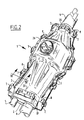
- Figures 1 and 2 show a cable sleeve 1 comprising two metal shells 2,3 which together form a housing, the inner space of which is accessible to a number of cables 4,5,6.
- the internal structure and the manner of coupling of the cables are of no significance to the present invention.
- Each shell 2,3 consists of galvanized steel.
- the lower shell 3 comprises a number of lips which for the sake of convenience are all designated by 7 and which have a general T-shape with widened press-on surface.
- the lips 7 can be bent as according to arrows 8 such that the respective side edges 9,10,11,12 of shells 2,3, after being placed on each other, can be mutually connected with the bent lips.
- Figure 2 shows the manner in which this coupling can take place.
- Figure 1 shows that the lips 7 are bent out of the main plane of the edges 9,10, for instance through almost 90 degrees, whereby good positioning of the edges 11,12 can be realized easily.
- Foam material sealing strips 13,14 have respective shapes corresponding with those of edges 9,10. They are provided locally with widened portions 15 which each have a cut 16 which can co-act in positioning manner with a relevant lip 7.
- the shell 3 has a filling opening 17 in a flat shell part 18 to be described with reference to figure 5.
- the end zones of shells 2,3 are provided with slotted holes generally designated 19 into which fit protrusions 20 which form part of collars 21,22 embodied in divided form. These collars have through-holes 23 for passage of cables 4,5,6.
- the protrusions 20 are provided with information.
- the parts of which collars 21,22 consist can advantageously be wholly symmetrical. They can be embodied in plastic whereby the information can be arranged in relief via the injection moulding process.
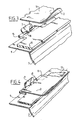
- Figure 3 shows the manner in which a sealing strip 13 is positioned. After placing of the shell 2, the lips 7 can be bent in the manner shown in figure 4 as according to arrow 8.
- FIG. 5 shows that into the through-hole 17 an annular insert piece 24 has been snapped which is provided with internal screw thread 25.
- a screw cap 26 can co-act herewith.
- Both insert piece 24 and screw cap 26 can be made of plastic by injection moulding. Similarly to protrusions 20, the outer surface of these components can carry information in relief.
- the opening 17 serves for filling of an assembled sleeve with filling mass.
- a filling mass is generally supplied in a flexible bag or pouch.
- This pouch can easily be fixed to the sleeve in order to enable filling without spillage.
- a bag clamp can be used for this purpose which consists for instance of a plastic such as polypropylene.
- This injection moulded component is fixed to the corner point of the pouch and then clicked onto the annular insert piece 24.
- the pouch can thereafter be cut through in per se known manner and emptied into the sleeve. After emptying, the bag clamp can again be released.
Landscapes
- Cable Accessories (AREA)
- Flexible Shafts (AREA)
- Laying Of Electric Cables Or Lines Outside (AREA)
- Insulating Bodies (AREA)
- Communication Cables (AREA)
- Control Of Motors That Do Not Use Commutators (AREA)
- Installation Of Indoor Wiring (AREA)
- Details Of Connecting Devices For Male And Female Coupling (AREA)
Claims (10)
- Kabelmuffe, bestehend aus zwei Blech-Metallschalen, die durch Kuppelmittel miteinander gekuppelt werden können, um ein Gehäuse zu bilden, dessen Innenraum für mindestens eine Kabelader über mindestens eine Öffnung zugänglich ist, die von Kantenbereichen beider Schalen umgrenzt wird, wobei die Kuppelmittel aus mehreren an den Kanten von mindestens einer der Schalen vorhandenen Lippen bestehen, die jeweils um die gegenüberliegende Kante der anderen Schale gebogen werden können,
dadurch gekennzeichnet, daß jede Lippe einen schwächeren Bereich aufweist, der als Biegebereich dient, und einen Endbereich mit verbreiterter Oberfläche aufweist. - Kabelmuffe nach Anspruch 1, gekennzeichnet durch einen zusammendrückbaren Dichtungsstreifen, beispielsweise aus Schaumstoff, der zwischen den einander zugewandten Kantenbereichen beider Schalen angeordnet ist.
- Kabelmuffe nach Anspruch 2, dadurch gekennzeichnet, daß der Dichtungsstreifen durchgehende Löcher, z. B. Einschnitte, aufweist, um mindestens eine Reihe von Lippen durchzulassen und so durch sie positioniert zu werden.
- Kabelmuffe nach den Ansprüchen 2 und 3, dadurch gekennzeichnet, daß sich jede Lippe im rechten Winkel zu den genannten einander zugewandten Endbereichen erstreckt.
- Kabelmuffe nach den Ansprüchen 1 bis 4, dadurch gekennzeichnet, daß mindestens eine Schale eine Öffnung hat, um Füllmasse einzulassen, wobei in diese Öffnung durch Einschnappen ein Kunststoffring eingesetzt wird, der mit einer Abdeckung verschließbar ist, z. B. mit einer Schraubenabdeckung, z. B. aus Kunststoff.
- Kabelmuffe nach Anspruch 5, dadurch gekennzeichnet, daß die Öffnung in einem flachen Blechabschnitt ausgeführt ist.
- Kabelmuffe nach den Ansprüchen 1 bis 6, dadurch gekennzeichnet, daß der Kantenbereich einer Schale eine Öse aufweist, durch die eine relativ breite und damit feste Lippe der anderen Schale gesteckt werden kann, um mit ihr ein Scharnier zu bilden.
- Kabelmuffe nach den Ansprüchen 1 bis 7, gekennzeichnet durch Befestigungsmittel zur Befestigung eines Kabels an der Kabelmuffe, wobei diese Befestigungsmittel aus einer Fassung bestehen, die aus zwei zusammenwirkenden Teilen besteht.
- Kabelmuffe nach Anspruch 8, dadurch gekennzeichnet, daß die Fassung mindestens einen Vorsprung aufweist, der in ein in einer Schale vorhandenes Loch paßt.
- Kabelmuffe nach den Ansprüchen 1 bis 9, dadurch gekennzeichnet, daß es sich bei dem Blech um Aluminium handelt.
Priority Applications (6)
| Application Number | Priority Date | Filing Date | Title |
|---|---|---|---|
| DE69604776T DE69604776T2 (de) | 1996-04-12 | 1996-04-12 | Kabelmuffe |
| DK96200916T DK0801454T3 (da) | 1996-04-12 | 1996-04-12 | Kabelmuffe |
| EP96200916A EP0801454B1 (de) | 1996-04-12 | 1996-04-12 | Kabelmuffe |
| ES96200916T ES2137619T3 (es) | 1996-04-12 | 1996-04-12 | Casquillo para cables. |
| AT96200916T ATE185933T1 (de) | 1996-04-12 | 1996-04-12 | Kabelmuffe |
| GR20000400038T GR3032340T3 (en) | 1996-04-12 | 2000-01-12 | Cable sleeve |
Applications Claiming Priority (1)
| Application Number | Priority Date | Filing Date | Title |
|---|---|---|---|
| EP96200916A EP0801454B1 (de) | 1996-04-12 | 1996-04-12 | Kabelmuffe |
Publications (2)
| Publication Number | Publication Date |
|---|---|
| EP0801454A1 EP0801454A1 (de) | 1997-10-15 |
| EP0801454B1 true EP0801454B1 (de) | 1999-10-20 |
Family
ID=8223846
Family Applications (1)
| Application Number | Title | Priority Date | Filing Date |
|---|---|---|---|
| EP96200916A Expired - Lifetime EP0801454B1 (de) | 1996-04-12 | 1996-04-12 | Kabelmuffe |
Country Status (6)
| Country | Link |
|---|---|
| EP (1) | EP0801454B1 (de) |
| AT (1) | ATE185933T1 (de) |
| DE (1) | DE69604776T2 (de) |
| DK (1) | DK0801454T3 (de) |
| ES (1) | ES2137619T3 (de) |
| GR (1) | GR3032340T3 (de) |
Families Citing this family (1)
| Publication number | Priority date | Publication date | Assignee | Title |
|---|---|---|---|---|
| BE1017965A3 (fr) | 2008-01-22 | 2010-02-02 | Sadinter Sogecomex | Boite et procede de jonction. |
Family Cites Families (5)
| Publication number | Priority date | Publication date | Assignee | Title |
|---|---|---|---|---|
| DE855599C (de) * | 1946-07-13 | 1952-11-13 | British Insulated Callenders | Kabelmuffe |
| US2930835A (en) * | 1955-09-29 | 1960-03-29 | Minnesota Mining & Mfg | Removable splice protector |
| US3255302A (en) * | 1965-01-19 | 1966-06-07 | Burndy Corp | Molded insulation casing |
| US4647713A (en) * | 1984-10-25 | 1987-03-03 | Nijs Jacob De | Pressurized telecommunication cable joint closure method and apparatus |
| US4743209A (en) * | 1986-05-21 | 1988-05-10 | Penn Central Telecommunications Company | Compartmentalized splice case |
-
1996
- 1996-04-12 AT AT96200916T patent/ATE185933T1/de not_active IP Right Cessation
- 1996-04-12 ES ES96200916T patent/ES2137619T3/es not_active Expired - Lifetime
- 1996-04-12 DK DK96200916T patent/DK0801454T3/da active
- 1996-04-12 EP EP96200916A patent/EP0801454B1/de not_active Expired - Lifetime
- 1996-04-12 DE DE69604776T patent/DE69604776T2/de not_active Expired - Fee Related
-
2000
- 2000-01-12 GR GR20000400038T patent/GR3032340T3/el unknown
Also Published As
| Publication number | Publication date |
|---|---|
| ES2137619T3 (es) | 1999-12-16 |
| DE69604776D1 (de) | 1999-11-25 |
| DE69604776T2 (de) | 2000-08-10 |
| ATE185933T1 (de) | 1999-11-15 |
| DK0801454T3 (da) | 2000-03-27 |
| EP0801454A1 (de) | 1997-10-15 |
| GR3032340T3 (en) | 2000-04-27 |
Similar Documents
| Publication | Publication Date | Title |
|---|---|---|
| US5574254A (en) | Water-proof sealing structure for an electric junction box | |
| US5796041A (en) | Waterproof protective cover | |
| EP1625808B1 (de) | Interdentalbürste und herstellungsverfahren dafür | |
| US4902855A (en) | End seal for splice closure | |
| US4604800A (en) | Sealing construction for a casing | |
| EP0624933A3 (de) | Koaxialer Verbinder für Koaxialkabel mit einem gewellten Aussenleiter. | |
| US20020026709A1 (en) | Manufacture of a wiring loom | |
| US5636904A (en) | Brush construction | |
| EP0244514B2 (de) | Verfahren und Vorrichtung zum Wasser- und Gasdichtmachen einer Kabel- und/oder Rohrdurchführung einer Wand oder etwas Ähnliches mit Hilfe eines aufschäumbaren synthetischen Harzes | |
| EP0801454B1 (de) | Kabelmuffe | |
| JPH1186840A (ja) | バッテリ用接続具 | |
| IE791341L (en) | Closure sealing element | |
| US4704840A (en) | Mold and method of use | |
| US3203544A (en) | Dispenser for thermosetting resin impregnated tape | |
| EP0899843A2 (de) | Blende mit mindestens eine Einführung, und eine Verteilerdose mit einer solchen Blende | |
| EP0774819B1 (de) | Gehäuse für elektrische Geräte | |
| JPH017980Y2 (de) | ||
| US7069879B1 (en) | Animal toenail cap | |
| JP2532150Y2 (ja) | 包装用缶のキャップの構造 | |
| JPS6029812Y2 (ja) | 防水用タ−ミナルキヤツプ | |
| JP3050806B2 (ja) | ケーブルクロージャ用グロメット | |
| JPH11111362A (ja) | シール装置 | |
| JPH09284970A (ja) | 配線ユニットケーブル用ジョイントボックス及びその製造方法 | |
| JPS629424Y2 (de) | ||
| JPH09100917A (ja) | シールラバー連結部材 |
Legal Events
| Date | Code | Title | Description |
|---|---|---|---|
| PUAI | Public reference made under article 153(3) epc to a published international application that has entered the european phase |
Free format text: ORIGINAL CODE: 0009012 |
|
| AK | Designated contracting states |
Kind code of ref document: A1 Designated state(s): AT BE CH DE DK ES FR GB GR IE IT LI LU MC NL PT SE |
|
| 17P | Request for examination filed |
Effective date: 19980320 |
|
| GRAG | Despatch of communication of intention to grant |
Free format text: ORIGINAL CODE: EPIDOS AGRA |
|
| 17Q | First examination report despatched |
Effective date: 19980728 |
|
| GRAG | Despatch of communication of intention to grant |
Free format text: ORIGINAL CODE: EPIDOS AGRA |
|
| GRAH | Despatch of communication of intention to grant a patent |
Free format text: ORIGINAL CODE: EPIDOS IGRA |
|
| GRAH | Despatch of communication of intention to grant a patent |
Free format text: ORIGINAL CODE: EPIDOS IGRA |
|
| GRAA | (expected) grant |
Free format text: ORIGINAL CODE: 0009210 |
|
| AK | Designated contracting states |
Kind code of ref document: B1 Designated state(s): AT BE CH DE DK ES FR GB GR IE IT LI LU MC NL PT SE |
|
| REF | Corresponds to: |
Ref document number: 185933 Country of ref document: AT Date of ref document: 19991115 Kind code of ref document: T |
|
| REG | Reference to a national code |
Ref country code: CH Ref legal event code: EP |
|
| REG | Reference to a national code |
Ref country code: CH Ref legal event code: NV Representative=s name: ARNOLD & SIEDSMA AG |
|
| REF | Corresponds to: |
Ref document number: 69604776 Country of ref document: DE Date of ref document: 19991125 |
|
| ET | Fr: translation filed | ||
| REG | Reference to a national code |
Ref country code: ES Ref legal event code: FG2A Ref document number: 2137619 Country of ref document: ES Kind code of ref document: T3 |
|
| REG | Reference to a national code |
Ref country code: IE Ref legal event code: FG4D |
|
| REG | Reference to a national code |
Ref country code: PT Ref legal event code: SC4A Free format text: AVAILABILITY OF NATIONAL TRANSLATION Effective date: 19991020 |
|
| REG | Reference to a national code |
Ref country code: DK Ref legal event code: T3 |
|
| PGFP | Annual fee paid to national office [announced via postgrant information from national office to epo] |
Ref country code: IE Payment date: 20000329 Year of fee payment: 5 |
|
| PGFP | Annual fee paid to national office [announced via postgrant information from national office to epo] |
Ref country code: PT Payment date: 20000330 Year of fee payment: 5 |
|
| PGFP | Annual fee paid to national office [announced via postgrant information from national office to epo] |
Ref country code: GB Payment date: 20000403 Year of fee payment: 5 |
|
| PGFP | Annual fee paid to national office [announced via postgrant information from national office to epo] |
Ref country code: DK Payment date: 20000427 Year of fee payment: 5 Ref country code: AT Payment date: 20000427 Year of fee payment: 5 |
|
| PGFP | Annual fee paid to national office [announced via postgrant information from national office to epo] |
Ref country code: NL Payment date: 20000428 Year of fee payment: 5 Ref country code: MC Payment date: 20000428 Year of fee payment: 5 Ref country code: LU Payment date: 20000428 Year of fee payment: 5 Ref country code: FR Payment date: 20000428 Year of fee payment: 5 Ref country code: DE Payment date: 20000428 Year of fee payment: 5 |
|
| PGFP | Annual fee paid to national office [announced via postgrant information from national office to epo] |
Ref country code: SE Payment date: 20000502 Year of fee payment: 5 Ref country code: GR Payment date: 20000502 Year of fee payment: 5 |
|
| PGFP | Annual fee paid to national office [announced via postgrant information from national office to epo] |
Ref country code: ES Payment date: 20000504 Year of fee payment: 5 |
|
| PGFP | Annual fee paid to national office [announced via postgrant information from national office to epo] |
Ref country code: CH Payment date: 20000505 Year of fee payment: 5 |
|
| PGFP | Annual fee paid to national office [announced via postgrant information from national office to epo] |
Ref country code: BE Payment date: 20000508 Year of fee payment: 5 |
|
| PLBE | No opposition filed within time limit |
Free format text: ORIGINAL CODE: 0009261 |
|
| STAA | Information on the status of an ep patent application or granted ep patent |
Free format text: STATUS: NO OPPOSITION FILED WITHIN TIME LIMIT |
|
| 26N | No opposition filed | ||
| PG25 | Lapsed in a contracting state [announced via postgrant information from national office to epo] |
Ref country code: LU Free format text: LAPSE BECAUSE OF NON-PAYMENT OF DUE FEES Effective date: 20010412 Ref country code: IE Free format text: LAPSE BECAUSE OF NON-PAYMENT OF DUE FEES Effective date: 20010412 Ref country code: GB Free format text: LAPSE BECAUSE OF NON-PAYMENT OF DUE FEES Effective date: 20010412 Ref country code: DK Free format text: LAPSE BECAUSE OF NON-PAYMENT OF DUE FEES Effective date: 20010412 Ref country code: AT Free format text: LAPSE BECAUSE OF NON-PAYMENT OF DUE FEES Effective date: 20010412 |
|
| PG25 | Lapsed in a contracting state [announced via postgrant information from national office to epo] |
Ref country code: SE Free format text: LAPSE BECAUSE OF NON-PAYMENT OF DUE FEES Effective date: 20010413 |
|
| PG25 | Lapsed in a contracting state [announced via postgrant information from national office to epo] |
Ref country code: ES Free format text: LAPSE BECAUSE OF NON-PAYMENT OF DUE FEES Effective date: 20010414 |
|
| PG25 | Lapsed in a contracting state [announced via postgrant information from national office to epo] |
Ref country code: MC Free format text: LAPSE BECAUSE OF NON-PAYMENT OF DUE FEES Effective date: 20010430 Ref country code: FR Free format text: THE PATENT HAS BEEN ANNULLED BY A DECISION OF A NATIONAL AUTHORITY Effective date: 20010430 Ref country code: BE Free format text: LAPSE BECAUSE OF NON-PAYMENT OF DUE FEES Effective date: 20010430 |
|
| PG25 | Lapsed in a contracting state [announced via postgrant information from national office to epo] |
Ref country code: LI Free format text: LAPSE BECAUSE OF NON-PAYMENT OF DUE FEES Effective date: 20010511 Ref country code: CH Free format text: LAPSE BECAUSE OF NON-PAYMENT OF DUE FEES Effective date: 20010511 |
|
| BERE | Be: lapsed |
Owner name: LOVINK TERBORG B.V. Effective date: 20010430 |
|
| PG25 | Lapsed in a contracting state [announced via postgrant information from national office to epo] |
Ref country code: PT Free format text: LAPSE BECAUSE OF NON-PAYMENT OF DUE FEES Effective date: 20011031 Ref country code: GR Free format text: LAPSE BECAUSE OF NON-PAYMENT OF DUE FEES Effective date: 20011031 |
|
| PG25 | Lapsed in a contracting state [announced via postgrant information from national office to epo] |
Ref country code: NL Free format text: LAPSE BECAUSE OF NON-PAYMENT OF DUE FEES Effective date: 20011101 |
|
| EUG | Se: european patent has lapsed |
Ref document number: 96200916.3 |
|
| REG | Reference to a national code |
Ref country code: DK Ref legal event code: EBP |
|
| GBPC | Gb: european patent ceased through non-payment of renewal fee |
Effective date: 20010412 |
|
| REG | Reference to a national code |
Ref country code: CH Ref legal event code: PL |
|
| NLV4 | Nl: lapsed or anulled due to non-payment of the annual fee |
Effective date: 20011101 |
|
| PG25 | Lapsed in a contracting state [announced via postgrant information from national office to epo] |
Ref country code: DE Free format text: LAPSE BECAUSE OF NON-PAYMENT OF DUE FEES Effective date: 20020201 |
|
| REG | Reference to a national code |
Ref country code: FR Ref legal event code: ST |
|
| REG | Reference to a national code |
Ref country code: IE Ref legal event code: MM4A |
|
| REG | Reference to a national code |
Ref country code: PT Ref legal event code: MM4A Free format text: LAPSE DUE TO NON-PAYMENT OF FEES Effective date: 20011031 |
|
| REG | Reference to a national code |
Ref country code: ES Ref legal event code: FD2A Effective date: 20030303 |
|
| PG25 | Lapsed in a contracting state [announced via postgrant information from national office to epo] |
Ref country code: IT Free format text: LAPSE BECAUSE OF NON-PAYMENT OF DUE FEES Effective date: 20050412 |