EP0244514B2 - Verfahren und Vorrichtung zum Wasser- und Gasdichtmachen einer Kabel- und/oder Rohrdurchführung einer Wand oder etwas Ähnliches mit Hilfe eines aufschäumbaren synthetischen Harzes - Google Patents
Verfahren und Vorrichtung zum Wasser- und Gasdichtmachen einer Kabel- und/oder Rohrdurchführung einer Wand oder etwas Ähnliches mit Hilfe eines aufschäumbaren synthetischen Harzes Download PDFInfo
- Publication number
- EP0244514B2 EP0244514B2 EP86201856A EP86201856A EP0244514B2 EP 0244514 B2 EP0244514 B2 EP 0244514B2 EP 86201856 A EP86201856 A EP 86201856A EP 86201856 A EP86201856 A EP 86201856A EP 0244514 B2 EP0244514 B2 EP 0244514B2
- Authority
- EP
- European Patent Office
- Prior art keywords
- wall
- cap
- cable
- passage
- cover element
- Prior art date
- Legal status (The legal status is an assumption and is not a legal conclusion. Google has not performed a legal analysis and makes no representation as to the accuracy of the status listed.)
- Expired - Lifetime
Links
- 238000000034 method Methods 0.000 title claims abstract description 15
- 229920003002 synthetic resin Polymers 0.000 title claims abstract description 9
- 239000000057 synthetic resin Substances 0.000 title claims abstract description 9
- 238000004078 waterproofing Methods 0.000 title claims abstract description 5
- 229920005989 resin Polymers 0.000 claims abstract description 18
- 239000011347 resin Substances 0.000 claims abstract description 18
- 238000007789 sealing Methods 0.000 claims description 15
- 239000000463 material Substances 0.000 claims description 14
- 238000005187 foaming Methods 0.000 claims description 7
- 239000007788 liquid Substances 0.000 claims description 4
- 229920002457 flexible plastic Polymers 0.000 claims description 2
- 239000004033 plastic Substances 0.000 description 6
- 229920003023 plastic Polymers 0.000 description 6
- -1 polyethylene Polymers 0.000 description 2
- 239000002689 soil Substances 0.000 description 2
- 238000004804 winding Methods 0.000 description 2
- 239000004698 Polyethylene Substances 0.000 description 1
- 239000004743 Polypropylene Substances 0.000 description 1
- 244000223014 Syzygium aromaticum Species 0.000 description 1
- 235000016639 Syzygium aromaticum Nutrition 0.000 description 1
- 239000002390 adhesive tape Substances 0.000 description 1
- 239000004568 cement Substances 0.000 description 1
- 238000004140 cleaning Methods 0.000 description 1
- 230000000694 effects Effects 0.000 description 1
- 239000006260 foam Substances 0.000 description 1
- 238000002347 injection Methods 0.000 description 1
- 239000007924 injection Substances 0.000 description 1
- 238000009434 installation Methods 0.000 description 1
- 238000012986 modification Methods 0.000 description 1
- 230000004048 modification Effects 0.000 description 1
- 229920000573 polyethylene Polymers 0.000 description 1
- 229920001155 polypropylene Polymers 0.000 description 1
- 230000000717 retained effect Effects 0.000 description 1
- 239000004576 sand Substances 0.000 description 1
- 229920002994 synthetic fiber Polymers 0.000 description 1
Images

Classifications
-
- F—MECHANICAL ENGINEERING; LIGHTING; HEATING; WEAPONS; BLASTING
- F16—ENGINEERING ELEMENTS AND UNITS; GENERAL MEASURES FOR PRODUCING AND MAINTAINING EFFECTIVE FUNCTIONING OF MACHINES OR INSTALLATIONS; THERMAL INSULATION IN GENERAL
- F16L—PIPES; JOINTS OR FITTINGS FOR PIPES; SUPPORTS FOR PIPES, CABLES OR PROTECTIVE TUBING; MEANS FOR THERMAL INSULATION IN GENERAL
- F16L5/00—Devices for use where pipes, cables or protective tubing pass through walls or partitions
- F16L5/02—Sealing
-
- H—ELECTRICITY
- H02—GENERATION; CONVERSION OR DISTRIBUTION OF ELECTRIC POWER
- H02G—INSTALLATION OF ELECTRIC CABLES OR LINES, OR OF COMBINED OPTICAL AND ELECTRIC CABLES OR LINES
- H02G3/00—Installations of electric cables or lines or protective tubing therefor in or on buildings, equivalent structures or vehicles
- H02G3/22—Installations of cables or lines through walls, floors or ceilings, e.g. into buildings
Definitions
- the present invention relates to a method of waterproofing and gastightening a cable or tube passage or hole in a wall or the like, using a foamable synthetic resin, wherein a cover element, e.g. a cap is attached to one side face of the wall to cover the passage or hole, after which, through an opening in said cap the foamable resin is supplied therein and the opening is closed.
- a cover element e.g. a cap is attached to one side face of the wall to cover the passage or hole, after which, through an opening in said cap the foamable resin is supplied therein and the opening is closed.
- a similar method is known from FR-A-2,406,903 in which first a hull is placed in the passage in the wall and later on the cap, which has a depending skirt, is placed at which a shoulder of the cap abuts said hull and wall passage.
- the present invention provides a method in which the cap is only attached to the said one side face of the wall to surround the passage by placing a sealing ring of an open-celled material between the cap and the wall, pressing the cap with the sealing ring against the wall and attaching the cap to the cable or tube by means of a thread or filament, such that the cap is so attached in a fluid-tight manner, that when the foaming resin is supplied it fills up and seals the space between the surface of the passage or hole in the wall and the cable or tube and obtains a good adherence to said one side face of the wall around the passage.
- the advantage of this method is that a properly adhering and waterproof and gastight cable and/or tube passage can be obtained in a relatively simple manner. This is especially important as the work has often to be carried out under difficult conditions. It is sufficient to drill a hole in a wall, to clean the surroundings of the hole on said one side of the wall, to fit the cable through the wall and the tube, to make the connections to the inner cable and, in the case of a gas pipe passage, to make the connection to the inner pipes, to attach the cap to the cable or tube to pour the foamable resin into the cap and to close the opening in the cap.
- the present invention further relates to an apparatus for performing the above described method and is characterized in that the cover element is a flexible plastics conical cap which is provided with aperture means for passing a cable or tube and with a closable filling hole and is capable of receiving and containing a foamable resin, said cap having a rim provided with a sealing ring of an open-celled material as well as attachment means near the cable or tube passing for holding said rim and sealing ring in engagement with only one side face of the wall by attachment to the cable or tube.
- the cover element is a flexible plastics conical cap which is provided with aperture means for passing a cable or tube and with a closable filling hole and is capable of receiving and containing a foamable resin, said cap having a rim provided with a sealing ring of an open-celled material as well as attachment means near the cable or tube passing for holding said rim and sealing ring in engagement with only one side face of the wall by attachment to the cable or tube.
- Such a cap can be attached to the cable passed through by means of a thread or filament of synthetic plastics, rubber or like material.
- a thread or filament of synthetic plastics, rubber or like material.
- this may be provided with an axial split containing means for interconnecting the respective axial longitudinal edges of the split.
- Said means may take the form of an H-section member, and pins for interconnecting the axial longitudinal edges of the split via aligned openings in said longitudinal edges and the H-section.
- the cap may be provided with a graduation.
- the cap described above can also be employed to provide a closure in a pipe, tube or wall bushing or the like, using two spaced apart caps to be installed in the hole concerned.
- the wall has to be cleaned around the opening, so as to obtain a good adherence of the foamed synthetic resin to the wall.
- a passage or hole 9 is drilled in a wall 11, after which a tube 4, whose end that comes to lie in the outside soil 12 is stopped (not shown), is pushed or hammered outwards through the hole (in the drawing from the right to the left).
- the stopper ensures that the tube is not clogged with soil, grit or sand.
- the tube 4 is pushed or hammered so far into the wall that the edge 17 is located between the inner surface and the outer surface of the wall 11.
- the tube stopper (not shown) is now removed, so that an outer cable 5 can be pushed through tube 4 inwards.
- a foamable resin 8 is poured into cap 1, 2, to which end first a stopper 10 is removed, after which the foamable resin 8, e.g. a two-component resin, is poured into cap 1, 2 whereafter stopper 10 is reinstated.
- Cap 1, 2 should be installed in such a manner that the volume of the quantity of resin poured into cap 1, 2 does not exceed the volume enclosed by the inner surface of wall 11 and cap 1, with the level of the liquid resin remaining below the lower edge of hole 9, since otherwise the not-yet-foaming resin will leak away into hole 9, with the result that the space between wall 11 and cap 1, 2 and the space in hole 9 and between the inner wall of tube 4 and the outer cable 5 and between tube 4 and the inner wall of hole 9 is not completely filled with foam 8 so that the waterproofness is not ensured.
- the foaming resin 8 When cap 1, 2 is installed properly, the foaming resin 8 will first entirely fill up the space between cap and wall, and subsequently penetrate into hole 9 and tube 4, between the inner wall of tube 4 and the outer cable 5.
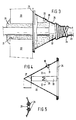
- Fig. 2 shows a different embodiment of cap 1, 2.
- the difference from the cap shown in Fig. 1 is that the connectors 15 are situated in a space 16 formed by means of a cover 19 outside cap 1, 2.
- the cover is connected to cap 1, 2 in a conventional manner, not shown.
- the connectors can now be covered separately: this embodiment. however, has the advantage that the connectors do not lie in the foamed synthetic resin and thereby remain "easily" accessible.
- Figs. 3-5 show an embodiment according to the invention of the application of a conical cap 20 in sealing a passage 21 in a wall 22.
- a conical cap 20 is attached to the cable 23 by means of a flexible synthetic plastics thread or filament (e.g. of PVC).
- the thread or filament is fastened to cable 23 by means of a clove hitch or the like and subsequently filling up the space between the first turn and the conical front of the cap by adjoining turns.
- the conical cap 20 is pressed against the wall 22.
- Proper sealing relative to the wall can be accomplished by fitting the rim of the conical cap with a sealing ring 25 of open-celled material.
- the end of wire 24 is attached to the conical cap by taping the "knot" with a tape diagrammatically shown at 26, which can also ensure a sealing of the cap end relative to cable 23.
- the conical cap is provided with a graduation 32, so that the end of the conical cap can easily be sawn to size.
- the conical cap has a split 27 through which the cap can be easily installed.
- the two longitudinal edges of split 27 are kept together by an H-section member 28 and pins 29 extending through openings, not shown, in the H-section member 28 or the respective edges of the split.
- the conical cap is provided with a filling hole 31 stoppable by a plug 30.
- the conical surface of the cap preferably makes an angle of 45° with the axis of the cap. This makes for a good attachment of the cap relative to the cable or the wall. When this angle is chosen too small, the cap will not be properly pressed against the wall by winding filament 24 around the cable. If, on the other hand, too steep an angle is chosen, the same effect will occur.
- a liquid foamable synthetic resin shown in Fig. 3 in cured condition and indicated at 33
- the filling hole can be stopped or otherwise closed.
- conical cap of flexible synthetic plastics material polyethylene. polypropylene, PVC and the like
- PVC polypropylene
Landscapes
- Engineering & Computer Science (AREA)
- General Engineering & Computer Science (AREA)
- Architecture (AREA)
- Civil Engineering (AREA)
- Structural Engineering (AREA)
- Mechanical Engineering (AREA)
- Installation Of Indoor Wiring (AREA)
- Laying Of Electric Cables Or Lines Outside (AREA)
- Cable Accessories (AREA)
- Processing Of Terminals (AREA)
Claims (7)
- Verfahren zum Wasser- und Gasdichtmachen einer Kabel- (23) oder Rohrdurchführung (21) in einer Wand (22) od.dgl. unter Verwendung eines aufschäumbaren synthetischen Harzes, bei dem ein Abdeckelement (20), beispielsweise eine Kappe an einer Seitenfläche der Wand (22) zur Abdeckung der Durchführung (21) angebracht wird, wonach durch eine Öffnung (31) in dem Abdeckelement (20) in dieses das schäumbare Harz (33) eingebracht und die Öffnung (31) geschlossen wird,dadurch gekennzeichnet,daß das Abdeckelement (20) lediglich an der einen Seitenfläche der Wand (22) angebracht wird, um die Durchführung (21) zu umschließen, indem ein Dichtungsring (25) aus einem offenzelligen Werkstoff zwischen dem Abdeckelement (20) und der Wand (22) angeordnet, das Abdeckelement (20) mit dem Dichtungsring (25) gegen die Wand (22) gepreßt und das Abdeckelement (20) mittels eines Fadens (24) oder einer Faser so am Kabel (23) bzw. Rohr angebracht wird, daß eine flüssigkeitsdichte Befestigung des Abdeckelementes (20) entsteht und beim Einbringen des schäumbaren Harzes (33) dieses den Raum zwischen der Oberfläche der Durchführung (21) in der Wand (22) und dem Kabel (23) bzw. Rohr ausfüllt und abdichtet sowie eine gute Haftung zu dieser einen Seitenfläche der Wand (22) um die Durchführung (21) erreicht wird.
- Verfahren nach Anspruch 1, dadurch gekennzeichnet, daß die Unterseite des Abdeckelementes (20) in ausreichendem Abstand unterhalb der Durchführung (21) vorgesehen wird, so daß das durch die Wand (22) und das Abdeckelement (20) begrenzte und unterhalb der Horizontalebene durch die Unterkante des Durchganges (21) in der Wand (22) liegende Volumen die eingefüllte Menge an flüssigem synthetischem Harz (33) fassen kann.
- Vorrichtung zur Durchführung des Verfahrens nach Anspruch 1 oder 2, dadurch gekennzeichnet, daß das Abdeckelement eine flexible, konische Kunststoffkappe (20) ist, die mit einer Öffnung zur Durchführung eines Kabels (23) bzw. Rohres sowie mit einer verschließbaren Einfüllöffnung (31) versehen ist, wobei diese Abdeckkappe (20) ein schäumbares Harz (33) aufnehmen und fassen kann sowie eine Kante aufweist, die mit einem Dichtungsring (25) aus einem offenzelligen Werkstoff sowie mit einer Befestigungseinrichtung in der Nähe der Durchführung für das Kabel (23) bzw. Rohr versehen ist, und dazu dient, durch Festlegung an dem Kabel (23) bzw. Rohr diese Kante und den Dichtungsring (25) mit lediglich einer Seitenfläche der Wand (22) in Wirkeingriff zu halten.
- Vorrichtung nach Anspruch 3, dadurch gekennzeichnet, daß die Abdeckkappe (20) mit einem axialen Spalt (27) sowie Mitteln (28, 29) versehen ist, um die jeweiligen axialen Längskanten dieses Spaltes (27) miteinander zu verbinden.
- Vorrichtung nach Anspruch 4, gekennzeichnet durch ein Verschlußteil mit H-förmigem Querschnitt sowie mit Stiften zum Verbinden der Längskanten über axial ausgerichtete Öffnungen in den axialen Längenkanten des Spaltes und des Verschlußteils.
- Vorrichtung nach Anspruch 3, 4 oder 5, dadurch gekennzeichnet, daß der Winkel zwischen der Wand der Abdeckkappe und der Achse der konischen Abdeckkappe (20) etwa 45° beträgt.
- Vorrichtung nach Anspruch 3, 4, 5 oder 6, dadurch gekennzeichnet, daß die konische Abdeckkappe (20) mit einer Gradeinteilung (32) versehen ist.
Priority Applications (1)
| Application Number | Priority Date | Filing Date | Title |
|---|---|---|---|
| AT86201856T ATE71777T1 (de) | 1986-05-05 | 1986-10-23 | Verfahren und vorrichtung zum wasser- und gasdichtmachen einer kabel- und/oder rohrdurchfuehrung einer wand oder etwas aehnliches mit hilfe eines aufschaeumbaren synthetischen harzes. |
Applications Claiming Priority (2)
| Application Number | Priority Date | Filing Date | Title |
|---|---|---|---|
| NL8601145 | 1986-05-05 | ||
| NL8601145A NL8601145A (nl) | 1986-05-05 | 1986-05-05 | Werkwijze en inrichting voor het waterdicht afsluiten van een kabel- en/of buisdoorvoeropening in een muur of dergelijke, onder gebruikmaking van een opschuimbaar kunsthars. |
Publications (3)
| Publication Number | Publication Date |
|---|---|
| EP0244514A1 EP0244514A1 (de) | 1987-11-11 |
| EP0244514B1 EP0244514B1 (de) | 1992-01-15 |
| EP0244514B2 true EP0244514B2 (de) | 1996-05-29 |
Family
ID=19847974
Family Applications (1)
| Application Number | Title | Priority Date | Filing Date |
|---|---|---|---|
| EP86201856A Expired - Lifetime EP0244514B2 (de) | 1986-05-05 | 1986-10-23 | Verfahren und Vorrichtung zum Wasser- und Gasdichtmachen einer Kabel- und/oder Rohrdurchführung einer Wand oder etwas Ähnliches mit Hilfe eines aufschäumbaren synthetischen Harzes |
Country Status (7)
| Country | Link |
|---|---|
| US (1) | US4751031A (de) |
| EP (1) | EP0244514B2 (de) |
| AT (1) | ATE71777T1 (de) |
| DE (1) | DE3683488D1 (de) |
| ES (1) | ES2027957T3 (de) |
| GR (1) | GR3003583T3 (de) |
| NL (1) | NL8601145A (de) |
Families Citing this family (14)
| Publication number | Priority date | Publication date | Assignee | Title |
|---|---|---|---|---|
| JPH0297771A (ja) * | 1988-06-03 | 1990-04-10 | Waterproof Coating Sa | 耐水および/またはガス遮断壁に、水密および/または気密なライン・ブッシュを製作するための方法とシーリング剤およびそこに使用される装置 |
| NL8802324A (nl) * | 1988-09-20 | 1990-04-17 | Filoform Chem Ind Bv | Bevestigingsinrichting. |
| DE8913829U1 (de) * | 1989-11-23 | 1990-01-11 | Brandner, Hans, 8240 Schönau | Vorrichtung zum Abdichten eines Kabeldurchführungsloches in einem Schaltschrank |
| CA2071549C (en) * | 1989-12-11 | 2001-02-06 | William L. Welch | Foundation and method for preparing same |
| US5416269A (en) * | 1993-11-01 | 1995-05-16 | Raychem Corporation | Insulated cable and method of making same |
| EP0846238B1 (de) * | 1995-08-23 | 2000-11-02 | Terje Andersen | Feuerfeste stützringe für kabel,rohre und kanalisation |
| EP0890208A1 (de) * | 1996-03-27 | 1999-01-13 | Raychem Limited | Amnordnung und verfahren zum verschliessen einer drahtbündeldurchführung in einer wand oder scheidewand |
| EP0909919A3 (de) * | 1997-10-14 | 2000-03-22 | Carboline Europe Limited | Feuerschutzeinsatz für eingebaute Strahler |
| JP3683727B2 (ja) * | 1998-04-17 | 2005-08-17 | 未来工業株式会社 | 貫通部閉鎖方法 |
| NL1012240C2 (nl) | 1999-06-04 | 2000-12-06 | Filoform Bv | Inrichting en werkwijze voor het afgeven van een afdichtende massa. |
| JP2001346318A (ja) * | 2000-05-31 | 2001-12-14 | Mitsubishi Heavy Ind Ltd | 防爆施設への電線導入構造 |
| US6403889B1 (en) | 2000-05-31 | 2002-06-11 | Tyco Electronics Corporation | Bi-layer covering sheath |
| DE202006011374U1 (de) * | 2006-07-25 | 2006-09-21 | Deutsche Rockwool Mineralwoll Gmbh & Co. Ohg | Wanddurchführung zum Durchführen einer Leitung durch eine Gebäudewandung |
| EP2827041A1 (de) | 2013-07-18 | 2015-01-21 | HILTI Aktiengesellschaft | Isoliermaterial sowie Isolierung für ein Rohr im Bereich einer Wand- oder Deckendurchführung |
Family Cites Families (9)
| Publication number | Priority date | Publication date | Assignee | Title |
|---|---|---|---|---|
| US2892013A (en) * | 1955-05-25 | 1959-06-23 | Douglas Aircraft Co Inc | Bulkhead seal for wire bundles |
| FR2406903A1 (fr) * | 1977-10-18 | 1979-05-18 | Morel Atel Electromec | Procede pour realiser une liaison etanche entre un cable telephonique ou analogue et une canalisation et manchon s'y rapportant |
| DE2841907A1 (de) * | 1978-09-26 | 1980-04-10 | Lentia Gmbh | Thermisch expandierbares dichtungsmaterial fuer fugen, hohlraeume o.dgl. und verfahren zum abdichten von waenden oder tueren im brandfall |
| US4237667A (en) * | 1979-05-02 | 1980-12-09 | Tech-Sil, Inc. | Method and apparatus for installing gel material in architectural barrier breaches |
| US4363199A (en) * | 1980-05-05 | 1982-12-14 | Kennecott Corporation | Fire resistant sealing system for holes in fire resistant building partitions |
| FR2501926A2 (fr) * | 1981-03-13 | 1982-09-17 | Morel Atel Electromec | Procede pour realiser une liaison etanche entre un cable telephonique ou analogue et une canalisation et manchon s'y rapportant |
| US4431198A (en) * | 1982-11-05 | 1984-02-14 | Amp Incorporated | Device for conduit seal and repair |
| US4607469A (en) * | 1984-01-03 | 1986-08-26 | Team, Inc. | Seal for water proofing a utility line conduit and a method of forming the seal |
| DE3411642C2 (de) * | 1984-03-29 | 1987-02-12 | Georg 7920 Heidenheim Walz | Baggergesicherte, elektrisch isolierte Mauerdurchführung für Rohrleitungs-Hauseinführungen |
-
1986
- 1986-05-05 NL NL8601145A patent/NL8601145A/nl not_active Application Discontinuation
- 1986-10-23 AT AT86201856T patent/ATE71777T1/de not_active IP Right Cessation
- 1986-10-23 DE DE8686201856T patent/DE3683488D1/de not_active Expired - Lifetime
- 1986-10-23 ES ES198686201856T patent/ES2027957T3/es not_active Expired - Lifetime
- 1986-10-23 EP EP86201856A patent/EP0244514B2/de not_active Expired - Lifetime
- 1986-10-29 US US06/924,278 patent/US4751031A/en not_active Expired - Fee Related
-
1992
- 1992-01-16 GR GR910402155T patent/GR3003583T3/el unknown
Also Published As
| Publication number | Publication date |
|---|---|
| ATE71777T1 (de) | 1992-02-15 |
| ES2027957T3 (es) | 1992-07-01 |
| EP0244514B1 (de) | 1992-01-15 |
| DE3683488D1 (de) | 1992-02-27 |
| EP0244514A1 (de) | 1987-11-11 |
| GR3003583T3 (en) | 1993-03-16 |
| US4751031A (en) | 1988-06-14 |
| NL8601145A (nl) | 1987-12-01 |
Similar Documents
| Publication | Publication Date | Title |
|---|---|---|
| EP0244514B2 (de) | Verfahren und Vorrichtung zum Wasser- und Gasdichtmachen einer Kabel- und/oder Rohrdurchführung einer Wand oder etwas Ähnliches mit Hilfe eines aufschäumbaren synthetischen Harzes | |
| US6199580B1 (en) | Valve manifold box and method of making same | |
| JPH06351133A (ja) | ワイヤハーネスの防水構造および防水方法 | |
| JPH11266519A (ja) | 壁体への螺旋管体取付け用コネクタ | |
| IT8249729A1 (it) | Mezzo sigillante per un accoppiatore a scatto. | |
| US6237969B1 (en) | Connector for connecting spirally corrugated pipe to wall | |
| US5258572A (en) | Distributing box for underground cables | |
| US9698518B1 (en) | Wire connectors and wire connector kits | |
| ATE155622T1 (de) | Abgedichtete durchführung mit einer biegsamen membrane und einem wegwerfdeckel | |
| US5190408A (en) | Method of laying underground cables | |
| US5198617A (en) | Duct laying fixture for bellows type cable duct | |
| US4785857A (en) | Method and an apparatus for fitting a stopper in a pipe, tube, wall passage or the like, and a container consisting of at least two compartments filled with intermixable substances | |
| US3364299A (en) | Protective enclosure for the junction between a buried utility cable and an underground service lead and method of making same | |
| EP0198528A1 (de) | Verfahren zum Herstellen einer wasserdichten Sperre in einem mehradrigen Kabel oder ähnlichem Leiter und eine zur Durchführung des genannten Verfahrens verwendete Folie | |
| EP0899843A2 (de) | Blende mit mindestens eine Einführung, und eine Verteilerdose mit einer solchen Blende | |
| JPH0461431U (de) | ||
| EP0269586A3 (de) | Inneres Schutzsystem für Behälter, insbesondere unterirdische Behälter für Brennstoff und dergleichen | |
| EP0774819B1 (de) | Gehäuse für elektrische Geräte | |
| GB2096524B (en) | Method and apparatus for attaching a sealing piece over a pour-out hole of a plastics closure cap or container | |
| WO2018101866A1 (en) | Pressure wall bushing kit | |
| JPH0722992Y2 (ja) | 地中埋設ケーブル等の接続用ボックス | |
| JPH017980Y2 (de) | ||
| EP0801454B1 (de) | Kabelmuffe | |
| JPH0512555Y2 (de) | ||
| JPH09196242A (ja) | グロメットの止水構造及び止水方法 |
Legal Events
| Date | Code | Title | Description |
|---|---|---|---|
| PUAI | Public reference made under article 153(3) epc to a published international application that has entered the european phase |
Free format text: ORIGINAL CODE: 0009012 |
|
| AK | Designated contracting states |
Kind code of ref document: A1 Designated state(s): AT BE CH DE ES FR GB GR IT LI LU NL SE |
|
| 17P | Request for examination filed |
Effective date: 19880505 |
|
| 17Q | First examination report despatched |
Effective date: 19900601 |
|
| GRAA | (expected) grant |
Free format text: ORIGINAL CODE: 0009210 |
|
| AK | Designated contracting states |
Kind code of ref document: B1 Designated state(s): AT BE CH DE ES FR GB GR IT LI LU NL SE |
|
| PG25 | Lapsed in a contracting state [announced via postgrant information from national office to epo] |
Ref country code: FR Effective date: 19920115 |
|
| REF | Corresponds to: |
Ref document number: 71777 Country of ref document: AT Date of ref document: 19920215 Kind code of ref document: T |
|
| ET | Fr: translation filed | ||
| ITF | It: translation for a ep patent filed | ||
| REF | Corresponds to: |
Ref document number: 3683488 Country of ref document: DE Date of ref document: 19920227 |
|
| REG | Reference to a national code |
Ref country code: ES Ref legal event code: FG2A Ref document number: 2027957 Country of ref document: ES Kind code of ref document: T3 |
|
| PLBI | Opposition filed |
Free format text: ORIGINAL CODE: 0009260 |
|
| 26 | Opposition filed |
Opponent name: ENDRESS + HAUSER FLOWTEC AG Effective date: 19920921 |
|
| PLAB | Opposition data, opponent's data or that of the opponent's representative modified |
Free format text: ORIGINAL CODE: 0009299OPPO |
|
| REG | Reference to a national code |
Ref country code: GR Ref legal event code: FG4A Free format text: 3003583 |
|
| R26 | Opposition filed (corrected) |
Opponent name: ENDRESS + HAUSER FLOWTEC AG Effective date: 19920921 |
|
| NLR1 | Nl: opposition has been filed with the epo |
Opponent name: HAUSER FLOWTEC AG Opponent name: ENDRESS |
|
| EPTA | Lu: last paid annual fee | ||
| EAL | Se: european patent in force in sweden |
Ref document number: 86201856.1 |
|
| PGFP | Annual fee paid to national office [announced via postgrant information from national office to epo] |
Ref country code: SE Payment date: 19951011 Year of fee payment: 10 |
|
| PGFP | Annual fee paid to national office [announced via postgrant information from national office to epo] |
Ref country code: GR Payment date: 19951013 Year of fee payment: 10 |
|
| PGFP | Annual fee paid to national office [announced via postgrant information from national office to epo] |
Ref country code: ES Payment date: 19951026 Year of fee payment: 10 |
|
| PGFP | Annual fee paid to national office [announced via postgrant information from national office to epo] |
Ref country code: FR Payment date: 19951027 Year of fee payment: 10 |
|
| PUAH | Patent maintained in amended form |
Free format text: ORIGINAL CODE: 0009272 |
|
| STAA | Information on the status of an ep patent application or granted ep patent |
Free format text: STATUS: PATENT MAINTAINED AS AMENDED |
|
| 27A | Patent maintained in amended form |
Effective date: 19960529 |
|
| AK | Designated contracting states |
Kind code of ref document: B2 Designated state(s): AT BE CH DE ES FR GB GR IT LI LU NL SE |
|
| REG | Reference to a national code |
Ref country code: CH Ref legal event code: AEN Free format text: AUFRECHTERHALTUNG DES PATENTES IN GEAENDERTER FORM |
|
| NLR2 | Nl: decision of opposition | ||
| ITF | It: translation for a ep patent filed | ||
| NLR3 | Nl: receipt of modified translations in the netherlands language after an opposition procedure | ||
| PG25 | Lapsed in a contracting state [announced via postgrant information from national office to epo] |
Ref country code: SE Effective date: 19961024 Ref country code: ES Free format text: LAPSE BECAUSE OF THE APPLICANT RENOUNCES Effective date: 19961024 |
|
| EN | Fr: translation not filed | ||
| PG25 | Lapsed in a contracting state [announced via postgrant information from national office to epo] |
Ref country code: GR Free format text: THE PATENT HAS BEEN ANNULLED BY A DECISION OF A NATIONAL AUTHORITY Effective date: 19970430 |
|
| REG | Reference to a national code |
Ref country code: GR Ref legal event code: MM2A Free format text: 3003583 |
|
| EUG | Se: european patent has lapsed |
Ref document number: 86201856.1 |
|
| REG | Reference to a national code |
Ref country code: ES Ref legal event code: FD2A Effective date: 19991007 |
|
| REG | Reference to a national code |
Ref country code: GB Ref legal event code: IF02 |
|
| PGFP | Annual fee paid to national office [announced via postgrant information from national office to epo] |
Ref country code: AT Payment date: 20031027 Year of fee payment: 18 |
|
| PGFP | Annual fee paid to national office [announced via postgrant information from national office to epo] |
Ref country code: CH Payment date: 20041007 Year of fee payment: 19 |
|
| PGFP | Annual fee paid to national office [announced via postgrant information from national office to epo] |
Ref country code: LU Payment date: 20041014 Year of fee payment: 19 |
|
| PG25 | Lapsed in a contracting state [announced via postgrant information from national office to epo] |
Ref country code: AT Free format text: LAPSE BECAUSE OF NON-PAYMENT OF DUE FEES Effective date: 20041023 |
|
| PGFP | Annual fee paid to national office [announced via postgrant information from national office to epo] |
Ref country code: GB Payment date: 20051013 Year of fee payment: 20 |
|
| PGFP | Annual fee paid to national office [announced via postgrant information from national office to epo] |
Ref country code: NL Payment date: 20051018 Year of fee payment: 20 |
|
| PG25 | Lapsed in a contracting state [announced via postgrant information from national office to epo] |
Ref country code: IT Free format text: LAPSE BECAUSE OF NON-PAYMENT OF DUE FEES Effective date: 20051023 |
|
| PG25 | Lapsed in a contracting state [announced via postgrant information from national office to epo] |
Ref country code: LU Free format text: LAPSE BECAUSE OF NON-PAYMENT OF DUE FEES Effective date: 20051031 Ref country code: CH Free format text: LAPSE BECAUSE OF NON-PAYMENT OF DUE FEES Effective date: 20051031 Ref country code: LI Free format text: LAPSE BECAUSE OF NON-PAYMENT OF DUE FEES Effective date: 20051031 |
|
| PGFP | Annual fee paid to national office [announced via postgrant information from national office to epo] |
Ref country code: BE Payment date: 20051123 Year of fee payment: 20 |
|
| PGFP | Annual fee paid to national office [announced via postgrant information from national office to epo] |
Ref country code: DE Payment date: 20051207 Year of fee payment: 20 |
|
| REG | Reference to a national code |
Ref country code: CH Ref legal event code: PL |
|
| PG25 | Lapsed in a contracting state [announced via postgrant information from national office to epo] |
Ref country code: GB Free format text: LAPSE BECAUSE OF EXPIRATION OF PROTECTION Effective date: 20061022 |
|
| PG25 | Lapsed in a contracting state [announced via postgrant information from national office to epo] |
Ref country code: NL Free format text: LAPSE BECAUSE OF EXPIRATION OF PROTECTION Effective date: 20061023 |
|
| REG | Reference to a national code |
Ref country code: GB Ref legal event code: PE20 |
|
| NLV7 | Nl: ceased due to reaching the maximum lifetime of a patent |
Effective date: 20061023 |
|
| BE20 | Be: patent expired |
Owner name: CHEMISCHE INDUSTRIE *FILOFORM B.V. Effective date: 20061023 |