EP0800380B1 - Axle assembly for wheelchair - Google Patents
Axle assembly for wheelchair Download PDFInfo
- Publication number
- EP0800380B1 EP0800380B1 EP95944264A EP95944264A EP0800380B1 EP 0800380 B1 EP0800380 B1 EP 0800380B1 EP 95944264 A EP95944264 A EP 95944264A EP 95944264 A EP95944264 A EP 95944264A EP 0800380 B1 EP0800380 B1 EP 0800380B1
- Authority
- EP
- European Patent Office
- Prior art keywords
- axle
- caster
- wheel
- assembly
- spool
- Prior art date
- Legal status (The legal status is an assumption and is not a legal conclusion. Google has not performed a legal analysis and makes no representation as to the accuracy of the status listed.)
- Expired - Lifetime
Links
Images


Classifications
-
- A—HUMAN NECESSITIES
- A61—MEDICAL OR VETERINARY SCIENCE; HYGIENE
- A61G—TRANSPORT, PERSONAL CONVEYANCES, OR ACCOMMODATION SPECIALLY ADAPTED FOR PATIENTS OR DISABLED PERSONS; OPERATING TABLES OR CHAIRS; CHAIRS FOR DENTISTRY; FUNERAL DEVICES
- A61G5/00—Chairs or personal conveyances specially adapted for patients or disabled persons, e.g. wheelchairs
- A61G5/10—Parts, details or accessories
- A61G5/1056—Arrangements for adjusting the seat
- A61G5/1067—Arrangements for adjusting the seat adjusting the backrest relative to the seat portion
-
- A—HUMAN NECESSITIES
- A61—MEDICAL OR VETERINARY SCIENCE; HYGIENE
- A61G—TRANSPORT, PERSONAL CONVEYANCES, OR ACCOMMODATION SPECIALLY ADAPTED FOR PATIENTS OR DISABLED PERSONS; OPERATING TABLES OR CHAIRS; CHAIRS FOR DENTISTRY; FUNERAL DEVICES
- A61G5/00—Chairs or personal conveyances specially adapted for patients or disabled persons, e.g. wheelchairs
- A61G5/08—Chairs or personal conveyances specially adapted for patients or disabled persons, e.g. wheelchairs foldable
- A61G5/0808—Chairs or personal conveyances specially adapted for patients or disabled persons, e.g. wheelchairs foldable characterised by a particular folding direction
- A61G5/0816—Chairs or personal conveyances specially adapted for patients or disabled persons, e.g. wheelchairs foldable characterised by a particular folding direction folding side to side, e.g. reducing or expanding the overall width of the wheelchair
- A61G5/0825—Chairs or personal conveyances specially adapted for patients or disabled persons, e.g. wheelchairs foldable characterised by a particular folding direction folding side to side, e.g. reducing or expanding the overall width of the wheelchair comprising a scissor-type frame, e.g. having pivoting cross bars for enabling folding
-
- A—HUMAN NECESSITIES
- A61—MEDICAL OR VETERINARY SCIENCE; HYGIENE
- A61G—TRANSPORT, PERSONAL CONVEYANCES, OR ACCOMMODATION SPECIALLY ADAPTED FOR PATIENTS OR DISABLED PERSONS; OPERATING TABLES OR CHAIRS; CHAIRS FOR DENTISTRY; FUNERAL DEVICES
- A61G5/00—Chairs or personal conveyances specially adapted for patients or disabled persons, e.g. wheelchairs
- A61G5/08—Chairs or personal conveyances specially adapted for patients or disabled persons, e.g. wheelchairs foldable
- A61G5/0866—Chairs or personal conveyances specially adapted for patients or disabled persons, e.g. wheelchairs foldable folding down backrest, e.g. where the backrest folds down onto the seat support
-
- A—HUMAN NECESSITIES
- A61—MEDICAL OR VETERINARY SCIENCE; HYGIENE
- A61G—TRANSPORT, PERSONAL CONVEYANCES, OR ACCOMMODATION SPECIALLY ADAPTED FOR PATIENTS OR DISABLED PERSONS; OPERATING TABLES OR CHAIRS; CHAIRS FOR DENTISTRY; FUNERAL DEVICES
- A61G5/00—Chairs or personal conveyances specially adapted for patients or disabled persons, e.g. wheelchairs
- A61G5/10—Parts, details or accessories
- A61G5/1054—Large wheels, e.g. higher than the seat portion
-
- A—HUMAN NECESSITIES
- A61—MEDICAL OR VETERINARY SCIENCE; HYGIENE
- A61G—TRANSPORT, PERSONAL CONVEYANCES, OR ACCOMMODATION SPECIALLY ADAPTED FOR PATIENTS OR DISABLED PERSONS; OPERATING TABLES OR CHAIRS; CHAIRS FOR DENTISTRY; FUNERAL DEVICES
- A61G5/00—Chairs or personal conveyances specially adapted for patients or disabled persons, e.g. wheelchairs
- A61G5/10—Parts, details or accessories
- A61G5/1083—Quickly-removable wheels
-
- A—HUMAN NECESSITIES
- A61—MEDICAL OR VETERINARY SCIENCE; HYGIENE
- A61G—TRANSPORT, PERSONAL CONVEYANCES, OR ACCOMMODATION SPECIALLY ADAPTED FOR PATIENTS OR DISABLED PERSONS; OPERATING TABLES OR CHAIRS; CHAIRS FOR DENTISTRY; FUNERAL DEVICES
- A61G5/00—Chairs or personal conveyances specially adapted for patients or disabled persons, e.g. wheelchairs
- A61G5/10—Parts, details or accessories
- A61G5/1097—Camber- or toe-adjusting means for the drive wheels
-
- A—HUMAN NECESSITIES
- A61—MEDICAL OR VETERINARY SCIENCE; HYGIENE
- A61G—TRANSPORT, PERSONAL CONVEYANCES, OR ACCOMMODATION SPECIALLY ADAPTED FOR PATIENTS OR DISABLED PERSONS; OPERATING TABLES OR CHAIRS; CHAIRS FOR DENTISTRY; FUNERAL DEVICES
- A61G5/00—Chairs or personal conveyances specially adapted for patients or disabled persons, e.g. wheelchairs
- A61G5/10—Parts, details or accessories
- A61G5/12—Rests specially adapted therefor, e.g. for the head or the feet
- A61G5/128—Rests specially adapted therefor, e.g. for the head or the feet for feet
-
- A—HUMAN NECESSITIES
- A61—MEDICAL OR VETERINARY SCIENCE; HYGIENE
- A61G—TRANSPORT, PERSONAL CONVEYANCES, OR ACCOMMODATION SPECIALLY ADAPTED FOR PATIENTS OR DISABLED PERSONS; OPERATING TABLES OR CHAIRS; CHAIRS FOR DENTISTRY; FUNERAL DEVICES
- A61G5/00—Chairs or personal conveyances specially adapted for patients or disabled persons, e.g. wheelchairs
- A61G5/10—Parts, details or accessories
- A61G5/1056—Arrangements for adjusting the seat
- A61G5/1059—Arrangements for adjusting the seat adjusting the height of the seat
-
- Y—GENERAL TAGGING OF NEW TECHNOLOGICAL DEVELOPMENTS; GENERAL TAGGING OF CROSS-SECTIONAL TECHNOLOGIES SPANNING OVER SEVERAL SECTIONS OF THE IPC; TECHNICAL SUBJECTS COVERED BY FORMER USPC CROSS-REFERENCE ART COLLECTIONS [XRACs] AND DIGESTS
- Y10—TECHNICAL SUBJECTS COVERED BY FORMER USPC
- Y10S—TECHNICAL SUBJECTS COVERED BY FORMER USPC CROSS-REFERENCE ART COLLECTIONS [XRACs] AND DIGESTS
- Y10S297/00—Chairs and seats
- Y10S297/04—Wheelchair
Definitions
- the chairs are characterized by their light weight and adjustable wheels.
- the wheels can be adjusted so that their camber can be changed from 0°, that is, with the rear, driving wheels located in a vertical plane, to 12°, or sometimes more, where the top of the wheel is closer to the chair than the bottom of the wheel.
- height of the front caster wheels also needs to be changed to adjust the toe in or toe out of the drive wheels as well as to keep the main pivot axis of each of the caster wheels vertical.
- Wheelchairs come in different heights primarily to accommodate the different lengths of the user's legs. This creates a problem for organizations that must supply wheelchairs to a number of individuals, such as wheelchair rental companies, hospitals and nursing homes. Because of different height requirements, a great number of wheelchairs must be kept in stock to accommodate various users. A number of wheelchairs have been designed so that the height of the main drive wheels can be adjusted in various ways. However, these designs generally require some sort of disassembly of the mounting components using tools, an often cumbersome and time-consuming process.
- US-A-4 351 540 discloses an example of a wheelchair where the angle of the camber can be adjusted.
- the present invention relates to an axle assembly as defined in claim 1.
- a wheelchair frame assembly made according to one aspect of the invention includes a frame having spaced-apart lower portions to which drive wheel axle assemblies and caster wheel assemblies are mounted.
- Each axle assembly includes an axle adjustment member, typically a tube, secured to the frame and an axle housing, defining an axle bore, mounted to the axle adjustment tube at a chosen rotary orientation.
- the chosen rotary orientation determines the camber of the drive wheel mounted to the axle assembly.
- the mounting of the axle housing is accomplished without the use of tools so that the user can manually change the camber of the drive wheel in an extremely simple manner.
- the front to rear position of the axle housing can also be, in one preferred embodiment, adjusted in a toolless manner, typically through the use of a quick release pin designed to engage or disengage various recesses formed in the axle adjustment tube.
- the axle housing preferably includes an axle adjustment block and an adjustable axle lug mounted within a transverse bore formed in the axle adjustment block.
- the axle lug defines an axle bore within which a quick release axle, which passes through the drive wheel, is housed.
- the position of the adjustable axle lug can be changed to move the hub of the drive wheel closer towards or farther away from the frame to accommodate personal preferences and to ensure that the wheel does not rub against the frame as the camber of the drive wheel is changed.
- Changing the camber of the drive wheel requires that the distance between the front end of the frame and the support surface be changed to adjust the toe in or toe out of the drive wheel as well as to ensure that the caster wheel pivot axis remains substantially vertical.
- This is preferably accomplished in a toolless manner by mounting the caster spool of the caster wheel to the frame at various vertical positions using a caster spool housing.
- a quick release pin engages selected indentations or recesses in the caster spool so to lock the caster spool to the caster spool housing at the desired height without the use of tools.
- the caster wheel assembly includes a caster spool having a bore and a caster wheel including a wheel mount, a wheel rotatably secured to the wheel mount and a spindle extending upwardly from the wheel mount into the bore of the caster spool.
- the spindle is rotatably secured within the bore of the caster spool by one or more bearings. Since the bearings are captured between the caster spool and the spindle, and since the entire caster wheel assembly is removed and replaced, removal and replacement can be done without subjecting the user to getting oil and grease on the user's hands and clothes, which could occur if the spindle and bearings were not so enclosed. This constructions also aids in the repair or replacement of any defective bearings since such repair can be done apart from the wheelchair.
- the primary advantage of the invention is that the desired positional adjustments are all simply made without the need for tools; this makes making such adjustments easy and quick. No additional parts, such as shims or washers, are needed to change the camber, height or other position or orientation of the drive wheels or caster wheels. This eliminates the need for carrying such extra parts and the possibility of losing necessary parts.
- Another advantage of the invention is that its simplicity of design and ease of assembly can reduce assembly costs for the manufacturer. This translates into a lower cost chair for the user.
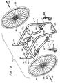
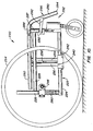
- Fig. 1 illustrates a wheelchair frame assembly 2, most of the components of which are also shown in Fig. 2.
- Assembly 2 includes broadly a frame 4 having a pair of spaced-apart lower frame portions 6, each of which has a rear end 8 and a front end 10.
- a rear frame portion 12 extends upwardly from rear end 8 of lower frame portion 6 and a front frame portion 14 extends upwardly from front end 10 of lower frame portion 6.
- the upper ends of front and rear frame portions 14, 12 are coupled by seat portions 16.
- Seat portions 16 are each pivotally mounted to the upper end of front frame portion 14 at a pivot 18 and adjustably mounted to one of several positions 20 along rear from portion 12 through use of a quick release pin 22.
- Each of the sides of frame 4 are connected by lateral braces 24 and a footrest 26.
- An adjustable seat back support 28, shown in Fig. 1 only, is mounted to the rear end 30 of seat portion 16 and to rear frame portion 12 using a slider 32.
- a seat and backrest are mounted to frame assembly 2 during use but are not
- axle assembly 34 is mounted to each lower frame portion 6 adjacent to rear end 8.
- Axle assembly 34 is used to mount a typically conventional drive wheel 36 using a conventional quick release axle 38 passing through the hub 39 of drive wheel 36.
- Figs. 3 and 3A illustrate axle assembly 34 to include an axle adjustment member or tube 40 having a bore 42 sized to mount over and be secured to lower frame portion 6, typically by glue or other bonding agent.
- Tube 40 has an outer surface 44 including axially extending splines 46 and a series of axially extending, circumferential grooves 48 formed within the splined outer surface 44.
- Axle assembly 34 also includes an axle adjustment block 50 having a transverse bore 52 sized to house a generally cylindrical, adjustable axle lug 54. Together, axle adjustment block 50 and adjustable axle lug 54 constitute an axle housing 56. Lug 54 defines an axle bore 58 within which quick release axle 38 is housed.
- Axle adjustment block 50 also includes a main bore 60 having a splined inner surface 62 constructed to mate with splines 46 on surface 44 of tube 40.
- splined inner surface 62 and splines 46 on surface 44 contain ninety equally spaced splines, each spline spaced 4° apart. Since tube 40 is fixed to lower frame portion 6, the rotary orientation of block 50 relative to tube 40 determines the angular inclination of a drive wheel axis 64 defined by axle bore 58 and thus the cant of wheel 36. To aid the user in the proper rotary orientation of block 50 and tube 40, appropriate alignment lines can be drawn and labeled, for example 0°, 4°, 8°, 12°, on surface 44 of axle adjustment tube 40 for alignment with an appropriate index marker on axle adjustment block 50.
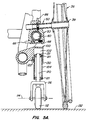
- Block 50 is locked at a front-to-back position along surface 44 of tube 40 through the use of a quick release pin 66 mounted within a blind bore 68 which intersects main bore 60, as shown in Figs. 5A-5C.
- Pin 66 has a full diameter portion 70 and a reduced diameter portion 72, the end of full diameter portion 70 pressing against a compression coil spring 74 which normally biases pin 66 out of blind bore 68.
- a roll pin 76 is pressed into a roll pin hole 78, formed transverse to blind bore 68, to intersect the blind bore and engage a shoulder 80 of pin 66 between portions 70, 72. Accordingly, when quick release pin 66 is in the locked or use position of Fig. 3, full diameter portion 70 is partially within main bore 60 and is in one of grooves 48 formed in surface 48 of tube 40.
- quick release pin 66 To adjust the front/back position of drive wheel 36, the user simply presses on quick release pin 66 so to disengage full diameter portion 70 from groove 48, which permits axle housing 56 to slide along axle adjustment tube 40.
- quick release pin 66 When the desired front/back position is achieved, quick release pin 66 is released and full diameter portion 70 snaps into the groove 48 with which it is aligned.
- Changing the camber of wheel 36 is similar but axle housing 56 is moved in a forward direction until splined inner surface 62 completely disengages splines 46 to permit axle housing 56 to be rotated relative to tube 40 and then slid back onto tube 40 when the proper rotary orientation, and thus the proper camber, is achieved.
- adjustable axle lug 54 has a set of circumferential grooves 84 formed in its outer surface. Grooves 84 are engaged by a quick release pin 86 housed within a blind bore 88 and biased outwardly by compression coil spring 90 in a manner similar to quick release pin 66. Pin 86 is kept from being urged completely out of hole 88 by a roll pin 92. Pressing on quick release pin 86 allows the user to adjust the position of axle lug 54 along drive wheel axis 64, thus changing the location of drive wheel hub 40 relative to frame 4.
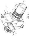
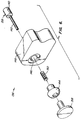
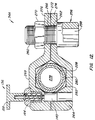
- FIGs. 4 and 4A illustrate a caster wheel assembly 94, including a two-piece caster spool housing 100 having a blind bore 102, see Figs. 5A-5C, within which the generally cylindrical caster spool 104 of caster wheel 98 is housed.
- Housing 100 includes a main portion 106 and a clamping portion 108 which define a cylindrical opening 110 sized to surround lower frame portion 6 adjacent front end 10 so to permit caster spool housing 100 to be clamped firmly to lower frame portion 6 using, for example, screws or bolts (not shown).
- Caster wheel 98 includes a wheel 112 having a generally horizontal axis 114 mounted to a fork-like wheel mount 116 having a clevis portion 118 and a spindle portion 120 coaxial with pivot axis 96 and pivotally housed within caster spool 104 by a pair of bearings 121, preferably ball bearings, although sleeve bearings could also be used.
- Caster wheel assembly 94 also include a quick release pin 122 and a compression spring 124 housed within a blind bore 126 formed in housing 100; pin 122 is maintained within blind bore by a roll pin 128.
- Quick release pin 122 when in its normal outwardly biased position of Fig. 4, engages one of three grooves 130 formed in the outer surface of caster spool 104 to adjust the position of caster spool 104 within blind bore 102 and thus the distance between wheel 112 and lower frame portion 6.
- bearings 121 are captured between spindle portion 120 and housing 100 as a part of caster wheel 98. This not only permits quick height adjustment of caster wheel 98, it makes removal and replacement of the caster wheel much cleaner; the person removing caster wheel 98 is not exposed to the messy grease and oil lubricating the spindle portion and bearings during adjustment or removal and replacement of the caster wheel. Also, if bearings 121 need to be replaced, this can be done easily since caster wheel 98 can be easily removed from the rest of the wheelchair and disassembled by removing spring clip 131 from spindle portion 120 and removing spindle portion 120 from within bearings 121 to provide access to bearings 121.
- caster wheels 98 having different length caster spools 104 and/or different diameter wheels 112 can be easily and quickly installed. This permits a user to change from larger diameter wheels, useful for general use, to smaller diameter wheels, useful for activities, such as basketball, where maximum maneuverability is desired.
- Fig. 5A illustrates drive wheel 36 at a 4° camber.
- quick release pin 122 engages the upper most of grooves 130 to maintain caster wheel pivot axis 96 vertical. It has been found that this upper most groove 130 is also usable when drive wheel 36 is adjusted for a 0° camber; the difference in height of rear end 8 of lower frame portion 6 above support surface 132 when at a 0° camber and a 4° camber is very small (0.25%) so as not to require a separate groove 130 for both the 0° camber and the 4°camber.
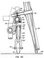
- Figs. 5B and 5C illustrate drive wheel 36 at an 8° camber and a 12° camber, respectively. (Note that in Figs.
- quick release axle 38 is not shown.
- quick release pin 122 engages a still lower groove 130, thus lowering front end 10 of lower frame portion 6 in an amount substantially equal to the distance rear end 8 of lower frame portion 6 is lowered at each of these different camber angles.
- the position of quick release pin 86 within one of groove 84 of adjustable axle lug 54 is not changed. If desired, the position of lug 54 within transverse bore 52 can be changed to change the distance between hub 40 and lower frame portion 6 to accommodate the personal preferences of the user and ensure that top of drive wheel 36 does not rub against or otherwise interfere with frame 4.
- each drive wheel 36 is adjusted by first removing drive wheel 36 from axle assembly 34 by removal of quick release axle 38.
- the rotary orientation of axle assembly 34, and thus the camber of drive wheel 36 is adjusted by pressing on quick release pin 66 and sliding axle housing 56 in a forward direction, that is, towards caster wheel assembly 94, until splines 46 disengage from splined inner surface 62.
- Axle housing 56 is then rotated the appropriate amount and slid back to re-engage splines 46 with splined inner surface 62.
- quick release pin 66 is released to permit full diameter portion 72 to engage the appropriate groove 48, thus locking axle housing 56 in position.
- quick release pin 86 is depressed and adjustable axle lug 54 is moved within transverse bore 52 until properly positioned, at which time pin 86 is released to lock lug 54 in place.
- Drive wheel 36 can then be remounted to axle housing 56 using quick release axle 38 passing through drive wheel hub 39.
- the height of front end 10 of lower frame portion 6 above support surface 132 can be adjusted by pressing on quick release pin 122, moving caster spool 104 within blind bore 102 and releasing quick release pin 122 when aligned with the appropriate groove 130.
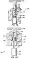
- Figs. 6, 7A and 7B illustrate an alternative embodiment of a quick release pin assembly 136 which can be used in lieu of the quick release pin assemblies discussed above.
- Assembly 136 includes a quick release engagement pin 138 having a larger diameter end 140 and a smaller diameter end 142.
- the assembly also includes a bushing 144 housed within one end of a multi-diameter bore 146 formed in a somewhat generic block 148.
- a coil spring 150 is mounted over end 142 of engagement pin 138.
- One end of spring 150 abuts against an annular ledge 152 formed in bore 146 while the other end of spring 150 abuts against the base 154 of a counterbore 156 formed in a push-button 158.
- End 142 of pin 138 is secured within an axial bore 159, such as through the use of an adhesive or by a friction fit.
- spring 150 is slightly compressed keeping larger diameter end 140 of pin 138 pressing against annular ledge 152.
- larger diameter end 140 can engage one of the various grooves formed in, for example, axle lug 54, axle adjustment tube 40 or caster spool 104. Pressing on push-button 158 compresses spring 150 to move end 138 to the position of Fig. 7B so to disengage pin 138 from the previously engaged groove to permit the appropriate removal or adjustment of the various parts.
- the quick release pin assembly 136 shown in Figs. 6-7B is generally preferred because it requires less space and is easier to make and assemble than the quick release pin assemblies discussed above.
- a further aspect of the invention relates to the ability of the user, while sitting in the wheelchair, to adjust the angle of seat back support 28 relative to rear frame portion 12 without the use of tools.
- FIGs. 8-9D an adjuster assembly 160 by which the angle of seat back support 28 can be adjusted by the user sitting in the wheelchair, without the use of tools, is described.
- Each seat back support 28 is mounted to seat portion 16 of frame 4 by a hinge 162 so that seat back support 28 pivots about a pivot 164.
- an angle adjustment arm 166 is used to couple seat back 28 to rear frame portion 12.
- Adjustment arm 166 is secured at its forward end to an adjustment arm mounting bracket 170.
- a bolt 174 passes freely through a hole in seat back support 28 and a hole in the bracket 170 and engages a nut 175. While the position of bracket 170 along seat back support 28 could be adjusted or changed, in practice it is generally left in one position so that bolt 174, instead of some type of quick release fastener, is used.
- Arm 166 has a number of intersecting, parallel bores 176 having countersunk ends 178, bores 176 being sized for receipt of the tapered end 180 or a release pin 182.
- Release pin 182 is biased toward engagement within bores 176 by a compression spring 184.
- Compression spring 184 is mounted over pin 182 and is captured between the end of a countersunk opening (not shown) formed in an adjustment arm receiver plate 186 and a shoulder 188 adjacent end 180 of pin 182.
- the outer end 190 of release pin 182 is threaded for being fastened to a pull knob 192 to which a lanyard 194 is secured. Pulling on lanyard 194, which can be accomplished by many wheelchair users while seated in the wheelchair, pulls on pull knob 192 so to compress spring 184 and disengage tapered end 180 of release pin 182 from the bore 176 with which it is aligned.
- Adjustment arm 166 is captured between double-tapered faces 196 of an adjustment arm receiver body 198.
- body 198 is a one-piece integral extension of a slide mount body 200.
- Receiver body 198 combines with plate 186 to form an adjustment receiver with the two parts secured together by cap screws 202.
- Slide mount body 200 includes a central bore 204 which houses an anti-scratch liner 206.
- the outer surface 208 of liner 206 adheres to the wall of bore 204 using a suitable adhesive.
- Liner 206 is relatively soft and snugly positions slide mount body 200 about rear frame portion 12.
- Liner 206 is, in the preferred embodiment, a length of looped fabric material sold under the trademark VELCRO®.
- Fig. 9A illustrates seat portion 16 at its topmost position, that is with about a 1" (2.5 centimeter) drop front to back and seat back support 28 generally vertical.
- lanyard 194 is grasped and pulled upwardly which pulls on pull knobs 192 for each adjuster assembly 160. This withdraws tapered end 180 of each release pin 182 from opening 210 formed in adjustment arm receiver body 198 and at least partially from bore 176 to permit seat back support 28 to be pushed rearwardly causing different holes 176 to become aligned with release pin 182.
- lanyard 194 can be released to permit tapered end 180 of release pin 182 to reseat within opening 210 and the appropriately positioned bore 176 and thus lock adjustment arm 166 in position relative to adjuster assembly 160.
- Fig. 9C shows seat back support 28 at the opposite extreme, that is angled 12 degrees forward from a vertical axis as opposed to the 6.5 degree backward lean from a vertical axis of Fig. 9B. This is achieved in the same way, that is by pulling lanyard 194 and urging seat back support 28 in the desired direction, in this case forward.
- the pivotal movement of seat back support 28 is accommodated by the movement of slide mount body 200 along rear frame portion 12. It is not necessary to lock slide mount body 200 to rear frame portion 12 to maintain seat back support 28 in a desired position. This is because once the release pin 182 is fully housed within a bore 176, a rigid triangle is created between pivot point 164, bolt 174 and release pin 182. Since the length of each leg of the triangle is fixed, a rigid structure results.
- Adjuster assembly 160 is shown with adjustment arm 166 extending from seat back support 28. If desired, adjustment arm 166 could extend from rear frame portion 12. Also, regardless of whether adjustment arm 166 extends from seat back support 28 or rear frame portion 12, slide mount body 200 and adjustment arm mounting bracket could be reversed so that slide mount body 200 would be slidable over seat back support 28 and adjustment arm mounting bracket 170 would be fixed to rear frame portion 12.
- lanyard 194 provides a simple and inexpensive means for disengaging the release pins to permit seat back supports to be pivoted forward or rearward. If desired, other types of actuators in lieu of lanyard 194 could be used. Also, seat back support 28 could be spring biased in a forward direction, such as by one of a torsion spring at pivot point 164.
- Fig. 9D illustrates the complete removal of angle adjustment arm 166 from adjustment arm receiver body 198 to permit seat back support 28 to be folded down to a generally horizontal position adjacent seat portion 6, typically for storage or during transport.
- Tapered faces 196 aid guiding angle adjustment arm 166 into receiver body 198.
- Receiver body 198 is made with tapered faces 196 on each side so that a single part, in this case slide mount body 200 and receiver body 198, can be used on the seat back support on either side of the wheelchair.
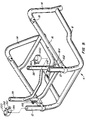
- Wheelchair 220 is shown without the conventional fabric seat or backrest in Fig. 10.
- Wheelchair 220 includes left and right side frame members 222, the right side frame members shown in Fig. 10, the left side frame member being in a mirror image.
- Frame member 222 includes a lower frame portion 224, an upper frame portion 226, a rear frame portion 228 and a front frame portion 230, all welded or otherwise secured together in a generally rectangular configuration.
- Each rear frame portion 228 extends upwardly beyond upper frame portion 226 and accepts a push handle, not shown, between which the fabric backrest, not shown, is usually mounted.
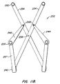
- Frame members 222 are maintained generally parallel to one another using a folding linkage assembly 232, seen best in Figs. 11A-11C.
- Linkage assembly 232 includes a pair of folding cross-bars 234, 236 pivotally connected to one another at their central regions by a pivot 238.
- the lower ends of cross-bars 234, 236 are connected to lower frame portion 224 through a rotating pivot sleeve 240.
- Each pivot sleeve 240 is free to pivot about its lower frame portion 224 but is prevented from moving axially along lower frame portion 224 through the use of stops 242 on either end of pivot sleeve 240.
- Upper frame portions 226 are coupled to cross-bars 234, 236 by links 244, 246, respectively.
- Links 244, 246 are free to pivot at their lower ends about upper frame portions 226 and are pivotally connected to cross-bars 234, 236 by pivot connections 248.
- seat tubes 250 are, as is conventional, used to stretch a fabric seat therebetween when folded linkage assembly 232 is in the fully open or locked out position of Fig. 11A and Fig. 10.
- Wheelchair 220 also includes a pair of front caster wheel assemblies 252 mounted to front frame portions 230.
- Front caster wheel assemblies 252 are generally similar to caster wheel assemblies 94 using quick release pin assemblies 135; because both are described above they will not be described in detail.
- Wheelchair 220 includes a pair of rear or drive wheels 254 of similar construction as drive wheels 36 discussed above. Each drive wheel 254 is mounted to an axle assembly 34A.
- Each axle assembly 34A includes an axle receiver 256, see Fig. 12, sized to receive a quick release axle (not shown in Figs. 10-14) similar to quick release axle 38 shown in Fig. 2.
- axle receiver 256 is essentially a large bolt having a bore 258 formed therethrough for receipt of the quick release axle.
- the threaded end 260 of axle receiver 256 passes through a clearance hole 262 formed in a first axle adjustment bracket 264 and a threaded hole 266 formed in a second axle adjustment bracket 268.
- a jam nut 270 is used to lock axle receiver 256 to second axle adjustment bracket 268 once an appropriate adjustment gap 272 is provided between the axle ends 274, 276 of brackets 264, 268.
- brackets 264, 268 are generally C-shaped and define a hexagonal opening 278 therebetween. Hexagonal opening 278 corresponds to the hexagonal configuration of axle adjustment tube 280 mounted to rear frame portion 228.
- Axle adjustment tube 280 has a series of annular positioning grooves 282 formed along its length and used to position axle receiver 256 at various heights. This is achieved by the use of a quick release pin assembly 136 described above with reference to Figs. 6-7B.
- Pushing on push button 158 causes the larger diameter end 140 to become disengaged from positioning groove 282 to permit axle adjustment brackets 264, 268 and axle receiver 256 therewith to be moved along axle adjustment tube 280 thus changing the height of seat tube 250 relative to the ground surface.
- the change in axle height preferably takes place along with an adjustment of the height of caster wheel assembly 252, a change in the size of the caster wheels 98, or both.
- the hexagonal cross-sectional shape of tube 280 is used to maintain the desired rotary or angular relationship between axle receiver 256 and frame member 222.
- Other methods for doing this such as using D-shaped axle adjustment tubes or a pin and slot configuration, in which a pin extending from one of the brackets 264, 268 or the axle adjustment tube 280 engages a vertical slot in the other of the brackets 264, 268 or tube 280, could be used.
- axle receiver 256 is shown positioned forward of rear frame portion 228. If desired, axle receiver 256 could be positioned rearward of rear frame portion 228 by flipping axle adjustment brackets 264, 268 upside down so that quick release pin assembly 136 is placed forward of frame portion 228.
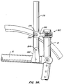
- a footrest is mounted to the lower end 284 of a footrest support 286.
- Footrest support 286 pivots about an axis 287 passing up through the center of front frame portion 230. See Figs. 13 and 14.
- Footrest support 286 has a generally horizontal upper portion 288 which is pivotally supported on the upper end of front frame portion 230 by a rotatable plastic saddle plug 289.
- the downwardly and outwardly extending lower portion 290 of footrest support 286 is supported by a generally horizontal bracket 292 welded thereto.
- the inner end 294 of bracket 292 is positioned adjacent front frame portion 230 and is fastened to a release housing 296 by screws 297.
- Release housing 296 has a C-shaped portion 298 which partially surrounds and slides against front frame portion 230 as support 286 pivots about axis 287. This movement is guided by a quick release pin assembly 136A engaging a quadrant block 300.
- Block 300 is secured to, typically bolted to, front frame portion 230.
- Block 300 has an arcuate slot 302 with enlarged regions 304, 305 at either end. Regions 304, 305 are sized for receipt of larger end 140A of pin 138A so to secure footrest support 286 at either end of its travel. That is, footrest support 286 can be locked into the forwardly extending position of Figs. 10 and 13 when the user's foot is to be supported above the floor. If is in desired to move the footrest out of the way, such as during certain rehabilitation exercises, the user merely presses on push button 158 (as shown in Fig. 13) to release larger end 140A from enlarged region 304 and permit the smaller diameter end 142A to pass along the slot 302.
- quick release pins engaging circumferential grooves are the toolless means for permitting many of the manual adjustments of axle assembly 34 and caster wheel assembly 94.
- other types of toolless engagement devices could be used, such as having the ends of spring-biased pins engaging holes or other depressions in the object to be locked in place.
- Various thumb screw type, detented twist lock fasteners could be used instead of quick release pins to engage or disengage various grooves according to whether the object is to be moved or locked in place.
- tube 40 could be pinned in place at both ends allowing, for example, 1° shifts in the rotary orientation of the tube to permit adjustments in the camber at other than the set 4° increments available with the first disclosed embodiment.
- Caster spool 104 and axle lug 54 are shown to be generally cylindrical; they, along with their mating bores, could have shapes other than cylindrical, such as D-shaped; caster spool 104 and axle lug 54 need not rotate within their bores since spindle portion 120 and axle 38 provide the necessary rotation about axis 96 and axis 64, respectively.
Priority Applications (1)
| Application Number | Priority Date | Filing Date | Title |
|---|---|---|---|
| EP98109123A EP0867165A1 (en) | 1994-12-28 | 1995-12-27 | Wheelchair |
Applications Claiming Priority (3)
| Application Number | Priority Date | Filing Date | Title |
|---|---|---|---|
| US365261 | 1994-12-28 | ||
| US08/365,261 US5590893A (en) | 1994-12-28 | 1994-12-28 | Wheelchair frame assembly |
| PCT/US1995/017012 WO1996019961A1 (en) | 1994-12-28 | 1995-12-27 | Improved wheelchair |
Related Child Applications (1)
| Application Number | Title | Priority Date | Filing Date |
|---|---|---|---|
| EP98109123A Division EP0867165A1 (en) | 1994-12-28 | 1995-12-27 | Wheelchair |
Publications (2)
| Publication Number | Publication Date |
|---|---|
| EP0800380A1 EP0800380A1 (en) | 1997-10-15 |
| EP0800380B1 true EP0800380B1 (en) | 1999-03-10 |
Family
ID=23438134
Family Applications (2)
| Application Number | Title | Priority Date | Filing Date |
|---|---|---|---|
| EP98109123A Withdrawn EP0867165A1 (en) | 1994-12-28 | 1995-12-27 | Wheelchair |
| EP95944264A Expired - Lifetime EP0800380B1 (en) | 1994-12-28 | 1995-12-27 | Axle assembly for wheelchair |
Family Applications Before (1)
| Application Number | Title | Priority Date | Filing Date |
|---|---|---|---|
| EP98109123A Withdrawn EP0867165A1 (en) | 1994-12-28 | 1995-12-27 | Wheelchair |
Country Status (10)
| Country | Link |
|---|---|
| US (2) | US5590893A (da) |
| EP (2) | EP0867165A1 (da) |
| JP (1) | JPH10513066A (da) |
| AT (1) | ATE177314T1 (da) |
| AU (1) | AU700650B2 (da) |
| CA (1) | CA2209081A1 (da) |
| DE (1) | DE69508280T2 (da) |
| DK (1) | DK0800380T3 (da) |
| ES (1) | ES2131352T3 (da) |
| WO (1) | WO1996019961A1 (da) |
Families Citing this family (81)
| Publication number | Priority date | Publication date | Assignee | Title |
|---|---|---|---|---|
| DE19525719B4 (de) * | 1994-07-14 | 2004-08-26 | Everest & Jennings International Ltd. | Rollstuhl und Rollstuhlrahmen mit Aufhängung |
| US5997021A (en) * | 1994-12-28 | 1999-12-07 | Sunrise Medical Hhg Inc. | Adjustable seat back assembly for a wheelchair |
| US5590893A (en) * | 1994-12-28 | 1997-01-07 | No Limit Designs, Inc. | Wheelchair frame assembly |
| EP0824907A1 (de) * | 1996-08-21 | 1998-02-25 | Meyra Wilhelm Meyer Gmbh & Co. Kg | Vorrichtung zur Verstellung des Radsturzes von Rollstühlen |
| US5851018A (en) | 1996-11-12 | 1998-12-22 | Invacare Corporation | Camber adjustment assembly for a wheelchair |
| DE29711230U1 (de) * | 1997-06-27 | 1997-09-11 | Otto Bock Orthopaedische Ind G | Radsturz-Adapter für einen Rollstuhl |
| US6158757A (en) * | 1997-07-24 | 2000-12-12 | Tidcomb; Steven | Motion conversion assembly and vehicle |
| US6155583A (en) * | 1998-01-14 | 2000-12-05 | Koike; Shozo | Wheelchair |
| DE19808300C2 (de) * | 1998-02-27 | 2000-06-08 | Bock Orthopaed Ind | Rollstuhl |
| GB2347655A (en) | 1999-03-12 | 2000-09-13 | Sunrise Medical Ltd | Wheelchair with adjustable camber angle |
| US6405816B1 (en) * | 1999-06-03 | 2002-06-18 | Deka Products Limited Partnership | Mechanical improvements to a personal vehicle |
| US6318751B1 (en) | 1999-06-14 | 2001-11-20 | Sunrise Medical Hhg Inc. | Angled axle bracket for a wheelchair |
| US6273445B1 (en) * | 1999-06-14 | 2001-08-14 | Sunrise Medical Hhg Inc. | Wheel mounting assembly and wheelchair therewith |
| US6264225B1 (en) | 1999-06-14 | 2001-07-24 | Sunrise Medical Hhg Inc. | Adjustable side frame and wheelchair with adjustable side frame |
| US6217052B1 (en) | 1999-06-14 | 2001-04-17 | Sunrise Medical Whg Inc. | Notched axle bracket support for a wheelchair |
| US6264218B1 (en) * | 1999-06-14 | 2001-07-24 | Sunrise Medical Hhg Inc. | Adjustable wheelchair frame |
| US6352273B1 (en) * | 1999-10-29 | 2002-03-05 | Sunrise Medical Hhg Inc. | Seat mounting assembly |
| US6302429B1 (en) * | 1999-11-16 | 2001-10-16 | Da International, Ltd | Convertible wheelchair |
| US6394476B1 (en) | 2000-08-10 | 2002-05-28 | Invacare Corporation | Wheelchair seat having adjustable telescoping assembly |
| US6428033B1 (en) * | 2000-08-22 | 2002-08-06 | R & W Ventures, Inc | Assistive mobility device |
| US6776433B2 (en) | 2000-08-22 | 2004-08-17 | Richard J. Harrison | Assistive mobility device |
| US20090194975A1 (en) * | 2000-08-22 | 2009-08-06 | Harrison Richard J | Assistive mobility device |
| DE10136369C2 (de) * | 2001-07-26 | 2003-05-28 | Alber Ulrich Gmbh & Co Kg | Kleinfahrzeug,insbesondere Rollstuhl |
| DE10136368C2 (de) * | 2001-07-26 | 2003-05-28 | Alber Ulrich Gmbh & Co Kg | Kleinfahrzeug, insbesondere Rollstuhl |
| US7192042B2 (en) * | 2002-03-13 | 2007-03-20 | Invacare Corporation | Adjustable seating system |
| US6976278B2 (en) | 2002-09-10 | 2005-12-20 | Martha Oetting | Commode for wheelchair |
| US7360781B2 (en) * | 2004-01-23 | 2008-04-22 | Sunrise Medical Hhg Inc. | Foldable wheelchair and axle plate therefor |
| US20060042891A1 (en) * | 2004-08-27 | 2006-03-02 | Larson Eric W | Wheelchair with hands-free control |
| CA2601470C (en) * | 2005-03-30 | 2014-09-23 | Jaimie Borisoff | A height adjustable wheelchair |
| EP1769783A1 (en) | 2005-09-29 | 2007-04-04 | Invacare International Sàrl | Device for adjusting the seat back angle in a wheelchair and a wheelchair comprising such a device |
| CN2875405Y (zh) * | 2006-01-26 | 2007-03-07 | 佛山市南海建泰铝制品有限公司 | 一种可折叠的助行推车 |
| GB2434778A (en) * | 2006-02-06 | 2007-08-08 | Michael Jeffrey Spindle | Wheelchair with adjustable ride height |
| DE102006013910B3 (de) * | 2006-03-25 | 2007-07-26 | Otto Bock Healthcare Ip Gmbh & Co. Kg | Kippschutz für Rollstühle |
| WO2007112508A1 (en) | 2006-04-04 | 2007-10-11 | Lu Papi & Associates Pty Ltd | Wheelchair |
| TWM308748U (en) * | 2006-05-19 | 2007-04-01 | Link Treasure Ltd | Foldable walker frame |
| US8152192B2 (en) * | 2007-06-19 | 2012-04-10 | Pat Dougherty | All terrain adapter for a wheelchair |
| US7735847B2 (en) * | 2007-06-19 | 2010-06-15 | Dougherty Patrick S | All terrain adapter for a wheelchair |
| US7896385B2 (en) * | 2007-09-21 | 2011-03-01 | Michael Every | Foldable wheelchair |
| DE112009000524T5 (de) * | 2008-03-05 | 2011-02-17 | Tamarack Habilitation Technologies, Inc., Blaine | Sitzpolster |
| US20100038880A1 (en) * | 2008-08-15 | 2010-02-18 | Bagg Christian Peter Edward | Modular and/or configurable wheelchair apparatus |
| US8348293B1 (en) * | 2010-03-17 | 2013-01-08 | William Lasher | Wheelchair with easily changeable wheel sets |
| US20110291387A1 (en) * | 2010-05-26 | 2011-12-01 | Chang Liao Yuan-Chieh | Foldable wheelchair |
| DE102010017349B4 (de) * | 2010-06-14 | 2012-05-16 | Sunrise Medical Gmbh & Co. Kg | Höhenverstellbare Radaufhängungs-Vorrichtung und Rollstuhl mit solch einer Vorrichtung |
| CA2776658A1 (en) * | 2012-05-10 | 2013-11-10 | Jaimie Borisoff | Wheelchair and frame for a wheelchair |
| EP2969058B1 (en) | 2013-03-14 | 2020-05-13 | Icon Health & Fitness, Inc. | Strength training apparatus with flywheel and related methods |
| ITTO20130613A1 (it) * | 2013-07-19 | 2015-01-20 | Lab 3 11 S A S | Carrozzina per attività sportive |
| US9241852B2 (en) | 2013-11-21 | 2016-01-26 | Patrick S. Dougherty | All terrain adapter for folding wheelchair |
| WO2015100429A1 (en) | 2013-12-26 | 2015-07-02 | Icon Health & Fitness, Inc. | Magnetic resistance mechanism in a cable machine |
| US10433612B2 (en) | 2014-03-10 | 2019-10-08 | Icon Health & Fitness, Inc. | Pressure sensor to quantify work |
| US10426989B2 (en) | 2014-06-09 | 2019-10-01 | Icon Health & Fitness, Inc. | Cable system incorporated into a treadmill |
| US9592169B2 (en) * | 2014-10-20 | 2017-03-14 | Medline Industries, Inc | Compact wheelchair assembly with removable wheels and methods therefor |
| NO3034056T3 (da) * | 2014-12-18 | 2018-04-28 | ||
| US10258828B2 (en) | 2015-01-16 | 2019-04-16 | Icon Health & Fitness, Inc. | Controls for an exercise device |
| US10953305B2 (en) | 2015-08-26 | 2021-03-23 | Icon Health & Fitness, Inc. | Strength exercise mechanisms |
| KR101756296B1 (ko) * | 2016-01-28 | 2017-07-10 | 토도웍스 주식회사 | 착탈식 전동 장치 및 이를 구비한 휠체어 |
| US10702431B1 (en) * | 2016-02-25 | 2020-07-07 | Ki Mobility | Keyed and indexed embossed tube and taper lock system |
| US11259974B1 (en) | 2016-02-25 | 2022-03-01 | Ki Mobility Llc | Dampening system for wheelchair and wheelchair therewith |
| US10493349B2 (en) | 2016-03-18 | 2019-12-03 | Icon Health & Fitness, Inc. | Display on exercise device |
| US10561894B2 (en) | 2016-03-18 | 2020-02-18 | Icon Health & Fitness, Inc. | Treadmill with removable supports |
| US10293211B2 (en) | 2016-03-18 | 2019-05-21 | Icon Health & Fitness, Inc. | Coordinated weight selection |
| US10272317B2 (en) | 2016-03-18 | 2019-04-30 | Icon Health & Fitness, Inc. | Lighted pace feature in a treadmill |
| US10625137B2 (en) | 2016-03-18 | 2020-04-21 | Icon Health & Fitness, Inc. | Coordinated displays in an exercise device |
| US10252109B2 (en) | 2016-05-13 | 2019-04-09 | Icon Health & Fitness, Inc. | Weight platform treadmill |
| US10441844B2 (en) | 2016-07-01 | 2019-10-15 | Icon Health & Fitness, Inc. | Cooling systems and methods for exercise equipment |
| US10471299B2 (en) | 2016-07-01 | 2019-11-12 | Icon Health & Fitness, Inc. | Systems and methods for cooling internal exercise equipment components |
| US10076457B2 (en) * | 2016-08-01 | 2018-09-18 | Eric Behm | Propulsion attachment for a manual wheelchair |
| US10500473B2 (en) | 2016-10-10 | 2019-12-10 | Icon Health & Fitness, Inc. | Console positioning |
| US10376736B2 (en) | 2016-10-12 | 2019-08-13 | Icon Health & Fitness, Inc. | Cooling an exercise device during a dive motor runway condition |
| TWI646997B (zh) | 2016-11-01 | 2019-01-11 | 美商愛康運動與健康公司 | 用於控制台定位的距離感測器 |
| US10661114B2 (en) | 2016-11-01 | 2020-05-26 | Icon Health & Fitness, Inc. | Body weight lift mechanism on treadmill |
| EP3538381A4 (en) * | 2016-11-10 | 2020-07-29 | Exokinetics, Inc. | TWO STATE ORIENTABLE CASTOR AND PROCESS |
| TWI680782B (zh) | 2016-12-05 | 2020-01-01 | 美商愛康運動與健康公司 | 於操作期間抵銷跑步機的平台之重量 |
| US10751235B2 (en) * | 2017-04-14 | 2020-08-25 | Chad Robert Ernst | Adjustable camber wheelchair devices, systems and methods |
| TWI744546B (zh) | 2017-08-16 | 2021-11-01 | 美商愛康運動與健康公司 | 抗軸向衝擊之用於提供扭矩的系統 |
| US10729965B2 (en) | 2017-12-22 | 2020-08-04 | Icon Health & Fitness, Inc. | Audible belt guide in a treadmill |
| EP3527186B1 (en) * | 2018-02-14 | 2020-12-09 | Batec Mobility, S.L. | Auxiliary frame systems for wheelchairs |
| KR101890926B1 (ko) * | 2018-03-29 | 2018-08-22 | 윈엔윈(주) | 경기용 휠체어 |
| EP3620146B1 (en) * | 2018-09-06 | 2023-02-15 | Invacare International GmbH | Caster wheel support assembly for a wheelchair and wheelchair comprising the same |
| PL427110A1 (pl) * | 2018-09-18 | 2019-07-29 | Pare Spółka Z Ograniczoną Odpowiedzialnością | Mechanizm regulacji środka ciężkości, zwłaszcza wózka inwalidzkiego |
| US20230233387A1 (en) * | 2022-01-26 | 2023-07-27 | Permobil, Inc. | Wheelchair |
| CA3168572A1 (en) | 2022-07-13 | 2024-01-13 | Invacare Corporation | Wheelchair and suspension systems |
Family Cites Families (43)
| Publication number | Priority date | Publication date | Assignee | Title |
|---|---|---|---|---|
| CA501986A (en) * | 1954-05-04 | A. Linquist William | Wheel chair | |
| US1342500A (en) * | 1916-04-07 | 1920-06-08 | Belt Grip Pulley Company | Caster |
| US1274165A (en) * | 1916-10-05 | 1918-07-30 | Solomon Himmel | Caster. |
| US1482954A (en) * | 1921-12-10 | 1924-02-05 | United Electric Company | Adjustable caster |
| US1491204A (en) * | 1923-03-03 | 1924-04-22 | Carl A Epting | Caster |
| GB456271A (en) * | 1936-04-17 | 1936-11-05 | Charles John Katenkam | Improvements in adjustable and collapsible chairs |
| US2565867A (en) * | 1944-06-20 | 1951-08-28 | Lundquist Carl Ernst Edvard | Locking device for chairs |
| US2918300A (en) * | 1958-01-31 | 1959-12-22 | Charles C Hendrickson | Caster wheel assembly for a disc tiller |
| US3379450A (en) * | 1966-04-28 | 1968-04-23 | Technical Mfg Corp | Adjustable wheelchair device |
| US3784252A (en) * | 1971-12-27 | 1974-01-08 | Peterson Baby Prod Co | Seat back adjustment mechanism for baby products |
| US3882949A (en) * | 1972-11-16 | 1975-05-13 | Us Health | Universal wheelchair for the severely disabled |
| US3866250A (en) * | 1973-09-19 | 1975-02-18 | John Guythar Bradford | Adjustable back-rest |
| US4351540A (en) * | 1980-11-13 | 1982-09-28 | Quadra Wheelchairs, Inc. | Wheelchair construction |
| US4405142A (en) * | 1981-03-09 | 1983-09-20 | Stainless Medical Products, Inc. | Knock down wheel chair |
| US4805925A (en) * | 1982-11-16 | 1989-02-21 | Invacare Corporation | Adjustable rear wheel mounting assembly for wheelchairs |
| US4721321A (en) * | 1982-11-16 | 1988-01-26 | Invacare Corporation | Wheelchair with adjustable rear canes |
| FR2563993A1 (fr) * | 1984-05-11 | 1985-11-15 | Quadra Wheelchairs Inc | Fauteuil roulant repliable et rabattable |
| US4652005A (en) * | 1984-10-22 | 1987-03-24 | Peterson, Wicks, Nemer & Kamrath, P.A. | Lightweight wheelchair |
| US4650201A (en) * | 1984-10-22 | 1987-03-17 | Peterson, Wicks, Nemer & Kamrath, P.A. | Lightweight wheelchair |
| DE3517050A1 (de) * | 1985-05-11 | 1986-11-13 | Erich 6837 St Leon-Rot Purkott | Rollstuhl, insbesondere fuer sportliche zwecke |
| US4730842A (en) * | 1986-04-18 | 1988-03-15 | Wheel Ring, Inc. | Adjustable wheelchair |
| US4989890A (en) * | 1986-09-30 | 1991-02-05 | Invacare Corporation | Length and width adjustable wheelchair |
| US4813693A (en) * | 1986-09-30 | 1989-03-21 | Invacare Corporation | Adjustable child's wheelchair |
| DE8631974U1 (da) * | 1986-11-28 | 1987-04-16 | Meyra Wilhelm Meyer Gmbh & Co Kg, 4925 Kalletal, De | |
| US4768797A (en) * | 1987-01-28 | 1988-09-06 | Everest & Jennings | Folding wheelchair having adjustable wheels and armrests |
| US4813963A (en) * | 1987-08-24 | 1989-03-21 | Zimmer, Inc. | Femoral component for a hip prosthesis |
| US4966379A (en) * | 1987-10-19 | 1990-10-30 | Mulholland Designs, Inc. | Reclinable wheelchair |
| DE3879864T2 (de) * | 1987-10-19 | 1993-08-26 | Mulholland Designs Inc | Verstellbares rollstuhlgestell. |
| US5020816A (en) * | 1987-10-19 | 1991-06-04 | Mulholland Designs, Inc. | Adjustable frame wheelchair |
| US5028064A (en) * | 1989-02-10 | 1991-07-02 | Johnson John W | Racing wheelchair |
| US4955624A (en) * | 1989-04-26 | 1990-09-11 | Jeun Long Guo | Wheelchair with height adjustable seat |
| US4969232A (en) * | 1989-08-03 | 1990-11-13 | Everest & Jennings, Inc. | Adjustable caster wheel assembly |
| CA1318844C (en) * | 1989-09-29 | 1993-06-08 | Patrick Picker | Wheelchair |
| US5131672A (en) * | 1990-04-27 | 1992-07-21 | Medical Composite Technology | Camber adjustment fitting for a wheelchair |
| US5060962A (en) * | 1990-05-21 | 1991-10-29 | Everest & Jennings, Inc. | Rear wheel camber sleeve assembly for a wheelchair |
| US5152543A (en) * | 1990-11-15 | 1992-10-06 | Everest & Jennings, Inc | Composite frame wheelchair |
| EP0721753B1 (en) * | 1991-02-20 | 2000-01-26 | Sunrise Medical HHG Inc. | Deformity back system |
| US5267745A (en) * | 1991-11-08 | 1993-12-07 | Medical Composite Technology, Inc. | Wheelchair and wheelchair frame |
| AU5666994A (en) * | 1992-11-12 | 1994-06-08 | Michael D. Doom | T-configured wheelchair |
| US5253888A (en) * | 1993-04-02 | 1993-10-19 | Da International, Ltd. | Rigid frame weldless wheelchair |
| US5333894A (en) * | 1993-05-17 | 1994-08-02 | Douglas Mayes | Wheel mounting apparatus for wheelchairs |
| US5551756A (en) * | 1994-03-16 | 1996-09-03 | Custom Orthotics, Inc. | Orthotic wheelchair positioning device and support system |
| US5590893A (en) * | 1994-12-28 | 1997-01-07 | No Limit Designs, Inc. | Wheelchair frame assembly |
-
1994
- 1994-12-28 US US08/365,261 patent/US5590893A/en not_active Expired - Fee Related
-
1995
- 1995-12-27 AU AU46105/96A patent/AU700650B2/en not_active Ceased
- 1995-12-27 DE DE69508280T patent/DE69508280T2/de not_active Expired - Fee Related
- 1995-12-27 US US08/579,483 patent/US6027132A/en not_active Expired - Fee Related
- 1995-12-27 CA CA002209081A patent/CA2209081A1/en not_active Abandoned
- 1995-12-27 DK DK95944264T patent/DK0800380T3/da active
- 1995-12-27 AT AT95944264T patent/ATE177314T1/de not_active IP Right Cessation
- 1995-12-27 ES ES95944264T patent/ES2131352T3/es not_active Expired - Lifetime
- 1995-12-27 JP JP8520602A patent/JPH10513066A/ja active Pending
- 1995-12-27 EP EP98109123A patent/EP0867165A1/en not_active Withdrawn
- 1995-12-27 EP EP95944264A patent/EP0800380B1/en not_active Expired - Lifetime
- 1995-12-27 WO PCT/US1995/017012 patent/WO1996019961A1/en active IP Right Grant
Also Published As
| Publication number | Publication date |
|---|---|
| WO1996019961A1 (en) | 1996-07-04 |
| DE69508280T2 (de) | 1999-07-08 |
| AU4610596A (en) | 1996-07-19 |
| ATE177314T1 (de) | 1999-03-15 |
| EP0867165A1 (en) | 1998-09-30 |
| US5590893A (en) | 1997-01-07 |
| DK0800380T3 (da) | 1999-11-01 |
| CA2209081A1 (en) | 1996-07-04 |
| DE69508280D1 (de) | 1999-04-15 |
| JPH10513066A (ja) | 1998-12-15 |
| EP0800380A1 (en) | 1997-10-15 |
| AU700650B2 (en) | 1999-01-14 |
| MX9704843A (es) | 1998-07-31 |
| ES2131352T3 (es) | 1999-07-16 |
| US6027132A (en) | 2000-02-22 |
Similar Documents
| Publication | Publication Date | Title |
|---|---|---|
| EP0800380B1 (en) | Axle assembly for wheelchair | |
| US10835041B2 (en) | Chair arm assembly | |
| EP2897492B1 (en) | Chair assembly | |
| US5797653A (en) | Chair, in particular office chair | |
| US4961569A (en) | Arm levers for total exercise stationary cycles | |
| CA2601470C (en) | A height adjustable wheelchair | |
| US7080885B2 (en) | Task chair | |
| US20180325758A1 (en) | Adjustable wheelchair arrangements | |
| US8376463B2 (en) | User adjustable wheelchair backrest mounting hardware | |
| US20200378415A1 (en) | Clamp and computing device stand incorporating same | |
| US5997021A (en) | Adjustable seat back assembly for a wheelchair | |
| EP1278498B1 (en) | Wheelchair having a double turnbuckle height adjustment | |
| US5803103A (en) | Walker | |
| US20200221634A1 (en) | Support mechanism for implement height adjustment of grounds maintenance vehicles | |
| US7014204B2 (en) | Rocking wheelchair | |
| MXPA97004843A (es) | Silla de ruedas mejorada | |
| AU2019100879A4 (en) | Chair seat sliding and locking mechanism | |
| CA3060300C (en) | Chair seat sliding and locking mechanism | |
| US10820702B1 (en) | Chair seat sliding and locking mechanism | |
| US10925795B1 (en) | Stretching devices | |
| EP3785570B1 (en) | Chair seat with sliding and locking mechanism | |
| MXPA00005471A (en) | Adjustable armrest for chairs |
Legal Events
| Date | Code | Title | Description |
|---|---|---|---|
| PUAI | Public reference made under article 153(3) epc to a published international application that has entered the european phase |
Free format text: ORIGINAL CODE: 0009012 |
|
| 17P | Request for examination filed |
Effective date: 19970723 |
|
| AK | Designated contracting states |
Kind code of ref document: A1 Designated state(s): AT BE CH DE DK ES FR GB IT LI LU NL SE |
|
| GRAG | Despatch of communication of intention to grant |
Free format text: ORIGINAL CODE: EPIDOS AGRA |
|
| 17Q | First examination report despatched |
Effective date: 19971120 |
|
| GRAG | Despatch of communication of intention to grant |
Free format text: ORIGINAL CODE: EPIDOS AGRA |
|
| GRAG | Despatch of communication of intention to grant |
Free format text: ORIGINAL CODE: EPIDOS AGRA |
|
| GRAH | Despatch of communication of intention to grant a patent |
Free format text: ORIGINAL CODE: EPIDOS IGRA |
|
| RAP1 | Party data changed (applicant data changed or rights of an application transferred) |
Owner name: SUNRISE MEDICAL HHG INC. |
|
| GRAH | Despatch of communication of intention to grant a patent |
Free format text: ORIGINAL CODE: EPIDOS IGRA |
|
| GRAA | (expected) grant |
Free format text: ORIGINAL CODE: 0009210 |
|
| AK | Designated contracting states |
Kind code of ref document: B1 Designated state(s): AT BE CH DE DK ES FR GB IT LI LU NL SE |
|
| PG25 | Lapsed in a contracting state [announced via postgrant information from national office to epo] |
Ref country code: LI Free format text: LAPSE BECAUSE OF FAILURE TO SUBMIT A TRANSLATION OF THE DESCRIPTION OR TO PAY THE FEE WITHIN THE PRESCRIBED TIME-LIMIT Effective date: 19990310 Ref country code: CH Free format text: LAPSE BECAUSE OF FAILURE TO SUBMIT A TRANSLATION OF THE DESCRIPTION OR TO PAY THE FEE WITHIN THE PRESCRIBED TIME-LIMIT Effective date: 19990310 Ref country code: BE Free format text: LAPSE BECAUSE OF FAILURE TO SUBMIT A TRANSLATION OF THE DESCRIPTION OR TO PAY THE FEE WITHIN THE PRESCRIBED TIME-LIMIT Effective date: 19990310 Ref country code: AT Free format text: LAPSE BECAUSE OF FAILURE TO SUBMIT A TRANSLATION OF THE DESCRIPTION OR TO PAY THE FEE WITHIN THE PRESCRIBED TIME-LIMIT Effective date: 19990310 |
|
| REF | Corresponds to: |
Ref document number: 177314 Country of ref document: AT Date of ref document: 19990315 Kind code of ref document: T |
|
| REG | Reference to a national code |
Ref country code: CH Ref legal event code: EP |
|
| REF | Corresponds to: |
Ref document number: 69508280 Country of ref document: DE Date of ref document: 19990415 |
|
| ET | Fr: translation filed | ||
| ITF | It: translation for a ep patent filed |
Owner name: MODIANO & ASSOCIATI S.R.L. |
|
| REG | Reference to a national code |
Ref country code: ES Ref legal event code: FG2A Ref document number: 2131352 Country of ref document: ES Kind code of ref document: T3 |
|
| REG | Reference to a national code |
Ref country code: CH Ref legal event code: PL |
|
| REG | Reference to a national code |
Ref country code: DK Ref legal event code: T3 |
|
| PG25 | Lapsed in a contracting state [announced via postgrant information from national office to epo] |
Ref country code: LU Free format text: LAPSE BECAUSE OF NON-PAYMENT OF DUE FEES Effective date: 19991227 |
|
| PLBE | No opposition filed within time limit |
Free format text: ORIGINAL CODE: 0009261 |
|
| STAA | Information on the status of an ep patent application or granted ep patent |
Free format text: STATUS: NO OPPOSITION FILED WITHIN TIME LIMIT |
|
| 26N | No opposition filed | ||
| REG | Reference to a national code |
Ref country code: GB Ref legal event code: IF02 |
|
| PGFP | Annual fee paid to national office [announced via postgrant information from national office to epo] |
Ref country code: FR Payment date: 20021127 Year of fee payment: 8 |
|
| PGFP | Annual fee paid to national office [announced via postgrant information from national office to epo] |
Ref country code: NL Payment date: 20021128 Year of fee payment: 8 |
|
| PGFP | Annual fee paid to national office [announced via postgrant information from national office to epo] |
Ref country code: SE Payment date: 20021129 Year of fee payment: 8 Ref country code: DK Payment date: 20021129 Year of fee payment: 8 |
|
| PGFP | Annual fee paid to national office [announced via postgrant information from national office to epo] |
Ref country code: GB Payment date: 20021218 Year of fee payment: 8 |
|
| PGFP | Annual fee paid to national office [announced via postgrant information from national office to epo] |
Ref country code: DE Payment date: 20021230 Year of fee payment: 8 |
|
| PGFP | Annual fee paid to national office [announced via postgrant information from national office to epo] |
Ref country code: ES Payment date: 20030109 Year of fee payment: 8 |
|
| PG25 | Lapsed in a contracting state [announced via postgrant information from national office to epo] |
Ref country code: GB Free format text: LAPSE BECAUSE OF NON-PAYMENT OF DUE FEES Effective date: 20031227 |
|
| PG25 | Lapsed in a contracting state [announced via postgrant information from national office to epo] |
Ref country code: SE Free format text: LAPSE BECAUSE OF NON-PAYMENT OF DUE FEES Effective date: 20031228 |
|
| PG25 | Lapsed in a contracting state [announced via postgrant information from national office to epo] |
Ref country code: ES Free format text: LAPSE BECAUSE OF NON-PAYMENT OF DUE FEES Effective date: 20031229 |
|
| PG25 | Lapsed in a contracting state [announced via postgrant information from national office to epo] |
Ref country code: DK Free format text: LAPSE BECAUSE OF NON-PAYMENT OF DUE FEES Effective date: 20040102 |
|
| PG25 | Lapsed in a contracting state [announced via postgrant information from national office to epo] |
Ref country code: NL Free format text: LAPSE BECAUSE OF NON-PAYMENT OF DUE FEES Effective date: 20040701 Ref country code: DE Free format text: LAPSE BECAUSE OF NON-PAYMENT OF DUE FEES Effective date: 20040701 |
|
| EUG | Se: european patent has lapsed | ||
| REG | Reference to a national code |
Ref country code: DK Ref legal event code: EBP |
|
| GBPC | Gb: european patent ceased through non-payment of renewal fee |
Effective date: 20031227 |
|
| PG25 | Lapsed in a contracting state [announced via postgrant information from national office to epo] |
Ref country code: FR Free format text: LAPSE BECAUSE OF NON-PAYMENT OF DUE FEES Effective date: 20040831 |
|
| NLV4 | Nl: lapsed or anulled due to non-payment of the annual fee |
Effective date: 20040701 |
|
| REG | Reference to a national code |
Ref country code: FR Ref legal event code: ST |
|
| REG | Reference to a national code |
Ref country code: ES Ref legal event code: FD2A Effective date: 20031229 |
|
| PG25 | Lapsed in a contracting state [announced via postgrant information from national office to epo] |
Ref country code: IT Free format text: LAPSE BECAUSE OF NON-PAYMENT OF DUE FEES Effective date: 20051227 |