EP3620146B1 - Caster wheel support assembly for a wheelchair and wheelchair comprising the same - Google Patents
Caster wheel support assembly for a wheelchair and wheelchair comprising the same Download PDFInfo
- Publication number
- EP3620146B1 EP3620146B1 EP18192870.6A EP18192870A EP3620146B1 EP 3620146 B1 EP3620146 B1 EP 3620146B1 EP 18192870 A EP18192870 A EP 18192870A EP 3620146 B1 EP3620146 B1 EP 3620146B1
- Authority
- EP
- European Patent Office
- Prior art keywords
- caster wheel
- support assembly
- wheel support
- swivel
- holding member
- Prior art date
- Legal status (The legal status is an assumption and is not a legal conclusion. Google has not performed a legal analysis and makes no representation as to the accuracy of the status listed.)
- Active
Links
- 230000004323 axial length Effects 0.000 claims description 6
- XAGFODPZIPBFFR-UHFFFAOYSA-N aluminium Chemical compound [Al] XAGFODPZIPBFFR-UHFFFAOYSA-N 0.000 claims description 3
- 229910052782 aluminium Inorganic materials 0.000 claims description 3
- 230000000712 assembly Effects 0.000 description 5
- 238000000429 assembly Methods 0.000 description 5
- 238000010276 construction Methods 0.000 description 1
- 230000001747 exhibiting effect Effects 0.000 description 1
- 238000000034 method Methods 0.000 description 1
- 238000012986 modification Methods 0.000 description 1
- 230000004048 modification Effects 0.000 description 1
Images


Classifications
-
- B—PERFORMING OPERATIONS; TRANSPORTING
- B60—VEHICLES IN GENERAL
- B60B—VEHICLE WHEELS; CASTORS; AXLES FOR WHEELS OR CASTORS; INCREASING WHEEL ADHESION
- B60B33/00—Castors in general; Anti-clogging castors
- B60B33/0002—Castors in general; Anti-clogging castors assembling to the object, e.g. furniture
- B60B33/0005—Castors in general; Anti-clogging castors assembling to the object, e.g. furniture characterised by mounting method
-
- A—HUMAN NECESSITIES
- A61—MEDICAL OR VETERINARY SCIENCE; HYGIENE
- A61G—TRANSPORT, PERSONAL CONVEYANCES, OR ACCOMMODATION SPECIALLY ADAPTED FOR PATIENTS OR DISABLED PERSONS; OPERATING TABLES OR CHAIRS; CHAIRS FOR DENTISTRY; FUNERAL DEVICES
- A61G5/00—Chairs or personal conveyances specially adapted for patients or disabled persons, e.g. wheelchairs
- A61G5/10—Parts, details or accessories
- A61G5/1097—Camber- or toe-adjusting means for the drive wheels
-
- A—HUMAN NECESSITIES
- A61—MEDICAL OR VETERINARY SCIENCE; HYGIENE
- A61G—TRANSPORT, PERSONAL CONVEYANCES, OR ACCOMMODATION SPECIALLY ADAPTED FOR PATIENTS OR DISABLED PERSONS; OPERATING TABLES OR CHAIRS; CHAIRS FOR DENTISTRY; FUNERAL DEVICES
- A61G5/00—Chairs or personal conveyances specially adapted for patients or disabled persons, e.g. wheelchairs
- A61G5/10—Parts, details or accessories
-
- B—PERFORMING OPERATIONS; TRANSPORTING
- B60—VEHICLES IN GENERAL
- B60B—VEHICLE WHEELS; CASTORS; AXLES FOR WHEELS OR CASTORS; INCREASING WHEEL ADHESION
- B60B33/00—Castors in general; Anti-clogging castors
- B60B33/0002—Castors in general; Anti-clogging castors assembling to the object, e.g. furniture
- B60B33/0005—Castors in general; Anti-clogging castors assembling to the object, e.g. furniture characterised by mounting method
- B60B33/0007—Castors in general; Anti-clogging castors assembling to the object, e.g. furniture characterised by mounting method by screwing
-
- B—PERFORMING OPERATIONS; TRANSPORTING
- B60—VEHICLES IN GENERAL
- B60B—VEHICLE WHEELS; CASTORS; AXLES FOR WHEELS OR CASTORS; INCREASING WHEEL ADHESION
- B60B33/00—Castors in general; Anti-clogging castors
- B60B33/0002—Castors in general; Anti-clogging castors assembling to the object, e.g. furniture
- B60B33/0015—Castors in general; Anti-clogging castors assembling to the object, e.g. furniture characterised by adaptations made to castor
- B60B33/0023—Castors in general; Anti-clogging castors assembling to the object, e.g. furniture characterised by adaptations made to castor in the form of specific adaptations to the form of the object
-
- B—PERFORMING OPERATIONS; TRANSPORTING
- B60—VEHICLES IN GENERAL
- B60B—VEHICLE WHEELS; CASTORS; AXLES FOR WHEELS OR CASTORS; INCREASING WHEEL ADHESION
- B60B33/00—Castors in general; Anti-clogging castors
- B60B33/006—Castors in general; Anti-clogging castors characterised by details of the swivel mechanism
- B60B33/0065—Castors in general; Anti-clogging castors characterised by details of the swivel mechanism characterised by details of the swivel axis
- B60B33/0068—Castors in general; Anti-clogging castors characterised by details of the swivel mechanism characterised by details of the swivel axis the swivel axis being vertical
-
- B—PERFORMING OPERATIONS; TRANSPORTING
- B60—VEHICLES IN GENERAL
- B60B—VEHICLE WHEELS; CASTORS; AXLES FOR WHEELS OR CASTORS; INCREASING WHEEL ADHESION
- B60B33/00—Castors in general; Anti-clogging castors
- B60B33/006—Castors in general; Anti-clogging castors characterised by details of the swivel mechanism
- B60B33/0065—Castors in general; Anti-clogging castors characterised by details of the swivel mechanism characterised by details of the swivel axis
- B60B33/0071—Castors in general; Anti-clogging castors characterised by details of the swivel mechanism characterised by details of the swivel axis the swivel axis being inclined
-
- B—PERFORMING OPERATIONS; TRANSPORTING
- B60—VEHICLES IN GENERAL
- B60B—VEHICLE WHEELS; CASTORS; AXLES FOR WHEELS OR CASTORS; INCREASING WHEEL ADHESION
- B60B33/00—Castors in general; Anti-clogging castors
- B60B33/04—Castors in general; Anti-clogging castors adjustable, e.g. in height; linearly shifting castors
-
- B—PERFORMING OPERATIONS; TRANSPORTING
- B60—VEHICLES IN GENERAL
- B60B—VEHICLE WHEELS; CASTORS; AXLES FOR WHEELS OR CASTORS; INCREASING WHEEL ADHESION
- B60B33/00—Castors in general; Anti-clogging castors
- B60B33/0036—Castors in general; Anti-clogging castors characterised by type of wheels
- B60B33/0039—Single wheels
-
- B—PERFORMING OPERATIONS; TRANSPORTING
- B60—VEHICLES IN GENERAL
- B60B—VEHICLE WHEELS; CASTORS; AXLES FOR WHEELS OR CASTORS; INCREASING WHEEL ADHESION
- B60B33/00—Castors in general; Anti-clogging castors
- B60B33/0047—Castors in general; Anti-clogging castors characterised by details of the rolling axle
- B60B33/0049—Castors in general; Anti-clogging castors characterised by details of the rolling axle the rolling axle being horizontal
-
- B—PERFORMING OPERATIONS; TRANSPORTING
- B60—VEHICLES IN GENERAL
- B60Y—INDEXING SCHEME RELATING TO ASPECTS CROSS-CUTTING VEHICLE TECHNOLOGY
- B60Y2200/00—Type of vehicle
- B60Y2200/80—Other vehicles not covered by groups B60Y2200/10 - B60Y2200/60
- B60Y2200/84—Wheelchairs
Definitions
- the present invention generally relates to a caster wheel support assembly for a wheelchair and a wheelchair comprising the same.
- Caster wheel support assemblies are known as such in the art.
- FIG. 1A Yet another example of a known caster wheel support assembly is commercially available on the market as a component of the Champion ® and Champion ® SK wheelchairs sold by company Küschall AG (www.kuschall.com), an illustration of which is reproduced in Figures 1A to 1D hereof.
- Such a wheelchair and caster wheel support assembly are also disclosed in International (PCT) Publications Nos. WO 2013/093874 A1 , WO 2014/057306 A1 and WO 2016/042444 A1 .
- FIG 1A is a photographic illustration of Rieschall's Champion ® SK wheelchair, which is generally designated by reference numeral 1.
- This wheelchair 1 comprises a wheelchair frame 2 supporting a seat 5, a pair of rear wheels 3 allowing manual wheeling of the wheelchair 1, and a pair of front caster wheels 4 that are coupled to a front end of the wheelchair frame 2.
- the wheelchair frame 2 comprises a pair of side frame members 20 provided on the left-hand and right-hand sides of the wheelchair 1, which side frame members 20 consist here of essentially L-shaped tubular frame members having a circular cross-section.
- a caster wheel support assembly 6 is secured to a front end of each frame member 20 to support the relevant front caster wheels 4 as shown in greater detail in Figures 1B to 1D .
- Figure 1A further shows that the front end of the tubular frame members 20, above the location where the caster wheel support assemblies 6 are secured to the frame members 20, is configured to be foldable, a particularly advantageous feature of the Champion ® SK wheelchair.
- FIG. 1B is an enlarged view of the photographic illustration of Figure 1A showing in greater detail one of the caster wheel support assemblies 6 (namely the one located on the right-hand side of the wheelchair 1) secured to the front end of the associated frame member 20.
- the caster wheel support assembly 6 comprises a support member 7 having a first section that is secured to the frame member 20 and a second section that is configured to hold a swivel member 8.
- This swivel member 8 is coupled to the relevant caster wheel 4 via a fork element 16 that is freely rotatable about the axis of the swivel member 8.
- Reference numeral 9.1 designates a first pair of bolts that are used to clamp the support member 7 on the relevant frame member 20, while reference numeral 9.2 designates a second pair of bolts that are used to secure the swivel member 8 to the support member 7.
- caster angle designates the angle formed by the caster wheel arrangement in the driving direction
- camber (angle) designates the angle formed by the caster wheel arrangement transversely to the driving direction.
- caster angle and camber should be set to 0°, i.e. the axis of the swivel member 8 about which the fork element 16 is free to rotate should be vertical to ensure optimal behavior and performance.
- Figures 1C and 1D schematically illustrate how caster angle and camber are adjusted with the known caster wheel support assembly 6 depicted in Figure 1B .
- the wheelchair 1 is first placed on a planar surface and the caster wheel 4 is turned transversely to the driving direction (NB: by convention, it will be assumed in the following that the driving direction is a direction that coincides with the x-axis of a Cartesian coordinate system x-y-z as reproduced in the drawings).
- a 90° ruler (such as a triangular ruler) is then placed next to the side of the caster wheel 4, as schematically shown in Figure 1C , to check if the caster wheel 4 is perfectly vertical.
- the bolts 9.2 are loosened to allow the swivel member 8 to be adjusted with respect to the support member 7 (as indicated by the double arrow in Figure 1C ). Adjustment of the position of the swivel member 8 relative to the support member 7 is carried out manually to ensure that the caster wheel 4 is perfectly vertical and the gap with the ruler is eliminated, thereby correcting the caster angle accordingly. Once the adjustment is made, the bolts 9.2 are tightened again to secure the swivel member 8 onto the support member 7.
- FIG 1D which illustrates adjustment of the camber of the caster wheel 4
- the wheelchair 1 is likewise first placed on a planar surface and the caster wheel 4 is turned in this case so as to be aligned with the driving direction.
- a 90° ruler is then placed next to the side of the caster wheel 4, as schematically shown in Figure 1D , to similarly check if the caster wheel 4 is perfectly vertical. If a gap exists between the caster wheel 4 and the ruler (as indicated once again by reference A in Figure 1D ), which is indicative of the fact that adjustment of the camber is required, the bolts 9.1 are loosened in this case to allow the support member 7 to be adjusted (i.e. turned) with respect to the frame member 20 (as indicated by the double arrow in Figure 1D ).
- Adjustment of the position of the support member 7 relative to the frame member 20 is carried out manually to ensure that the caster wheel 4 is perfectly vertical and the gap with the ruler is eliminated, thereby correcting the camber accordingly. Once the adjustment is made, the bolts 9.1 are tightened again to clamp the support member 7 onto the frame member 20.
- a drawback with the aforementioned approach resides in that adjustment of the camber requires loosening of the bolts 9.1 and movement of the entire support member 7 relative to the frame member 20, which may compromise vertical adjustment of the caster wheel support assembly 6 along the frame member 20, and vice versa. This adjustment may furthermore lead to undesired damage to the support member 7 and/or frame member 20 as a result of friction or dirt finding its way between the two components.
- the cross-section of the relevant portion of the frame member 20, where the caster wheel support assembly 6 is secured, is furthermore necessarily circular to allow the support member 7 to be turned relative to the frame member 20 during adjustment, as mentioned above in connection with Figure 1D , which also leads to potential adjustment inaccuracies.
- Japanese Patent Publication No. JP 2003-180758 A discloses a caster wheel support assembly configured to allow adjustment of the caster wheel along three different directions, including along a direction allowing adjustment of a camber of the caster wheel.
- a general aim of the invention is to provide such a caster wheel support assembly that is easy to adjust on a wheelchair.
- Yet another aim of the invention is to provide such a caster wheel support assembly that allows for a camber of the caster wheel to be adjusted if need be and in a simple manner.
- a further aim of the invention is to provide such a caster wheel support assembly which is of simple construction, is robust and cost-efficient to produce.
- Still another aim of the invention is to provide such a caster wheel support assembly which can be adjusted without causing undesired damage to the wheelchair frame onto which the caster wheel support assembly is secured.
- a caster wheel support assembly for a wheelchair as defined in claim 1, namely a caster wheel support assembly having a first section configured to be securable to a frame member of the wheelchair and a second section holding a swivel member coupled to a caster wheel.
- the caster wheel support assembly comprises a holding member designed as a collet configured to hold a first portion of the swivel member, which first portion extends along a first axis.
- a second portion of the swivel member, which is coupled to the caster wheel extends away from the first portion along a second axis, which second axis forms an angle relative to the first axis.
- the holding member and swivel member are configured such that the first portion of the swivel member is supported by the holding member to selectively allow rotation of the swivel member relative to the holding member about the first axis and thereby cause adjustment of a camber of the caster wheel.
- the collet is configured to selectively allow :
- the holding member may advantageously comprise a longitudinal opening gap formed along an axial length of the holding member, which longitudinal opening gap is designed to selectively allow clamping or release of the swivel member with respect to the holding member.
- the first portion of the swivel member comprises a head portion that is designed to allow manual rotation of the swivel member about the first axis by means of a tool.
- the camber of the caster wheel is adjustable in a continuous, stepless manner as a result of rotation of the swivel member about the first axis.
- the angle formed between the first and second axes does not exceed 5°, and is preferably of the order of 2°.
- the holding member comprises a guiding aperture extending along the first axis and inside which the first portion of the swivel member is supported.
- the first and second portions of the swivel member may in particular be substantially cylindrical portions coaxial to the first and second axes, respectively, and the first portion of the swivel member may advantageously exhibit a grooved section designed to retain the swivel member inside the guiding aperture, the caster wheel support assembly further comprising a retaining element secured to the holding member, which retaining element cooperates with the grooved section on the first portion of the swivel member.
- this retaining element can also advantageously act as clamping element to selectively clamp the swivel member onto the holding member and prevent rotation of the swivel member relative to the holding member.
- the caster wheel support assembly may be configured to allow adjustment of an angle of inclination of the swivel member forward or rearward in a driving direction.
- the caster wheel support assembly may further comprise a support member with first and second sections acting respectively as the first and second sections of the caster wheel support assembly, the holding member being secured to the second section of the support member.
- the first section of the support member preferably comprises first and second arms each configured to be securable to the frame member.
- the holding member itself is configured to be securable directly to the frame member.
- a wheelchair comprising at least one caster wheel support assembly in accordance with the invention, which caster wheel support assembly is secured to a frame member of the wheelchair.
- the caster wheel support assembly is a caster wheel support assembly comprising the aforementioned support member, and the frame member exhibits a non-circular cross-section where the caster wheel support assembly is secured to the frame member, the first section of the support member being provided with at least one mounting aperture the shape of which substantially matches the non-circular cross-section of the frame member, preventing any rotation of the support member with respect to the frame member.
- the frame member and the support member of the caster wheel support assembly may further be configured such that the support member is slidably adjustable along the frame member.
- the frame member may advantageously be a hydroformed part, preferably made of aluminum.
- the invention will be described in relation to various embodiments of a caster wheel support assembly for attachment to a front end of a wheelchair frame, in a manner similar to the known caster wheel support assembly depicted in Figures 1A to 1D .
- the caster wheel support assembly of the invention is retrofittable on existing wheelchairs, including but not limited to the wheelchair 1 depicted in Figure 1A . It is worth pointing out that the invention is generally applicable to any wheelchair comprising at least one caster wheel support assembly, be it at a front end and/or rear end of the wheelchair.
- FIG 2A is a perspective view of a caster wheel support assembly in accordance with a first embodiment of the present invention, which caster wheel support assembly is generally designated by reference numeral 10.
- the caster wheel support assembly 10 generally has a first section 10A that is configured to be securable to a frame member of a wheelchair and a second section 10B that is configured to hold a swivel member 15 coupled to a caster wheel (not shown in Figure 2A ).
- a caster wheel designated by reference numeral 4', is depicted in the photographic illustration of Figure 6 and can in particular be coupled to the swivel member 15 by means of a fork element 16', in a manner similar to the known caster wheel support assembly 6 of Figures 1A to 1D .
- FIG. 2A A portion of a frame member, designated by reference numeral 20', secured to the first section 10A of the caster wheel support assembly 10, is schematically depicted in dashed lines in Figure 2A for the sake of illustration and explanation.
- the caster wheel support assembly 10 is illustrated in a configuration suitable for mounting on the left-hand side of a wheelchair frame (see also Figure 6 ). It is to be understood that a similar caster wheel support assembly 10 exhibiting a mirrored configuration would be mounted on the right-hand side of the wheelchair frame.
- the overall shape and configuration of the caster wheel support assembly 10 as depicted in Figure 2A is not however limitative and may vary depending on the application and/or on design considerations.
- a Cartesian coordinate system x-y-z is also reproduced in Figure 2A for the sake of identifying the relevant orientation in which the caster wheel support assembly 10 is mounted.
- the x-axis coincides with the relevant driving direction and that the y-axis designates a lateral direction, transversely to the driving direction, while the z-axis designates a direction perpendicular to the plane formed by the x-axis and y-axis.
- the caster wheel support assembly 10 comprises a support member 11 having a first section acting as the aforementioned first section 10A of the caster wheel support assembly 10, which first section is accordingly configured to be securable to the frame member 20'.
- the support member 11 further has a second section acting as the aforementioned second section 10B of the caster wheel support assembly 10, which second section is configured to hold the swivel member 15.
- the first section of the support member 11 may in particular comprise first and second arms 11.1, 11.2 each configured to be securable to the relevant frame member 20', each arm 11.1, 11.2 being provided with a corresponding mounting aperture 120, the shape of which substantially matches the cross-section of the frame member 20'.
- the cross-section of the frame member 20' is advantageously non-circular (see also Figures 2B to 2D ).
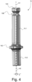
- the swivel member 15 is configured to exhibit first and second portions designated by reference numerals 15.1 and 15.2, respectively, which first and second portions 15.1, 15.2 extend along respective axes designated by references A1 and A2 respectively.
- the second portion 15.2 of the swivel member 15 is designed to be coupled to the relevant caster wheel 4', while the first portion 15.1 of the swivel member 15 is held by a holding member 12 that is secured to the second section of the support member 11.
- a shoulder portion 15C is furthermore preferably formed between the first and second portions 15.1, 15.2 to provide support against which the relevant upper portion of the fork element 16' can come in abutment.
- the holding member 12 preferably comprises a substantially cylindrical guiding aperture 12A extending along the first axis A1 and inside which the first portion 15.1 of the swivel member 15 is supported.
- the first and second portions 15.1, 15.2 of the swivel member 15 are preferably substantially cylindrical portions coaxial to the first and second axes A1, A2, respectively.
- the first portion 15.1 further exhibits a grooved section 15B designed to retain the swivel member 15 inside the guiding aperture 12A (see Figures 2D , 3 and 4 ).
- the holding member 12 is depicted in transparency to reveal the first portion 15.1 of the swivel member 15 held therein.
- the holding member 12 is preferably secured to the second section of the support member 11 by means of an adjustable retaining mechanism 11.3/11.4/14, which will be described in greater detail hereafter.
- the second section of the support member 11 advantageously exhibits first and second extensions 11.3, 11.4 forming an opening gap 112 between them, which opening gap 112 is dimensioned to receive the holding member 12.
- the holding member 12 is held and secured to the second section of the support member 11 by means of a pair of (upper and lower) retaining elements 14 that are provided in upper and lower portions of the extensions 11.3, 11.4, each provided with corresponding retaining apertures 14A, 14B.
- Corresponding retaining apertures 14C, 14D are likewise formed on the holding member 12 for cooperation with the upper and lower retaining elements 14.
- retaining elements 14 each include a bolt 14.1, a pair of washers 14.2, 14.3 and a nut 14.4 (see Figure 2D ), the holding member 12 being selectively clampable between the extensions 11.3, 11.4 by tightening the retaining elements 14. Conversely, tension can be released by loosening the retaining elements 14.
- retaining elements 14 advantageously fulfill two purposes, namely (i) securing the holding member 12 to the second section of the support member 11 and selectively allowing adjustment of the position of the holding member 12 with respect to the support member 11 to be carried out if need be (leading to a corresponding adjustment of the caster angle in the driving direction as discussed below) and (ii) clamping the swivel member 15 onto the holding member 12 and selectively allowing adjustment of the rotational position of the swivel member 15 with respect to the holding member 12 to be carried out if need be (leading to a corresponding adjustment of the camber of the caster wheel 4 as discussed below).
- the upper retaining element 14 fulfills yet another purpose, namely to interact with the aforementioned grooved section 15B on the first portion 15.1 of the swivel member 15 to retain the swivel member 15 inside the guiding aperture 12A.
- the second portion 15.2 of the swivel member 15 extends away from the first portion 15.1 along the second axis A2, which second axis A2 forms an angle ⁇ relative to the first axis A1.
- this angle ⁇ does not exceed 5°, and is preferably of the order of 2°.
- the holding member 12 and swivel member 15 are configured such that the first portion 15.1 of the swivel member 15 is supported by the holding member 12 to selectively allow rotation of the swivel member 15 relative to the holding member 12 about the first axis A1. Thanks to the particular configuration of the swivel member 15, rotation of the swivel member 15 about the first axis A1 will cause the second portion 15.2 to rotate along a conical trajectory coaxial with the first axis A1. This movement is exploited to carry out adjustment of the camber of the caster wheel 4' that is coupled to the second portion 15.2 of the swivel member 15.
- the holding member 12 is designed as a collet configured to selectively allow :
- the swivel member 15 is released to permit rotation of the swivel member 15 relative to the holding member 12 when adjustment of the camber of the associated caster wheel 4 is required. Once adjustment of the camber has been carried out, the swivel member 15 is clamped onto the holding member 12 to prevent any undesired rotation of the swivel member 15 relative to the holding member 12 under normal operating conditions.
- the holding member 12 comprises a longitudinal opening gap 12B formed along an axial length of the holding member 12 (see e.g. Figures 2B and 2D ), which longitudinal opening gap 12B is designed to selectively allow clamping or release of the swivel member 15 with respect to the holding member 12.
- clamping of the swivel member 15 onto the holding member 12 is achieved thanks to the aforementioned retaining mechanism 11.3/11.4/14, which also acts as clamping mechanism.
- the retaining elements 14 not only act as retaining elements in this example, but also as clamping elements to selectively clamp the swivel member 15 onto the holding member 12.
- the swivel member 15 is prevented from being able to rotate with respect to the holding member 12 by clamping using the retaining elements 14. Loosening the retaining elements 14 allows for the swivel member 15 to be selectively turned about the first axis A1 to carry out adjustments of the camber.
- the first portion 15.1 of the swivel member 15 preferably comprises a head portion 15A that is designed to allow manual rotation of the swivel member 15 about the first axis A1 by means of a tool, such as a screwdriver.
- the head portion 15A is accessible from an upper portion of the caster wheel support assembly 10 (see e.g. Figures 2A , 2C and 3 ).
- the camber of the caster wheel is adjustable in a continuous, stepless manner as a result of rotation of the swivel member 15 about the first axis A1, which is achieved, in the illustrated embodiment, thanks to the overall configuration of the swivel member 15 and holding member 12, which allows for the swivel member 15 to be turned to any desired angular position.
- the caster wheel support assembly 10 is secured, at the first section 10A, to the relevant frame member 20' by means of the support member 11.
- the corresponding first section of the support member 11 is advantageously provided with a clamping mechanism 11.5/11.6/13.
- each end of the first and second arms 11.1, 11.2 that is secured to the frame member 20' is designed as a clamping collar comprising first and second extensions 11.5, 11.6 separated by an opening gap 113 and a clamping element 13 (such as a bolt) that cooperates with both extensions 11.5, 11.6 to selectively allow tightening or loosening of the resulting clamping collar.
- the resulting mounting aperture 120 can accordingly be tightened or loosened around the relevant portion of the frame member 20'.
- the frame member 20' advantageously exhibits a non-circular cross-section where the caster wheel support assembly 10 is secured to the frame member 20', and each mounting aperture 120 exhibits a shape that substantially matches the non-circular cross-section of the frame member 20', thereby preventing any rotation of the support member 11 with respect to the frame member 20'.
- the frame member 20' and the support member 11 are configured such that the support member 11 is slidably adjustable along the frame member 20', namely by loosening the clamping elements 13, moving the support member 11 up or down along the frame member 20', and then tightening again the clamping elements 13 to secure the caster wheel support assembly 10 onto the desired portion of the frame member 20'.
- this adjustment does not in any way affect or compromise the adjustment of the camber or caster angle of the caster wheel arrangement.
- the frame member 20' is a hydroformed part, in particular a hydroformed part made of aluminum. Hydroforming is particularly advantageous in that this technique allows to shape the relevant frame member 20' to exhibit the desired non-circular cross-section.
- Figures 5A to 5C illustrate adjustment of the caster angle forward or rearward in the driving direction in the context of the aforementioned first embodiment of the invention.
- the holding member 12 is held on the second section 10B of the caster wheel support assembly 10, namely on the second section of the support member 11, by means of the retaining mechanism 11.3/11.4/14, which is designed to selectively allow adjustment of the position of the holding member 12 with respect to the support member 11 to be carried out if need be.
- FIGs 7A to 7F are illustrative of a caster wheel support assembly, designated by reference numeral 10*, in accordance with a second embodiment of the present invention.
- This caster wheel support assembly 10* likewise has a first section 10A* configured to be securable to a frame member 20* of a wheelchair and a second section 10B* configured to hold a swivel member 15, which swivel member 15 is designed in the same way as the swivel member 15 used in the first embodiment (see again Figure 4 ).
- the caster wheel support assembly 10* also comprises a holding member 12* configured to hold the first portion 15.1 of the swivel member 15, the head portion 15A thereof being visible in Figures 7A to 7C (see also Figure 7D ).
- the second portion 15.2 of the swivel member 15 (not visible in Figures 7A and 7B - see Figures 7C to 7F ) is likewise coupled to a caster wheel 4* by means of a fork element 16*, the upper end of which comes in abutment with the shoulder portion 15C of the swivel member 15.
- the holding member 12* itself is configured to be securable directly to the frame member 20*.
- the holding member 12* exhibits an extension 12.1* configured to be secured to the frame member 20* by means of an adequate securing mechanism comprising in the instant example a (first) retaining element 14* (not shown in Figures 7A and 7B ) cooperating with a corresponding retaining aperture 14A* provided in an upper portion of the holding member 12* and another retaining element 14** (likewise not shown in Figures 7A and 7B ) cooperating with a corresponding, arc-shaped retaining aperture 14C* provided in extension 12.1*.
- an adequate securing mechanism comprising in the instant example a (first) retaining element 14* (not shown in Figures 7A and 7B ) cooperating with a corresponding retaining aperture 14A* provided in an upper portion of the holding member 12* and another retaining element 14** (likewise not shown in Figures 7A and 7B ) cooperating with a corresponding, arc-shaped retaining aperture 14C* provided
- the caster wheel support assembly 10* is likewise configured to allow adjustment of an angle of inclination of the swivel member 15 forward or rearward in a driving direction, namely by securing the holding member 12* in such a way that a position with respect to the frame member 20* can be adjusted if need be (see Figures 7E and 7F ).
- Figures 7E and 7F illustrate adjustment of the caster angle forward or rearward in the driving direction in the context of the aforementioned second embodiment of the invention.
- the holding member 12* is held on the frame member 20* by means the (upper) retaining element 14* and retaining element 14** in such a way as to selectively allow adjustment of the position of the holding member 12* with respect to the frame member 20* to be carried out if need be.
- This is achieved by configuring the retaining aperture 14C* formed in extension 12.1* to exhibit an arc shape and exploiting the (upper) retaining aperture 14A* and associated retaining element 14* as a pivot axis about which the holding member 12* can pivot after having loosened the retaining elements 14*, 14** as schematically depicted.
- an angle of inclination of the swivel member 15 can be adjusted forward or rearward in a driving direction, leading to a corresponding adjustment of the caster angle.
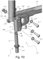
- retaining elements 14*, 14** each include a bolt 14.1*, resp. 14.1**, a pair of washers 14.2*, 14.3*, resp. 14.2**, 14.3**, and a nut 14.4* (see Figure 7D , the nut associated to bolt 14.1** being not visible in this illustration).
- Figure 7D further shows the presence of an additional adjustment element 14.5** provided in a corresponding retaining aperture 14D* that communicates with the retaining aperture 14C* where the retaining element 14** is provided.
- This additional adjustment element 14.5** is designed to interact with the retaining element 14** to define and adjust the desired caster angle.
- the holding member 12* is likewise designed as a collet configured to selectively allow:
- the holding member 12* to comprise a guiding aperture 12A* extending along the first axis A1 and inside which the first portion 15.1 of the swivel member 15 is supported, as well as a longitudinal opening gap 12B* formed along an axial length of the holding member 12* to selectively allow clamping or release of the swivel member 15 with respect to the holding member 12*, for instance by means of a pair of (upper and lower) retaining and clamping elements 14* cooperating with corresponding retaining apertures 14A*, 14B* provided in the holding member 12*.
- the upper retaining and clamping element 14* likewise cooperates with the grooved section 15B formed in the first portion 15.1 of the swivel member 15 to ensure that the swivel member is held inside the guiding aperture 12A* as long as the upper retaining and clamping element 14* remains in place.
- Adjustment of the camber is carried out in the same way as in the context of the first embodiment, namely by loosening the retaining and clamping elements 14*, turning the swivel member 15 by means of a tool, such as a screwdriver, to adjust the camber to the desired setting, and retightening the retaining and clamping elements 14* after the camber has been adjusted.
- the swivel member used in the context of the embodiments described above exhibits a substantially cylindrical first portion and is rotatable over 360°
- the embodiments disclosed herein show wheelchairs equipped with a pair of front caster wheels, the invention is generally applicable to any wheelchair comprising one or more caster wheel support assemblies provided at the front and/or rear end of the wheelchair.
Description
- The present invention generally relates to a caster wheel support assembly for a wheelchair and a wheelchair comprising the same.
- Caster wheel support assemblies are known as such in the art.
-
US Patent No. US 7,353,566 B2 and corresponding International (PCT) Publication No.WO 03/104028 A2 - Further examples of caster wheel support assemblies which allow for adjustment of the caster angle are disclosed in
European Patent Publications Nos. andEP 1 454 764 A1EP 1 872 761 A1WO 2012/131642 A1 ,US Patent No. US 7,520 ,518 B2 andGerman Utility Model No. DE 298 17 702 U1 . - Yet another example of a known caster wheel support assembly is commercially available on the market as a component of the Champion® and Champion® SK wheelchairs sold by company Küschall AG (www.kuschall.com), an illustration of which is reproduced in
Figures 1A to 1D hereof. Such a wheelchair and caster wheel support assembly are also disclosed in International (PCT)Publications Nos. WO 2013/093874 A1 ,WO 2014/057306 A1 andWO 2016/042444 A1 . -
Figure 1A is a photographic illustration of Küschall's Champion® SK wheelchair, which is generally designated byreference numeral 1. Thiswheelchair 1 comprises awheelchair frame 2 supporting aseat 5, a pair ofrear wheels 3 allowing manual wheeling of thewheelchair 1, and a pair offront caster wheels 4 that are coupled to a front end of thewheelchair frame 2. More specifically, thewheelchair frame 2 comprises a pair ofside frame members 20 provided on the left-hand and right-hand sides of thewheelchair 1, whichside frame members 20 consist here of essentially L-shaped tubular frame members having a circular cross-section. A casterwheel support assembly 6 is secured to a front end of eachframe member 20 to support the relevantfront caster wheels 4 as shown in greater detail inFigures 1B to 1D .Figure 1A further shows that the front end of thetubular frame members 20, above the location where the casterwheel support assemblies 6 are secured to theframe members 20, is configured to be foldable, a particularly advantageous feature of the Champion® SK wheelchair. -
Figure 1B is an enlarged view of the photographic illustration ofFigure 1A showing in greater detail one of the caster wheel support assemblies 6 (namely the one located on the right-hand side of the wheelchair 1) secured to the front end of the associatedframe member 20. As illustrated, the casterwheel support assembly 6 comprises asupport member 7 having a first section that is secured to theframe member 20 and a second section that is configured to hold aswivel member 8. Thisswivel member 8 is coupled to therelevant caster wheel 4 via afork element 16 that is freely rotatable about the axis of theswivel member 8. Reference numeral 9.1 designates a first pair of bolts that are used to clamp thesupport member 7 on therelevant frame member 20, while reference numeral 9.2 designates a second pair of bolts that are used to secure theswivel member 8 to thesupport member 7. - Two parameters are to be taken into consideration when adjusting the
caster wheels 4 with respect to therelevant frame members 20, namely the caster angle and camber angle (or simply camber). In essence, "caster angle" designates the angle formed by the caster wheel arrangement in the driving direction, while "camber (angle)" designates the angle formed by the caster wheel arrangement transversely to the driving direction. Ideally, caster angle and camber should be set to 0°, i.e. the axis of theswivel member 8 about which thefork element 16 is free to rotate should be vertical to ensure optimal behavior and performance. -
Figures 1C and1D schematically illustrate how caster angle and camber are adjusted with the known casterwheel support assembly 6 depicted inFigure 1B . - Referring to
Figure 1C which illustrates adjustment of the caster angle, thewheelchair 1 is first placed on a planar surface and thecaster wheel 4 is turned transversely to the driving direction (NB: by convention, it will be assumed in the following that the driving direction is a direction that coincides with the x-axis of a Cartesian coordinate system x-y-z as reproduced in the drawings). A 90° ruler (such as a triangular ruler) is then placed next to the side of thecaster wheel 4, as schematically shown inFigure 1C , to check if thecaster wheel 4 is perfectly vertical. If a gap exists between thecaster wheel 4 and the ruler (as indicated by reference A inFigure 1C ), which is indicative of the fact that adjustment of the caster angle is required, the bolts 9.2 are loosened to allow theswivel member 8 to be adjusted with respect to the support member 7 (as indicated by the double arrow inFigure 1C ). Adjustment of the position of theswivel member 8 relative to thesupport member 7 is carried out manually to ensure that thecaster wheel 4 is perfectly vertical and the gap with the ruler is eliminated, thereby correcting the caster angle accordingly. Once the adjustment is made, the bolts 9.2 are tightened again to secure theswivel member 8 onto thesupport member 7. - Referring to
Figure 1D which illustrates adjustment of the camber of thecaster wheel 4, thewheelchair 1 is likewise first placed on a planar surface and thecaster wheel 4 is turned in this case so as to be aligned with the driving direction. A 90° ruler is then placed next to the side of thecaster wheel 4, as schematically shown inFigure 1D , to similarly check if thecaster wheel 4 is perfectly vertical. If a gap exists between thecaster wheel 4 and the ruler (as indicated once again by reference A inFigure 1D ), which is indicative of the fact that adjustment of the camber is required, the bolts 9.1 are loosened in this case to allow thesupport member 7 to be adjusted (i.e. turned) with respect to the frame member 20 (as indicated by the double arrow inFigure 1D ). Adjustment of the position of thesupport member 7 relative to theframe member 20 is carried out manually to ensure that thecaster wheel 4 is perfectly vertical and the gap with the ruler is eliminated, thereby correcting the camber accordingly. Once the adjustment is made, the bolts 9.1 are tightened again to clamp thesupport member 7 onto theframe member 20. - A drawback with the aforementioned approach resides in that adjustment of the camber requires loosening of the bolts 9.1 and movement of the
entire support member 7 relative to theframe member 20, which may compromise vertical adjustment of the casterwheel support assembly 6 along theframe member 20, and vice versa. This adjustment may furthermore lead to undesired damage to thesupport member 7 and/orframe member 20 as a result of friction or dirt finding its way between the two components. The cross-section of the relevant portion of theframe member 20, where the casterwheel support assembly 6 is secured, is furthermore necessarily circular to allow thesupport member 7 to be turned relative to theframe member 20 during adjustment, as mentioned above in connection withFigure 1D , which also leads to potential adjustment inaccuracies. -
Japanese Patent Publication No. JP 2003-180758 A - There is therefore a need for an improved solution which facilitates adjustment of the caster wheel(s) of a wheelchair, especially adjustment of the camber of the caster wheel(s).
- A general aim of the invention is to provide such a caster wheel support assembly that is easy to adjust on a wheelchair.
- Yet another aim of the invention is to provide such a caster wheel support assembly that allows for a camber of the caster wheel to be adjusted if need be and in a simple manner.
- A further aim of the invention is to provide such a caster wheel support assembly which is of simple construction, is robust and cost-efficient to produce.
- Still another aim of the invention is to provide such a caster wheel support assembly which can be adjusted without causing undesired damage to the wheelchair frame onto which the caster wheel support assembly is secured.
- These aims are achieved thanks to the solutions defined in the claims.
- In accordance with the invention, there is provided a caster wheel support assembly for a wheelchair as defined in
claim 1, namely a caster wheel support assembly having a first section configured to be securable to a frame member of the wheelchair and a second section holding a swivel member coupled to a caster wheel. According to the invention, the caster wheel support assembly comprises a holding member designed as a collet configured to hold a first portion of the swivel member, which first portion extends along a first axis. A second portion of the swivel member, which is coupled to the caster wheel, extends away from the first portion along a second axis, which second axis forms an angle relative to the first axis. The holding member and swivel member are configured such that the first portion of the swivel member is supported by the holding member to selectively allow rotation of the swivel member relative to the holding member about the first axis and thereby cause adjustment of a camber of the caster wheel. - The collet is configured to selectively allow :
- clamping of the swivel member onto the holding member, thereby preventing rotation of the swivel member relative to the holding member; and
- release of the swivel member with respect to the holding member, thereby permitting rotation of the swivel member relative to the holding member.
- In this context, the holding member may advantageously comprise a longitudinal opening gap formed along an axial length of the holding member, which longitudinal opening gap is designed to selectively allow clamping or release of the swivel member with respect to the holding member.
- In accordance with a preferred embodiment of the invention, the first portion of the swivel member comprises a head portion that is designed to allow manual rotation of the swivel member about the first axis by means of a tool.
- Preferably, the camber of the caster wheel is adjustable in a continuous, stepless manner as a result of rotation of the swivel member about the first axis.
- According to an advantageous embodiment of the invention, the angle formed between the first and second axes does not exceed 5°, and is preferably of the order of 2°.
- By way of preference, the holding member comprises a guiding aperture extending along the first axis and inside which the first portion of the swivel member is supported. In this context, the first and second portions of the swivel member may in particular be substantially cylindrical portions coaxial to the first and second axes, respectively, and the first portion of the swivel member may advantageously exhibit a grooved section designed to retain the swivel member inside the guiding aperture, the caster wheel support assembly further comprising a retaining element secured to the holding member, which retaining element cooperates with the grooved section on the first portion of the swivel member. Moreover, this retaining element can also advantageously act as clamping element to selectively clamp the swivel member onto the holding member and prevent rotation of the swivel member relative to the holding member.
- According to yet another embodiment of the invention, the caster wheel support assembly may be configured to allow adjustment of an angle of inclination of the swivel member forward or rearward in a driving direction.
- In accordance with an advantageous variant of the invention, the caster wheel support assembly may further comprise a support member with first and second sections acting respectively as the first and second sections of the caster wheel support assembly, the holding member being secured to the second section of the support member. In this context, the first section of the support member preferably comprises first and second arms each configured to be securable to the frame member.
- In accordance with another variant of the invention, the holding member itself is configured to be securable directly to the frame member.
- Also claimed is a wheelchair comprising at least one caster wheel support assembly in accordance with the invention, which caster wheel support assembly is secured to a frame member of the wheelchair.
- In accordance with a particularly preferred embodiment of the aforementioned wheelchair, the caster wheel support assembly is a caster wheel support assembly comprising the aforementioned support member, and the frame member exhibits a non-circular cross-section where the caster wheel support assembly is secured to the frame member, the first section of the support member being provided with at least one mounting aperture the shape of which substantially matches the non-circular cross-section of the frame member, preventing any rotation of the support member with respect to the frame member. In this context, the frame member and the support member of the caster wheel support assembly may further be configured such that the support member is slidably adjustable along the frame member.
- Furthermore, the frame member may advantageously be a hydroformed part, preferably made of aluminum.
- Further advantageous embodiments of the invention are discussed below.
- Other features and advantages of the present invention will appear more clearly from reading the following detailed description of embodiments of the invention which are presented solely by way of non-restrictive examples and illustrated by the attached drawings in which:
-
Figure 1A is a photographic illustration of a known commercially-available wheelchair, namely the Champion® SK wheelchair as sold by company Küschall AG ; -
Figure 1B is an enlarged view of the photographic illustration ofFigure 1A showing a known caster wheel support assembly secured on a frame member at a front end of the wheelchair frame ; -
Figure 1C is a schematic drawing of the known caster wheel support assembly ofFigure 1B , mounted on the relevant frame member, as seen from the side, and illustrating adjustment of the angle of the caster wheel relative to a driving direction (or "caster angle") ; -
Figure 1D is a schematic drawing of the known caster wheel support assembly ofFigure 1B , mounted on the relevant frame member, as seen from the front, and illustrating adjustment of the camber of the caster wheel relative to the driving direction (also referred to as "drift angle") ; -
Figure 2A is a perspective view of a caster wheel support assembly in accordance with a first embodiment of the present invention ; -
Figure 2B is a bottom view of the caster wheel support assembly ofFigure 2A ; -
Figure 2C is a rear view of the caster wheel support assembly ofFigure 2A ; -
Figure 2D is an exploded perspective view of the caster wheel support assembly ofFigure 2A ; -
Figure 3 is a partial perspective view of the caster wheel support assembly ofFigure 2A as seen from above ; -
Figure 4 is a side view of a swivel member of the caster wheel support assembly ofFigure 2A ; -
Figure 5A is a side view of the caster wheel support assembly ofFigure 2A showing the swivel member in a first configuration with respect to the frame member onto which the caster wheel support assembly is mounted ; -
Figure 5B is a partial top view of the caster wheel support assembly ofFigure 5A showing an upper portion of the swivel member; -
Figure 5C is another side view of the caster wheel support assembly ofFigure 2A showing the swivel member in a second configuration with respect to the frame member onto which the caster wheel support assembly is mounted ; -
Figure 6 is a photographic illustration of the caster wheel support assembly ofFigure 2A as secured on a relevant portion of a frame member of a wheelchair; -
Figures 7A and7B are perspective views taken from different angles of a caster wheel support assembly in accordance with a second embodiment of the present invention ; -
Figure 7C is another perspective view of the caster wheel support assembly ofFigures 7A and7B depicted without the associated caster wheel arrangement; -
Figure 7D is an exploded perspective view of the caster wheel support assembly ofFigure 7C ; -
Figure 7E is a side view of the caster wheel support assembly ofFigure 7C showing the swivel member in a first configuration with respect to the frame member onto which the caster wheel support assembly is mounted ; and -
Figure 7F is another side view of the caster wheel support assembly ofFigure 7C showing the swivel member in a second configuration with respect to the frame member onto which the caster wheel support assembly is mounted. - The present invention will be described in relation to various illustrative embodiments.
- As described herein, when two or more parts or components are described as being connected, secured or coupled to one another, they can be so connected, secured or coupled directly to each other or through one or more intermediary parts.
- The invention will be described in relation to various embodiments of a caster wheel support assembly for attachment to a front end of a wheelchair frame, in a manner similar to the known caster wheel support assembly depicted in
Figures 1A to 1D . As a matter of fact, the caster wheel support assembly of the invention is retrofittable on existing wheelchairs, including but not limited to thewheelchair 1 depicted inFigure 1A . It is worth pointing out that the invention is generally applicable to any wheelchair comprising at least one caster wheel support assembly, be it at a front end and/or rear end of the wheelchair. -
Figure 2A is a perspective view of a caster wheel support assembly in accordance with a first embodiment of the present invention, which caster wheel support assembly is generally designated byreference numeral 10. The casterwheel support assembly 10 generally has afirst section 10A that is configured to be securable to a frame member of a wheelchair and asecond section 10B that is configured to hold aswivel member 15 coupled to a caster wheel (not shown inFigure 2A ). Such a caster wheel, designated by reference numeral 4', is depicted in the photographic illustration ofFigure 6 and can in particular be coupled to theswivel member 15 by means of a fork element 16', in a manner similar to the known casterwheel support assembly 6 ofFigures 1A to 1D . - A portion of a frame member, designated by reference numeral 20', secured to the
first section 10A of the casterwheel support assembly 10, is schematically depicted in dashed lines inFigure 2A for the sake of illustration and explanation. In the present instance, the casterwheel support assembly 10 is illustrated in a configuration suitable for mounting on the left-hand side of a wheelchair frame (see alsoFigure 6 ). It is to be understood that a similar casterwheel support assembly 10 exhibiting a mirrored configuration would be mounted on the right-hand side of the wheelchair frame. The overall shape and configuration of the casterwheel support assembly 10 as depicted inFigure 2A is not however limitative and may vary depending on the application and/or on design considerations. - A Cartesian coordinate system x-y-z is also reproduced in
Figure 2A for the sake of identifying the relevant orientation in which the casterwheel support assembly 10 is mounted. As already mentioned above, it will be assumed that the x-axis coincides with the relevant driving direction and that the y-axis designates a lateral direction, transversely to the driving direction, while the z-axis designates a direction perpendicular to the plane formed by the x-axis and y-axis. - In a manner similar to the known caster
wheel support assembly 6 depicted inFigures 1A to 1D , the casterwheel support assembly 10 according to this first embodiment of the invention comprises asupport member 11 having a first section acting as the aforementionedfirst section 10A of the casterwheel support assembly 10, which first section is accordingly configured to be securable to the frame member 20'. Thesupport member 11 further has a second section acting as the aforementionedsecond section 10B of the casterwheel support assembly 10, which second section is configured to hold theswivel member 15. - The first section of the
support member 11 may in particular comprise first and second arms 11.1, 11.2 each configured to be securable to the relevant frame member 20', each arm 11.1, 11.2 being provided with a corresponding mountingaperture 120, the shape of which substantially matches the cross-section of the frame member 20'. In the present instance, it may be appreciated that the cross-section of the frame member 20' is advantageously non-circular (see alsoFigures 2B to 2D ). - The configuration of the caster
wheel support assembly 10 and relevant components thereof are further illustrated inFigures 2B to 2D ,3 and4 . More precisely, theswivel member 15 is configured to exhibit first and second portions designated by reference numerals 15.1 and 15.2, respectively, which first and second portions 15.1, 15.2 extend along respective axes designated by references A1 and A2 respectively. The second portion 15.2 of theswivel member 15 is designed to be coupled to the relevant caster wheel 4', while the first portion 15.1 of theswivel member 15 is held by a holdingmember 12 that is secured to the second section of thesupport member 11. Ashoulder portion 15C is furthermore preferably formed between the first and second portions 15.1, 15.2 to provide support against which the relevant upper portion of the fork element 16' can come in abutment. - In the illustrated embodiment, the holding
member 12 preferably comprises a substantiallycylindrical guiding aperture 12A extending along the first axis A1 and inside which the first portion 15.1 of theswivel member 15 is supported. As illustrated, the first and second portions 15.1, 15.2 of theswivel member 15 are preferably substantially cylindrical portions coaxial to the first and second axes A1, A2, respectively. Furthermore, in the illustrated example, the first portion 15.1 further exhibits agrooved section 15B designed to retain theswivel member 15 inside the guidingaperture 12A (seeFigures 2D ,3 and4 ). InFigure 3 , the holdingmember 12 is depicted in transparency to reveal the first portion 15.1 of theswivel member 15 held therein. - The holding
member 12 is preferably secured to the second section of thesupport member 11 by means of an adjustable retaining mechanism 11.3/11.4/14, which will be described in greater detail hereafter. In the illustrated example, the second section of thesupport member 11 advantageously exhibits first and second extensions 11.3, 11.4 forming anopening gap 112 between them, whichopening gap 112 is dimensioned to receive the holdingmember 12. In the illustrated example, the holdingmember 12 is held and secured to the second section of thesupport member 11 by means of a pair of (upper and lower) retainingelements 14 that are provided in upper and lower portions of the extensions 11.3, 11.4, each provided withcorresponding retaining apertures apertures member 12 for cooperation with the upper andlower retaining elements 14. - In the illustrated example, retaining
elements 14 each include a bolt 14.1, a pair of washers 14.2, 14.3 and a nut 14.4 (seeFigure 2D ), the holdingmember 12 being selectively clampable between the extensions 11.3, 11.4 by tightening the retainingelements 14. Conversely, tension can be released by loosening the retainingelements 14. In the illustrated embodiment, retainingelements 14 advantageously fulfill two purposes, namely (i) securing the holdingmember 12 to the second section of thesupport member 11 and selectively allowing adjustment of the position of the holdingmember 12 with respect to thesupport member 11 to be carried out if need be (leading to a corresponding adjustment of the caster angle in the driving direction as discussed below) and (ii) clamping theswivel member 15 onto the holdingmember 12 and selectively allowing adjustment of the rotational position of theswivel member 15 with respect to the holdingmember 12 to be carried out if need be (leading to a corresponding adjustment of the camber of thecaster wheel 4 as discussed below). - It will further be appreciated that, in the illustrated embodiment, the upper retaining
element 14 fulfills yet another purpose, namely to interact with the aforementionedgrooved section 15B on the first portion 15.1 of theswivel member 15 to retain theswivel member 15 inside the guidingaperture 12A. - As this is more clearly apparent from looking at the illustrations of
Figures 2C and4 , the second portion 15.2 of theswivel member 15 extends away from the first portion 15.1 along the second axis A2, which second axis A2 forms an angle α relative to the first axis A1. By way of preference, this angle α does not exceed 5°, and is preferably of the order of 2°. - According to the invention, the holding
member 12 andswivel member 15 are configured such that the first portion 15.1 of theswivel member 15 is supported by the holdingmember 12 to selectively allow rotation of theswivel member 15 relative to the holdingmember 12 about the first axis A1. Thanks to the particular configuration of theswivel member 15, rotation of theswivel member 15 about the first axis A1 will cause the second portion 15.2 to rotate along a conical trajectory coaxial with the first axis A1. This movement is exploited to carry out adjustment of the camber of the caster wheel 4' that is coupled to the second portion 15.2 of theswivel member 15. - In accordance with the invention, as depicted e.g. in
Figures 2A to 2D ,3 and4 , the holdingmember 12 is designed as a collet configured to selectively allow : - (i) clamping of the
swivel member 15 onto the holdingmember 12, thereby preventing rotation of theswivel member 15 relative to the holdingmember 12; and - (ii) release of the
swivel member 15 with respect to the holdingmember 12, thereby permitting rotation of theswivel member 15 relative to the holdingmember 12. - It will therefore be understood that the
swivel member 15 is released to permit rotation of theswivel member 15 relative to the holdingmember 12 when adjustment of the camber of the associatedcaster wheel 4 is required. Once adjustment of the camber has been carried out, theswivel member 15 is clamped onto the holdingmember 12 to prevent any undesired rotation of theswivel member 15 relative to the holdingmember 12 under normal operating conditions. - Clamping of the
swivel member 15 onto the holdingmember 12 can be achieved in various ways. By way of preference, the holdingmember 12 comprises alongitudinal opening gap 12B formed along an axial length of the holding member 12 (see e.g.Figures 2B and2D ), whichlongitudinal opening gap 12B is designed to selectively allow clamping or release of theswivel member 15 with respect to the holdingmember 12. In the illustrated example, clamping of theswivel member 15 onto the holdingmember 12 is achieved thanks to the aforementioned retaining mechanism 11.3/11.4/14, which also acts as clamping mechanism. More precisely, the retainingelements 14 not only act as retaining elements in this example, but also as clamping elements to selectively clamp theswivel member 15 onto the holdingmember 12. - Under normal operating conditions, the
swivel member 15 is prevented from being able to rotate with respect to the holdingmember 12 by clamping using the retainingelements 14. Loosening the retainingelements 14 allows for theswivel member 15 to be selectively turned about the first axis A1 to carry out adjustments of the camber. In order to facilitate such adjustments, the first portion 15.1 of theswivel member 15 preferably comprises ahead portion 15A that is designed to allow manual rotation of theswivel member 15 about the first axis A1 by means of a tool, such as a screwdriver. In the illustrated embodiment, thehead portion 15A is accessible from an upper portion of the caster wheel support assembly 10 (see e.g.Figures 2A ,2C and3 ). - By way of preference, the camber of the caster wheel is adjustable in a continuous, stepless manner as a result of rotation of the
swivel member 15 about the first axis A1, which is achieved, in the illustrated embodiment, thanks to the overall configuration of theswivel member 15 and holdingmember 12, which allows for theswivel member 15 to be turned to any desired angular position. - In the context of the aforementioned first embodiment, the caster
wheel support assembly 10 is secured, at thefirst section 10A, to the relevant frame member 20' by means of thesupport member 11. To this end, the corresponding first section of thesupport member 11 is advantageously provided with a clamping mechanism 11.5/11.6/13. More precisely, each end of the first and second arms 11.1, 11.2 that is secured to the frame member 20' is designed as a clamping collar comprising first and second extensions 11.5, 11.6 separated by anopening gap 113 and a clamping element 13 (such as a bolt) that cooperates with both extensions 11.5, 11.6 to selectively allow tightening or loosening of the resulting clamping collar. The resulting mountingaperture 120 can accordingly be tightened or loosened around the relevant portion of the frame member 20'. - As mentioned above, the frame member 20' advantageously exhibits a non-circular cross-section where the caster
wheel support assembly 10 is secured to the frame member 20', and each mountingaperture 120 exhibits a shape that substantially matches the non-circular cross-section of the frame member 20', thereby preventing any rotation of thesupport member 11 with respect to the frame member 20'. Moreover, according to this first embodiment of the invention, the frame member 20' and thesupport member 11 are configured such that thesupport member 11 is slidably adjustable along the frame member 20', namely by loosening the clampingelements 13, moving thesupport member 11 up or down along the frame member 20', and then tightening again the clampingelements 13 to secure the casterwheel support assembly 10 onto the desired portion of the frame member 20'. One will appreciate that this adjustment does not in any way affect or compromise the adjustment of the camber or caster angle of the caster wheel arrangement. - By way of preference, the frame member 20' is a hydroformed part, in particular a hydroformed part made of aluminum. Hydroforming is particularly advantageous in that this technique allows to shape the relevant frame member 20' to exhibit the desired non-circular cross-section.
-
Figures 5A to 5C illustrate adjustment of the caster angle forward or rearward in the driving direction in the context of the aforementioned first embodiment of the invention. As already mentioned above, the holdingmember 12 is held on thesecond section 10B of the casterwheel support assembly 10, namely on the second section of thesupport member 11, by means of the retaining mechanism 11.3/11.4/14, which is designed to selectively allow adjustment of the position of the holdingmember 12 with respect to thesupport member 11 to be carried out if need be. This can be achieved by configuring theupper retaining apertures 14A formed in extensions 11.3, 11.4 to exhibit an arc shape and exploiting thelower retaining apertures 14B and associated lower retainingelement 14 as a pivot axis about which the holdingmember 12 can pivot after having loosened the retainingelements 14 as schematically depicted. As a result, an angle of inclination of theswivel member 15 can be adjusted forward or rearward in a driving direction, leading to a corresponding adjustment of the caster angle. -
Figures 7A to 7F are illustrative of a caster wheel support assembly, designated byreference numeral 10*, in accordance with a second embodiment of the present invention. This casterwheel support assembly 10* likewise has afirst section 10A* configured to be securable to aframe member 20* of a wheelchair and asecond section 10B* configured to hold aswivel member 15, which swivelmember 15 is designed in the same way as theswivel member 15 used in the first embodiment (see againFigure 4 ). The casterwheel support assembly 10* also comprises a holdingmember 12* configured to hold the first portion 15.1 of theswivel member 15, thehead portion 15A thereof being visible inFigures 7A to 7C (see alsoFigure 7D ). The second portion 15.2 of the swivel member 15 (not visible inFigures 7A and7B - seeFigures 7C to 7F ) is likewise coupled to acaster wheel 4* by means of afork element 16*, the upper end of which comes in abutment with theshoulder portion 15C of theswivel member 15. - It may be appreciated that no support member is provided in this second embodiment. Rather, the holding
member 12* itself is configured to be securable directly to theframe member 20*. To this end, according to this second embodiment, the holdingmember 12* exhibits an extension 12.1* configured to be secured to theframe member 20* by means of an adequate securing mechanism comprising in the instant example a (first) retainingelement 14* (not shown inFigures 7A and7B ) cooperating with acorresponding retaining aperture 14A* provided in an upper portion of the holdingmember 12* and another retainingelement 14** (likewise not shown inFigures 7A and7B ) cooperating with a corresponding, arc-shapedretaining aperture 14C* provided in extension 12.1*. The casterwheel support assembly 10* is likewise configured to allow adjustment of an angle of inclination of theswivel member 15 forward or rearward in a driving direction, namely by securing the holdingmember 12* in such a way that a position with respect to theframe member 20* can be adjusted if need be (seeFigures 7E and7F ). - More precisely,
Figures 7E and7F illustrate adjustment of the caster angle forward or rearward in the driving direction in the context of the aforementioned second embodiment of the invention. The holdingmember 12* is held on theframe member 20* by means the (upper) retainingelement 14* and retainingelement 14** in such a way as to selectively allow adjustment of the position of the holdingmember 12* with respect to theframe member 20* to be carried out if need be. This is achieved by configuring the retainingaperture 14C* formed in extension 12.1* to exhibit an arc shape and exploiting the (upper) retainingaperture 14A* and associated retainingelement 14* as a pivot axis about which the holdingmember 12* can pivot after having loosened the retainingelements 14*, 14** as schematically depicted. As a result, an angle of inclination of theswivel member 15 can be adjusted forward or rearward in a driving direction, leading to a corresponding adjustment of the caster angle. - In the illustrated example, retaining
elements 14*, 14** each include a bolt 14.1*, resp. 14.1**, a pair of washers 14.2*, 14.3*, resp. 14.2**, 14.3**, and a nut 14.4* (seeFigure 7D , the nut associated to bolt 14.1** being not visible in this illustration).Figure 7D further shows the presence of an additional adjustment element 14.5** provided in acorresponding retaining aperture 14D* that communicates with the retainingaperture 14C* where the retainingelement 14** is provided. This additional adjustment element 14.5** is designed to interact with the retainingelement 14** to define and adjust the desired caster angle. - The holding
member 12* is likewise designed as a collet configured to selectively allow: - (i) clamping of the
swivel member 15 onto the holdingmember 12*, thereby preventing rotation of theswivel member 15 relative to the holdingmember 12*; and - (ii) release of the
swivel member 15 with respect to the holdingmember 12*, thereby permitting rotation of theswivel member 15 relative to the holdingmember 12*. - This is similarly achieved by designing the holding
member 12* to comprise a guidingaperture 12A* extending along the first axis A1 and inside which the first portion 15.1 of theswivel member 15 is supported, as well as alongitudinal opening gap 12B* formed along an axial length of the holdingmember 12* to selectively allow clamping or release of theswivel member 15 with respect to the holdingmember 12*, for instance by means of a pair of (upper and lower) retaining and clampingelements 14* cooperating with corresponding retainingapertures 14A*, 14B* provided in the holdingmember 12*. It shall be understood that the upper retaining and clampingelement 14* likewise cooperates with thegrooved section 15B formed in the first portion 15.1 of theswivel member 15 to ensure that the swivel member is held inside the guidingaperture 12A* as long as the upper retaining and clampingelement 14* remains in place. - Adjustment of the camber is carried out in the same way as in the context of the first embodiment, namely by loosening the retaining and clamping
elements 14*, turning theswivel member 15 by means of a tool, such as a screwdriver, to adjust the camber to the desired setting, and retightening the retaining and clampingelements 14* after the camber has been adjusted. - Various modifications and/or improvements may be made to the above-described embodiments without departing from the scope of the invention as defined by the annexed claims. For instance, selective clamping or release of the swivel member with respect to the holding member could be carried out in different ways than by tightening or loosening bolts. Any suitable releasable collet could in essence be used.
- In addition, while the swivel member used in the context of the embodiments described above exhibits a substantially cylindrical first portion and is rotatable over 360°, one could alternatively design the first portion of the swivel member to permit rotation only within a defined angular sector. As a matter of fact, it is sufficient for the camber adjustment to be adjustable over the complete range of e.g. +/- 2° to design the swivel member so as to be rotatable over an angular sector of 180° or more.
- Furthermore, although the embodiments disclosed herein show wheelchairs equipped with a pair of front caster wheels, the invention is generally applicable to any wheelchair comprising one or more caster wheel support assemblies provided at the front and/or rear end of the wheelchair.
-
- 1
- wheelchair
- 2
- wheelchair frame
- 3
- rear wheels
- 4
- front caster wheel(s)
- 4'
- front caster wheel (first embodiment)
- 4*
- front caster wheel (second embodiment)
- 5
- wheelchair seat
- 6
- caster wheel support assembly (prior art)
- 7
- support member of caster
wheel support assembly 6 - 8
- swivel member of caster
wheel support assembly 6 / coupled tocaster wheel 4 - 9.1
- pair of clamping elements (e.g. bolts) for securing (i.e. clamping)
support member 7 to framemember 20 - 9.2
- pair of retaining elements (e.g. bolts) for securing
swivel member 8 to supportmember 7 - 10
- caster wheel support assembly (first embodiment of invention)
- 10A
- first section of caster
wheel support assembly 10 configured to be securable to framemember 20 - 10B
- second section of caster
wheel support assembly 10 configured to holdswivel member 15 - 10*
- caster wheel support assembly (second embodiment of invention)
- 10A*
- first section of caster
wheel support assembly 10* configured to be securable to framemember 20* - 1 0B*
- second section of caster
wheel support assembly 10* configured to holdswivel member 15 - 11
- support member of caster
wheel support assembly 10 - 11.1
- (first / upper) arm of
support member 11 configured to be secured to framemember 20 - 11.2
- (second / lower) arm of
support member 11 configured to be secured to framemember 20 - 11.3
- (first / exterior) extension on second section of
support member 11 for securing holding member 12 (part of adjustable retaining mechanism 11.3/11.4/14) - 11.4
- (second / interior) extension on second section of
support member 11 for securing holding member 12 (part of adjustable retaining mechanism 11.3/11.4/14) - 11.5
- (first) extension on first and second arms 11.1, 11.2 for clamping caster
wheel support assembly 10 along a portion of frame member 20' (part of clamping mechanism 11.5/11.6/13) - 11.6
- (second) extension on first and second arms 11.1, 11.2 for clamping caster
wheel support assembly 10 along a portion of frame member 20' (part of clamping mechanism 11.5/11.6/13) - 12
- holding member secured to second section of
support member 11 and holding swivel member 15 (first embodiment) - 12A
- guiding aperture formed in holding
member 12 and extending along first axis A1 - 12B
- opening gap formed along the axial length of holding
member 12 - 12*
- holding member secured to frame
member 20* and holding swivel member 15 (second embodiment) - 12A*
- guiding aperture formed in holding
member 12* and extending along first axis A1 - 12B*
- opening gap formed along the axial length of holding
member 12* - 12.1*
- extension of holding
member 12* for attachment to framemember 20* - 13
- pair of (upper and lower) clamping elements (e.g. bolt) cooperating with first and second extension 11.5, 11.6 on first and second arms 11.1, 11.2 (part of clamping mechanism 11.5/11.6/13)
- 14
- pair of (upper and lower) retaining elements for securing holding
member 12 to second section of support member 11 (part of adjustable retaining mechanism 11.3/11.4/14) / also act as retaining and clamping elements for retaining and clampingswivel member 15 onto holdingmember 12 - 14.1
- bolt
- 14.2
- washer
- 14.3
- washer
- 14.4
- nut
- 14A
- arc-shaped retaining aperture provided in upper portion of extensions 11.3, 11.4 and designed to cooperate with upper retaining
element 14 - 14B
- retaining aperture provided in lower portion of extensions 11.3, 11.4 and designed to cooperate with
lower retaining element 14 - 14C
- retaining aperture provided in upper portion of holding
member 12 and designed to cooperate with upper retainingelement 14 - 14D
- retaining aperture provided in lower portion of holding
member 12 and designed to cooperate withlower retaining element 14 - 14*
- pair of (upper and lower) retaining and clamping elements for retaining and clamping
swivel member 15 onto holdingmember 12* - 14.1*
- bolt
- 14.2*
- washer
- 14.3*
- washer
- 14.4*
- nut
- 14**
- retaining element for retaining holding
member 12* ontoframe member 20* - 14.1**
- bolt
- 14.2**
- washer
- 14.3**
- washer
- 14.5**
- additional adjustment element
- 14A*
- retaining aperture provided in upper portion of holding
member 12* and designed to cooperate with upper retainingelement 14* - 14B*
- retaining aperture provided in lower portion of holding
member 12* and designed to cooperate withlower retaining element 14* - 14C*
- arc-shaped retaining aperture provided in extension 12.1* of holding
member 12* and designed to cooperate with retainingelement 14** - 14D*
- retaining aperture provided in extension 12.1* and communicating with arc-shaped retaining aperture for accommodating additional adjustment element 14.5**
- 15
- swivel member of caster
wheel support assembly 10 / coupled tocaster wheel 4', 4* - 15.1
- first portion of
swivel member 15 extending along first axis A1 / supported by holdingmember - 15.2
- second portion of
swivel member 15 extending along second axis A2 / coupled tocaster wheel 4', 4* / substantially cylindrical portion coaxial to second axis A2 - 15A
- head portion of
swivel member 15 designed to allow manual rotation of theswivel member 15 about first axis A1 by means of a tool (e.g. screwdriver) - 15B
- grooved section formed on first portion 15.1 of swivel member 15 (e.g. at an upper end of first portion 15.1) and designed to retain
swivel member 15 inside guidingaperture 12A / cooperates with e.g. upper retainingelement - 15C
- shoulder portion of
swivel member 15 located between first and second portions 15.1, 15.2 - 16
- fork element carrying caster wheel 4 (prior art)
- 16'
- fork element carrying caster wheel 4' (first embodiment)
- 16*
- fork element carrying
caster wheel 4* (second embodiment) - 20
- frame member / left-hand side and right-hand side frame members of wheelchair frame 2 (prior art)
- 20'
- frame member (first embodiment)
- 20*
- frame member (second embodiment)
- 112
- opening gap formed between first and second extensions 11.3, 11.4 and dimensioned to receive holding member 12 (first embodiment)
- 113
- opening gap formed between first and second extensions 11.5, 11.6 and dimensioned to allow clamping of caster
wheel support assembly 10 on frame member 20' (first embodiment) - 120
- pair of mounting apertures provided on
first section 10A of casterwheel support assembly 10 the shape of which substantially matches non-circular cross-section of frame member 20' (first embodiment) - A1
- first axis of
swivel member 15 - A2
- second axis of
swivel member 15 - α
- angle formed between first and second axes A1, A2
- x/y/z
- Cartesian coordinate system
Claims (15)
- A caster wheel support assembly (10; 10*) for a wheelchair (1), the caster wheel support assembly (10; 10*) having a first section (10A; 10A*) configured to be securable to a frame member (20'; 20*) of the wheelchair (1) and a second section (10B; 10B*) holding a swivel member (15) coupled to a caster wheel (4'; 4*),characterized in that the caster wheel support assembly (10; 10*) comprises a holding member (12; 12*) designed as a collet configured to hold a first portion (15.1) of the swivel member (15), which first portion (15.1) extends along a first axis (A1),in that a second portion (15.2) of the swivel member (15), which is coupled to the caster wheel (4'; 4*), extends away from the first portion (15.1) along a second axis (A2), which second axis (A2) forms an angle (α) relative to the first axis (A1),in that the holding member (12; 12*) and swivel member (15) are configured such that the first portion (15.1) of the swivel member (15) is supported by the holding member (12; 12*) to selectively allow rotation of the swivel member (15) relative to the holding member (12; 12*) about the first axis (A1) and thereby cause adjustment of a camber of the caster wheel (4'; 4*),and in that the collet is configured to selectively allow:- clamping of the swivel member (15) onto the holding member (12; 12*), thereby preventing rotation of the swivel member (15) relative to the holding member (12; 12*); and- release of the swivel member (15) with respect to the holding member (12; 12*), thereby permitting rotation of the swivel member (15) relative to the holding member (12; 12*).
- The caster wheel support assembly (10; 10*) according to claim 1, wherein the holding member (12; 12*) comprises a longitudinal opening gap (12B; 12B*) formed along an axial length of the holding member (12; 12*), which longitudinal opening gap (12B; 12B*) is designed to selectively allow clamping or release of the swivel member (15) with respect to the holding member (12; 12*).
- The caster wheel support assembly (10; 10*) according to claim 1 or 2, wherein the first portion (15.1) of the swivel member (15) comprises a head portion (15A) that is designed to allow manual rotation of the swivel member (15) about the first axis (A1) by means of a tool.
- The caster wheel support assembly (10; 10*) according to any one of the preceding claims, wherein the camber of the caster wheel (4', 4*) is adjustable in a continuous, stepless manner as a result of rotation of the swivel member (15) about the first axis (A1).
- The caster wheel support assembly (10; 10*) according to any one of the preceding claims, wherein the angle (α) formed between the first and second axes (A1, A2) does not exceed 5°, and is preferably of the order of 2°.
- The caster wheel support assembly (10; 10*) according to any one of the preceding claims, wherein the holding member (12; 12*) comprises a guiding aperture (12A; 12A*) extending along the first axis (A1) and inside which the first portion (15.1) of the swivel member (15) is supported.
- The caster wheel support assembly (10; 10*) according to claim 6, wherein the first and second portions (15.1, 15.2) of the swivel member (15) are substantially cylindrical portions coaxial to the first and second axes (A1, A2), respectively,wherein the first portion (15.1) of the swivel member (15) exhibits a grooved section (15B) designed to retain the swivel member (15) inside the guiding aperture (12A; 12A*),and wherein the caster wheel support assembly (10; 10*) further comprises a retaining element (14; 14*) secured to the holding member (12; 12*), which retaining element (14; 14*) cooperates with the grooved section (15B) on the first portion (15.1) of the swivel member (15).
- The caster wheel support assembly (10; 10*) according to claim 7, wherein the retaining element (14; 14*) also acts as clamping element to selectively clamp the swivel member (15) onto the holding member (12; 12*) and prevent rotation of the swivel member (15) relative to the holding member (12; 12*).
- The caster wheel support assembly (10; 10*) according to any one of the preceding claims, wherein the caster wheel support assembly (10; 10*) is configured to allow adjustment of an angle of inclination of the swivel member (15) forward or rearward in a driving direction.
- The caster wheel support assembly (10) according to any one of the preceding claims, wherein the caster wheel support assembly (10) further comprises a support member (11) having first and second sections acting respectively as the first and second sections (10A, 10B) of the caster wheel support assembly (10), the holding member (12) being secured to the second section of the support member (11),
and wherein the first section of the support member (11) preferably comprises first and second arms (11.1, 11.2) each configured to be securable to the frame member (20'). - The caster wheel support assembly (10*) according to any one of claims 1 to 9, wherein the holding member (12*) itself is configured to be securable directly to the frame member (20*).
- A wheelchair (1) comprising at least one caster wheel support assembly (10; 10*) according to any one of the preceding claims secured to a frame member (20'; 20*) of the wheelchair (1).
- A wheelchair (1) comprising at least one caster wheel support assembly (10) according to claim 10 secured to a frame member (20') of the wheelchair (1), wherein the frame member (20') exhibits a non-circular cross-section where the caster wheel support assembly (10) is secured to the frame member (20'), and wherein the first section of the support member (11) is provided with at least one mounting aperture (120) the shape of which substantially matches the non-circular cross-section of the frame member (20'), preventing any rotation of the support member (11) with respect to the frame member (20').
- The wheelchair (1) according to claim 13, wherein the frame member (20') and the support member (11) of the caster wheel support assembly (10) are configured such that the support member (11) is slidably adjustable along the frame member (20').
- The wheelchair (1) according to any one of claims 12 to 14, wherein the frame member (20'; 20*) is a hydroformed part and is preferably made of aluminum.
Priority Applications (2)
| Application Number | Priority Date | Filing Date | Title |
|---|---|---|---|
| EP18192870.6A EP3620146B1 (en) | 2018-09-06 | 2018-09-06 | Caster wheel support assembly for a wheelchair and wheelchair comprising the same |
| US16/562,512 US11203230B2 (en) | 2018-09-06 | 2019-09-06 | Caster wheel support assembly for a wheelchair and wheelchair comprising the same |
Applications Claiming Priority (1)
| Application Number | Priority Date | Filing Date | Title |
|---|---|---|---|
| EP18192870.6A EP3620146B1 (en) | 2018-09-06 | 2018-09-06 | Caster wheel support assembly for a wheelchair and wheelchair comprising the same |
Publications (2)
| Publication Number | Publication Date |
|---|---|
| EP3620146A1 EP3620146A1 (en) | 2020-03-11 |
| EP3620146B1 true EP3620146B1 (en) | 2023-02-15 |
Family
ID=63524110
Family Applications (1)
| Application Number | Title | Priority Date | Filing Date |
|---|---|---|---|
| EP18192870.6A Active EP3620146B1 (en) | 2018-09-06 | 2018-09-06 | Caster wheel support assembly for a wheelchair and wheelchair comprising the same |
Country Status (2)
| Country | Link |
|---|---|
| US (1) | US11203230B2 (en) |
| EP (1) | EP3620146B1 (en) |
Families Citing this family (3)
| Publication number | Priority date | Publication date | Assignee | Title |
|---|---|---|---|---|
| EP3620146B1 (en) * | 2018-09-06 | 2023-02-15 | Invacare International GmbH | Caster wheel support assembly for a wheelchair and wheelchair comprising the same |
| US11865054B1 (en) * | 2020-02-18 | 2024-01-09 | Stephen C Golden, Jr. | Wheelchair mount apparatus |
| NL2026638B1 (en) * | 2020-10-07 | 2022-06-08 | Univ Delft Tech | A movable vehicle |
Family Cites Families (22)
| Publication number | Priority date | Publication date | Assignee | Title |
|---|---|---|---|---|
| US7520A (en) | 1850-07-22 | Improvement in machines for raking-and binding grain | ||
| US518A (en) | 1837-12-15 | Improvement in horizontal water-wheels | ||
| JPH0735762Y2 (en) * | 1984-12-30 | 1995-08-16 | 日産自動車株式会社 | Swivel caster |
| US5060962A (en) * | 1990-05-21 | 1991-10-29 | Everest & Jennings, Inc. | Rear wheel camber sleeve assembly for a wheelchair |
| DE9113058U1 (en) * | 1991-10-21 | 1991-12-19 | Meyra Wilhelm Meyer Gmbh & Co Kg, 4925 Kalletal, De | |
| US5360224A (en) * | 1991-11-08 | 1994-11-01 | Medical Composite Technology, Inc. | Wheelchair frame assembly and components for use thereon |
| US5590893A (en) * | 1994-12-28 | 1997-01-07 | No Limit Designs, Inc. | Wheelchair frame assembly |
| DE29704125U1 (en) * | 1997-03-07 | 1997-07-10 | Sopur Medizintechnik Gmbh | wheelchair |
| DE29817702U1 (en) | 1998-10-05 | 1999-01-07 | Sopur Medizintechnik Gmbh | wheelchair |
| JP4055112B2 (en) * | 2001-12-17 | 2008-03-05 | 株式会社オーエックスエンジニアリング | Caster connection system |
| US7353566B2 (en) | 2002-06-05 | 2008-04-08 | Sunrise Medical Hhg Inc. | Adjustable wheel assembly |
| US7231689B2 (en) * | 2002-06-05 | 2007-06-19 | Sunrise Medical Hhg Inc. | Adjustable wheel assembly |
| DE60333540D1 (en) | 2003-03-04 | 2010-09-09 | Invacare Ag | Front wheel carrier for a wheelchair |
| US7520518B2 (en) | 2004-10-25 | 2009-04-21 | Invacare Corporation | Wheelchair |
| DE602006012031D1 (en) | 2006-06-30 | 2010-03-18 | Invacare Internat S A R L | Angle adjustment of a caster for a wheelchair |
| US8002300B2 (en) * | 2007-09-28 | 2011-08-23 | Tisport, Llc | Rear wheel mounting assembly for a wheelchair |
| EP2505384A1 (en) | 2011-04-01 | 2012-10-03 | Invacare International Sàrl | Wheelchair with adjustment of the castor wheel swivel axis |
| EP2606868A1 (en) | 2011-12-21 | 2013-06-26 | Invacare International Sàrl | Easily dissociable wheelchair |
| EP2906171B1 (en) | 2012-10-09 | 2016-12-07 | Invacare International Sàrl | Quick release device for a wheelchair |
| EP2997945A1 (en) | 2014-09-19 | 2016-03-23 | Invacare International Sàrl | Foldable wheelchair having a stiffer construction |
| US10085903B1 (en) * | 2016-07-14 | 2018-10-02 | Ki Mobility | Angle adjustment assembly |
| EP3620146B1 (en) * | 2018-09-06 | 2023-02-15 | Invacare International GmbH | Caster wheel support assembly for a wheelchair and wheelchair comprising the same |
-
2018
- 2018-09-06 EP EP18192870.6A patent/EP3620146B1/en active Active
-
2019
- 2019-09-06 US US16/562,512 patent/US11203230B2/en active Active
Also Published As
| Publication number | Publication date |
|---|---|
| US11203230B2 (en) | 2021-12-21 |
| US20200079153A1 (en) | 2020-03-12 |
| EP3620146A1 (en) | 2020-03-11 |
Similar Documents
| Publication | Publication Date | Title |
|---|---|---|
| EP3620146B1 (en) | Caster wheel support assembly for a wheelchair and wheelchair comprising the same | |
| EP0966383B1 (en) | Bicycle towing device | |
| CA2475264C (en) | A bracket to mount a steering assembly | |
| JP4959949B2 (en) | Swivel roll bar | |
| JP2009262693A (en) | Cooling parts supporting device for vehicle | |
| CA2471149A1 (en) | Carrier for attachment to a bicycle | |
| EP0816205A3 (en) | Steering column assembly for vehicle | |
| EP2686225A1 (en) | Modular gripper system for vehicle body work part | |
| US5411190A (en) | Luggage carrier for a two-wheeled vehicle | |
| US5342015A (en) | Apparatus for mounting rear view mirrors on a tractor | |
| WO2012020192A1 (en) | Method for mounting a front axle/cradle assembly to a body part of a motor vehicle | |
| US20180257725A1 (en) | Rack for bicycle and bicycle with rack | |
| JP2009126440A (en) | Vehicular steering device | |
| EP2694008B1 (en) | Wheelchair with adjustment of the castor wheel swivel axis | |
| WO2002016194A1 (en) | One-sided sprung arm of a bicycle front wheel | |
| EP3693255A1 (en) | Bicycle stand installation adapter and center stand equipped with same | |
| EP3958811A1 (en) | Anti-tip wheelchair | |
| GB2472887A (en) | Folding bicycle with latch for holding in folded position | |
| JP2531314B2 (en) | Shift fork handle device | |
| JP2001018809A (en) | Automatic tilt telescopic steering device | |
| JP3645544B2 (en) | Bicycle umbrella stand | |
| CN208895962U (en) | Auxiliary locator | |
| JP6677236B2 (en) | Work vehicle | |
| JP2009035183A (en) | Assist grip | |
| JP3107311U (en) | Bicycle umbrella mounting equipment and mounting position |
Legal Events
| Date | Code | Title | Description |
|---|---|---|---|
| PUAI | Public reference made under article 153(3) epc to a published international application that has entered the european phase |
Free format text: ORIGINAL CODE: 0009012 |
|
| STAA | Information on the status of an ep patent application or granted ep patent |
Free format text: STATUS: THE APPLICATION HAS BEEN PUBLISHED |
|
| AK | Designated contracting states |
Kind code of ref document: A1 Designated state(s): AL AT BE BG CH CY CZ DE DK EE ES FI FR GB GR HR HU IE IS IT LI LT LU LV MC MK MT NL NO PL PT RO RS SE SI SK SM TR |
|
| AX | Request for extension of the european patent |
Extension state: BA ME |
|
| STAA | Information on the status of an ep patent application or granted ep patent |
Free format text: STATUS: REQUEST FOR EXAMINATION WAS MADE |
|
| 17P | Request for examination filed |
Effective date: 20200904 |
|
| RBV | Designated contracting states (corrected) |
Designated state(s): AL AT BE BG CH CY CZ DE DK EE ES FI FR GB GR HR HU IE IS IT LI LT LU LV MC MK MT NL NO PL PT RO RS SE SI SK SM TR |
|
| GRAP | Despatch of communication of intention to grant a patent |
Free format text: ORIGINAL CODE: EPIDOSNIGR1 |
|
| STAA | Information on the status of an ep patent application or granted ep patent |
Free format text: STATUS: GRANT OF PATENT IS INTENDED |
|
| INTG | Intention to grant announced |
Effective date: 20220824 |
|
| GRAS | Grant fee paid |
Free format text: ORIGINAL CODE: EPIDOSNIGR3 |
|
| GRAA | (expected) grant |
Free format text: ORIGINAL CODE: 0009210 |
|
| STAA | Information on the status of an ep patent application or granted ep patent |
Free format text: STATUS: THE PATENT HAS BEEN GRANTED |
|
| AK | Designated contracting states |
Kind code of ref document: B1 Designated state(s): AL AT BE BG CH CY CZ DE DK EE ES FI FR GB GR HR HU IE IS IT LI LT LU LV MC MK MT NL NO PL PT RO RS SE SI SK SM TR |
|
| REG | Reference to a national code |
Ref country code: CH Ref legal event code: EP Ref country code: GB Ref legal event code: FG4D |
|
| REG | Reference to a national code |
Ref country code: DE Ref legal event code: R096 Ref document number: 602018046104 Country of ref document: DE |
|
| REG | Reference to a national code |
Ref country code: AT Ref legal event code: REF Ref document number: 1547879 Country of ref document: AT Kind code of ref document: T Effective date: 20230315 Ref country code: IE Ref legal event code: FG4D |
|
| REG | Reference to a national code |
Ref country code: LT Ref legal event code: MG9D |
|
| REG | Reference to a national code |
Ref country code: NL Ref legal event code: MP Effective date: 20230215 |
|
| REG | Reference to a national code |
Ref country code: AT Ref legal event code: MK05 Ref document number: 1547879 Country of ref document: AT Kind code of ref document: T Effective date: 20230215 |
|
| PG25 | Lapsed in a contracting state [announced via postgrant information from national office to epo] |
Ref country code: RS Free format text: LAPSE BECAUSE OF FAILURE TO SUBMIT A TRANSLATION OF THE DESCRIPTION OR TO PAY THE FEE WITHIN THE PRESCRIBED TIME-LIMIT Effective date: 20230215 Ref country code: PT Free format text: LAPSE BECAUSE OF FAILURE TO SUBMIT A TRANSLATION OF THE DESCRIPTION OR TO PAY THE FEE WITHIN THE PRESCRIBED TIME-LIMIT Effective date: 20230615 Ref country code: NO Free format text: LAPSE BECAUSE OF FAILURE TO SUBMIT A TRANSLATION OF THE DESCRIPTION OR TO PAY THE FEE WITHIN THE PRESCRIBED TIME-LIMIT Effective date: 20230515 Ref country code: NL Free format text: LAPSE BECAUSE OF FAILURE TO SUBMIT A TRANSLATION OF THE DESCRIPTION OR TO PAY THE FEE WITHIN THE PRESCRIBED TIME-LIMIT Effective date: 20230215 Ref country code: LV Free format text: LAPSE BECAUSE OF FAILURE TO SUBMIT A TRANSLATION OF THE DESCRIPTION OR TO PAY THE FEE WITHIN THE PRESCRIBED TIME-LIMIT Effective date: 20230215 Ref country code: LT Free format text: LAPSE BECAUSE OF FAILURE TO SUBMIT A TRANSLATION OF THE DESCRIPTION OR TO PAY THE FEE WITHIN THE PRESCRIBED TIME-LIMIT Effective date: 20230215 Ref country code: HR Free format text: LAPSE BECAUSE OF FAILURE TO SUBMIT A TRANSLATION OF THE DESCRIPTION OR TO PAY THE FEE WITHIN THE PRESCRIBED TIME-LIMIT Effective date: 20230215 Ref country code: ES Free format text: LAPSE BECAUSE OF FAILURE TO SUBMIT A TRANSLATION OF THE DESCRIPTION OR TO PAY THE FEE WITHIN THE PRESCRIBED TIME-LIMIT Effective date: 20230215 Ref country code: AT Free format text: LAPSE BECAUSE OF FAILURE TO SUBMIT A TRANSLATION OF THE DESCRIPTION OR TO PAY THE FEE WITHIN THE PRESCRIBED TIME-LIMIT Effective date: 20230215 |
|
| PG25 | Lapsed in a contracting state [announced via postgrant information from national office to epo] |
Ref country code: SE Free format text: LAPSE BECAUSE OF FAILURE TO SUBMIT A TRANSLATION OF THE DESCRIPTION OR TO PAY THE FEE WITHIN THE PRESCRIBED TIME-LIMIT Effective date: 20230215 Ref country code: PL Free format text: LAPSE BECAUSE OF FAILURE TO SUBMIT A TRANSLATION OF THE DESCRIPTION OR TO PAY THE FEE WITHIN THE PRESCRIBED TIME-LIMIT Effective date: 20230215 Ref country code: IS Free format text: LAPSE BECAUSE OF FAILURE TO SUBMIT A TRANSLATION OF THE DESCRIPTION OR TO PAY THE FEE WITHIN THE PRESCRIBED TIME-LIMIT Effective date: 20230615 Ref country code: GR Free format text: LAPSE BECAUSE OF FAILURE TO SUBMIT A TRANSLATION OF THE DESCRIPTION OR TO PAY THE FEE WITHIN THE PRESCRIBED TIME-LIMIT Effective date: 20230516 Ref country code: FI Free format text: LAPSE BECAUSE OF FAILURE TO SUBMIT A TRANSLATION OF THE DESCRIPTION OR TO PAY THE FEE WITHIN THE PRESCRIBED TIME-LIMIT Effective date: 20230215 |
|
| PG25 | Lapsed in a contracting state [announced via postgrant information from national office to epo] |
Ref country code: SM Free format text: LAPSE BECAUSE OF FAILURE TO SUBMIT A TRANSLATION OF THE DESCRIPTION OR TO PAY THE FEE WITHIN THE PRESCRIBED TIME-LIMIT Effective date: 20230215 Ref country code: RO Free format text: LAPSE BECAUSE OF FAILURE TO SUBMIT A TRANSLATION OF THE DESCRIPTION OR TO PAY THE FEE WITHIN THE PRESCRIBED TIME-LIMIT Effective date: 20230215 Ref country code: EE Free format text: LAPSE BECAUSE OF FAILURE TO SUBMIT A TRANSLATION OF THE DESCRIPTION OR TO PAY THE FEE WITHIN THE PRESCRIBED TIME-LIMIT Effective date: 20230215 Ref country code: DK Free format text: LAPSE BECAUSE OF FAILURE TO SUBMIT A TRANSLATION OF THE DESCRIPTION OR TO PAY THE FEE WITHIN THE PRESCRIBED TIME-LIMIT Effective date: 20230215 Ref country code: CZ Free format text: LAPSE BECAUSE OF FAILURE TO SUBMIT A TRANSLATION OF THE DESCRIPTION OR TO PAY THE FEE WITHIN THE PRESCRIBED TIME-LIMIT Effective date: 20230215 |
|
| PGFP | Annual fee paid to national office [announced via postgrant information from national office to epo] |
Ref country code: GB Payment date: 20230920 Year of fee payment: 6 |
|
| REG | Reference to a national code |
Ref country code: DE Ref legal event code: R097 Ref document number: 602018046104 Country of ref document: DE |
|
| PG25 | Lapsed in a contracting state [announced via postgrant information from national office to epo] |
Ref country code: SK Free format text: LAPSE BECAUSE OF FAILURE TO SUBMIT A TRANSLATION OF THE DESCRIPTION OR TO PAY THE FEE WITHIN THE PRESCRIBED TIME-LIMIT Effective date: 20230215 |
|
| PGFP | Annual fee paid to national office [announced via postgrant information from national office to epo] |
Ref country code: FR Payment date: 20230928 Year of fee payment: 6 Ref country code: DE Payment date: 20230920 Year of fee payment: 6 |
|
| PLBE | No opposition filed within time limit |
Free format text: ORIGINAL CODE: 0009261 |
|
| STAA | Information on the status of an ep patent application or granted ep patent |
Free format text: STATUS: NO OPPOSITION FILED WITHIN TIME LIMIT |
|
| 26N | No opposition filed |
Effective date: 20231116 |
|
| PG25 | Lapsed in a contracting state [announced via postgrant information from national office to epo] |
Ref country code: SI Free format text: LAPSE BECAUSE OF FAILURE TO SUBMIT A TRANSLATION OF THE DESCRIPTION OR TO PAY THE FEE WITHIN THE PRESCRIBED TIME-LIMIT Effective date: 20230215 |