EP0799758B1 - Device for sliding attachment of a plastic mud guard - Google Patents
Device for sliding attachment of a plastic mud guard Download PDFInfo
- Publication number
- EP0799758B1 EP0799758B1 EP19970400713 EP97400713A EP0799758B1 EP 0799758 B1 EP0799758 B1 EP 0799758B1 EP 19970400713 EP19970400713 EP 19970400713 EP 97400713 A EP97400713 A EP 97400713A EP 0799758 B1 EP0799758 B1 EP 0799758B1
- Authority
- EP
- European Patent Office
- Prior art keywords
- slot
- clearance
- fastening
- plastic
- plate
- Prior art date
- Legal status (The legal status is an assumption and is not a legal conclusion. Google has not performed a legal analysis and makes no representation as to the accuracy of the status listed.)
- Expired - Lifetime
Links
Images

Classifications
-
- B—PERFORMING OPERATIONS; TRANSPORTING
- B62—LAND VEHICLES FOR TRAVELLING OTHERWISE THAN ON RAILS
- B62D—MOTOR VEHICLES; TRAILERS
- B62D29/00—Superstructures, understructures, or sub-units thereof, characterised by the material thereof
- B62D29/04—Superstructures, understructures, or sub-units thereof, characterised by the material thereof predominantly of synthetic material
- B62D29/048—Connections therefor, e.g. joints
Definitions
- the invention relates to a device for fixing a plastic element of bodywork, in particular a plastic wing of a motor vehicle on a metal support.
- the invention relates more particularly to a device for fixing a plastic bodywork element on a metal support, the coefficient of expansion is lower than that of said plastic element.
- the publication FR-A-2720794 describes a device for retaining an element body plastic on a metal support in which a staple for fixing said plastic element to the support, the coefficient of expansion is less than that of the plastic element, consists in particular by a fixing base, the fixing base carrying perpendicularly support tabs on the plastic element, said tabs being integral with a spacer provided with a through hole a fixing screw.
- a device is only justified when the attachment takes place on a part of the wing with a geometric configuration very special.
- temperature variations cause a additional shrinkage of the plastic below the initial dimensions of the wing, withdrawal which occurs only after cooling, while the wing is again locked longitudinally on the clip.
- This withdrawal causes, in the case of a front wing, a separation of the end rear of said wing relative to the front end of the front door, causing an unsightly increase in the play of appearance existing between the wing and the door.
- the invention aims to overcome this drawback.
- the invention relates to a device for fixing a plastic element of bodywork on a metal support whose coefficient of expansion is lower than that of said plastic element, device of the type comprising a fixing element which is fixed on the metal support through a longitudinal light of the plastic element, characterized in that said fastening element is mounted in longitudinal translation in said light and cooperates with elastic means providing the recall of the fastener in an equilibrium position within the lumen.
- the fixing device thus defined makes it possible to take into account the possible deformations of the plastic element while providing a precise positioning of said plastic element on the metal support.
- the first travel is different from the second travel. This feature allows you to take take into account that the variations resulting from the expansion and those resulting from the withdrawal are of different amplitude.
- the fixing element includes keying means for positioning it on the plastic element. This characteristic makes it possible to avoid inversion, moment of assembly, of the fixing element, permutation which would cause a permutation between the two deflections of different amplitude.
- the fixing element is consisting of a plate having on its underside a pad longitudinal of lower width and sliding inside the light, said plate being pierced, perpendicular to its plane, by a hole of fixation.
- the elastic means are constituted by first and second elastic blades fixed on the skate, the first blade extending from the rear part of the skate to the first end of the light, thus defining the first travel, the second blade extending from the front part of the skate to the second end of the light, defining the second travel.
- the polarizing means include a first tab emerging laterally from one side of the pad, spaced from the bottom surface of the pad by a distance slightly greater than the thickness of the corresponding edge of the light, edge which includes a cutout for introducing said tongue.
- the polarizing means include two additional tabs on the side opposite the one with the first tab, spaced from the bottom surface of the insert a distance slightly greater than the thickness of the edge light correspondent. These tabs are used to secure the fixing device on the plastic wing to be fixed, prior to its mounting on the metal support, which facilitates handling.
- the fixing element thus defined is particularly simple and not very expensive to manufacture. In particular, it can be made of plastic and be molded in one piece with the elastic blades.
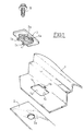
- Figure 1 shows schematically the mounting of a plastic wing 1 on a support metal 2 using the fixing device according to the invention.
- This device comprises a fixing element which is fixed on the support metallic 2 through a longitudinal light practiced in the wing plastic 1.
- the element of fixing consists of a plate 3 having on its underside a longitudinal shoe 4 of smaller width and sliding inside the longitudinal light 1a, said plate 3 being pierced, perpendicular to its plane, by a fixing hole 3a opening at through the longitudinal shoe 4.
- the longitudinal light has a rectangular shape slightly wider than the shoe 4 but longer.
- the plate 3 has a tongue 5a emerging laterally from one side of pad 4, spaced from the surface lower 3b of the wafer 3 by a distance slightly greater than the thickness of the corresponding edge of the light la, edge which comprises a cutout 1b for introducing said tongue 5a.
- the plate 3 has two additional tabs 5b, 5c arranged on the side of the pad 4 opposite to that carrying the first tab 5a, separated from the lower surface 3b of the wafer 3 from a distance slightly greater than the thickness of the corresponding edge of light la.
- the mounting is carried out as follows: the plate 3 is threaded, by its side comprising two tabs 5b, 5c, in the light 1a, on the side opposite the cut 1b, the two tabs 5b, 5c being slid under the wing surface 1.
- the assembly continues by introducing the tongue 5a in cutout 1b then by sliding the plate 3 longitudinally so as to bring the tongue 5a below the lower surface 3b in a position offset from cutout 1b, as it is shown in section in Figure 3.
- the plate 3 is then held on the wing which is blocked between the tongues 5a, 5b, 5c and the surface lower 3b of said wafer.
- the wing 1 thus positioned is held perpendicularly at the plane of the plate 3 while being able to slide according to its dimension longitudinal.
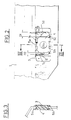
- the plate 3 comprises a first 7 and a second 8 elastic blades, for example obtained by molding with the pad 4 and the plate 3, as it is shown in Figure 4.
- the first blade 7 arises at a end of skate 4 opposite the first end 1d of the light la and extends to said first end 1d.
- This first blade 7 thus defines a first clearance D1.
- the second blade 8 takes birth at the other end of skate 4 to extend until the second end 1c of the light 1a and thus defines a second clearance D2.
- the wing 1 will expand, mainly according to its longitudinal dimension.
- the wing shown on Figure 2 corresponds to a front wing of the vehicle. As such, it is also attached to the front door which is not shown on the Figure 2 but whose location corresponds to the right of wing 1.
- the expansion will result in a translation to the left, of wing 1 and as a result of the light la, with respect to the metal support 2 and therefore to the plate 3 attached to it.
- the force exerted by the expansion being greater than that exerted by the blade 7, the 1d end of the light goes approach the end opposite the shoe 4.
- the travel D1 is obviously chosen according to the expected expansion.
- wing 1 and with it, its light gradually go move to the right to return to their starting position shown in Figure 2.
- the plastic constituting the wing 1 undergoes an additional withdrawal beyond its starting position.
- the lc end light will therefore move to the right in Figure 2, compressing the blade 8.
- the travel D2 is chosen so as to allow the removal of wing 1.
- the D1 travel is greater than D2 travel.
- the elastic return forces of the blades 7 and 8 are determined to be sufficient to ensure the positioning of the plate 3 within the lumen so as to maintain the deflections D1 and D2 chosen while not opposing the free expansion and free removal of the wing 1.
Description
L'invention concerne un dispositif de fixation d'un élément plastique de carrosserie, notamment une aile plastique de véhicule automobile sur un support métallique.The invention relates to a device for fixing a plastic element of bodywork, in particular a plastic wing of a motor vehicle on a metal support.
L'invention concerne plus particulièrement un dispositif de fixation d'un élément plastique de carrosserie sur un support métallique dont le coefficient de dilatation est inférieur à celui dudit élément plastique.The invention relates more particularly to a device for fixing a plastic bodywork element on a metal support, the coefficient of expansion is lower than that of said plastic element.
Certains modèles de véhicules automobiles sont équipés d'ailes en matière plastique. Les coefficients de dilatation étant différents entre la matière plastique constituant les ailes et l'acier constituant la structure, on constate, lors de l'application d'un traitement de surface nécessitant une augmentation de température, par exemple lors de la cuisson d'une peinture, un déplacement important de l'aile par rapport à la structure puis son retour, lors du refroidissement, en position initiale. Les dispositifs de fixation utilisés avec des ailes en acier ne sont donc pas utilisables tels quels pour la fixation des ailes en matière plastique, car ils imposeraient au plastique des contraintes rédhibitoires.Certain models of motor vehicles are equipped with plastic. The coefficients of expansion being different between the material plastic constituting the wings and the steel constituting the structure, we notes, when applying a surface treatment requiring a temperature increase, for example when cooking a painting, a significant displacement of the wing compared to the structure then its return, upon cooling, to the initial position. The devices fixing used with steel wings are therefore not usable as which for fixing the plastic wings, because they would impose to plastic unacceptable constraints.
La publication FR-A-2720794 décrit un dispositif de retenue d'un élément plastique de carrosserie sur un support métallique dans lequel une agrafe de fixation dudit élément plastique sur le support dont le coefficient de dilatation est inférieur à celui de l'élément plastique, est constituée notamment par une base de fixation, la base de fixation portant perpendiculairement des languettes d'appui sur l'élément plastique, lesdites languettes étant solidaires d'une entretoise munie d'un trou de passage d'une vis de fixation. Un tel dispositif ne se justifie que lorsque la fixation s'effectue sur une partie de l'aile présentant une configuration géométrique très particulière. De plus, les variations de température provoquent un retrait supplémentaire du plastique en deçà des dimensions initiales de l'aile, retrait qui n'intervient qu'après le refroidissement, alors que l'aile est à nouveau bloquée longitudinalement sur l'agrafe. Ce retrait, qui n'est pas pris en compte par le dispositif de retenue mentionné ci-dessus, provoque, dans le cas d'une aile avant, un écartement de l'extrémité arrière de ladite aile par rapport à l'extrémité avant de la porte avant, entraínant une augmentation disgracieuse du jeu d'aspect existant entre l'aile et la porte.The publication FR-A-2720794 describes a device for retaining an element body plastic on a metal support in which a staple for fixing said plastic element to the support, the coefficient of expansion is less than that of the plastic element, consists in particular by a fixing base, the fixing base carrying perpendicularly support tabs on the plastic element, said tabs being integral with a spacer provided with a through hole a fixing screw. Such a device is only justified when the attachment takes place on a part of the wing with a geometric configuration very special. In addition, temperature variations cause a additional shrinkage of the plastic below the initial dimensions of the wing, withdrawal which occurs only after cooling, while the wing is again locked longitudinally on the clip. This withdrawal, which is not not taken into account by the above-mentioned restraint, causes, in the case of a front wing, a separation of the end rear of said wing relative to the front end of the front door, causing an unsightly increase in the play of appearance existing between the wing and the door.
Le dispositif selon l'invention vise à palier cet inconvénient. A cet effet, l'invention concerne un dispositif de fixation d'un élément plastique de carrosserie sur un support métallique dont le coefficient de dilatation est inférieur à celui dudit élément plastique , dispositif du type comportant un élément de fixation venant se fixer sur le support métallique à travers une lumière longitudinale de l'élément plastique, caractérisé en ce que ledit élément de fixation est monté en translation longitudinale dans ladite lumière et coopère avec des moyens élastiques procurant le rappel de l'élément de fixation dans une position d'équilibre au sein de la lumière. Le dispositif de fixation ainsi défini permet de prendre en compte les déformations éventuelles de l'élément plastique tout en procurant un positionnement précis dudit élément plastique sur le support métallique.The device according to the invention aims to overcome this drawback. To this end, the invention relates to a device for fixing a plastic element of bodywork on a metal support whose coefficient of expansion is lower than that of said plastic element, device of the type comprising a fixing element which is fixed on the metal support through a longitudinal light of the plastic element, characterized in that said fastening element is mounted in longitudinal translation in said light and cooperates with elastic means providing the recall of the fastener in an equilibrium position within the lumen. The fixing device thus defined makes it possible to take into account the possible deformations of the plastic element while providing a precise positioning of said plastic element on the metal support.
Selon une autre caractéristique de l'invention, la position d'équilibre est
telle que le débattement de l'élément de fixation dans la lumière de
l'élément plastique est réparti, autour de la position d'équilibre:
Selon une autre caractéristique de l'invention, le premier débattement est différent du second débattement. Cette caractéristique permet de prendre en compte le fait que les variations résultant de la dilatation et celles résultant du retrait sont d'amplitude différente.According to another characteristic of the invention, the first travel is different from the second travel. This feature allows you to take take into account that the variations resulting from the expansion and those resulting from the withdrawal are of different amplitude.
Selon une autre caractéristique de l'invention, l'élément de fixation comporte des moyens de détrompage pour son positionnement sur l'élément plastique. Cette caractéristique permet d'éviter une inversion, au moment du montage, de l'élément de fixation, permutation qui entraínerait une permutation entre les deux débattements d'amplitude différente.According to another characteristic of the invention, the fixing element includes keying means for positioning it on the plastic element. This characteristic makes it possible to avoid inversion, moment of assembly, of the fixing element, permutation which would cause a permutation between the two deflections of different amplitude.
Selon une autre caractéristique de l'invention, l'élément de fixation est constitué d'une plaquette comportant sur sa face inférieure un patin longitudinal de largeur inférieure et coulissant à l'intérieur de la lumière, ladite plaquette étant percée, perpendiculairement à son plan, par un trou de fixation.According to another characteristic of the invention, the fixing element is consisting of a plate having on its underside a pad longitudinal of lower width and sliding inside the light, said plate being pierced, perpendicular to its plane, by a hole of fixation.
Selon une autre caractéristique de l'invention, les moyens élastiques sont constitués par une première et une seconde lames élastiques fixées sur le patin, la première lame s'étendant depuis la partie arrière du patin jusqu'à la première extrémité de la lumière, définissant ainsi le premier débattement, la seconde lame s'étendant depuis la partie avant du patin jusqu'à la seconde extrémité de la lumière, définissant ainsi le second débattement.According to another characteristic of the invention, the elastic means are constituted by first and second elastic blades fixed on the skate, the first blade extending from the rear part of the skate to the first end of the light, thus defining the first travel, the second blade extending from the front part of the skate to the second end of the light, defining the second travel.
Selon une autre caractéristique de l'invention, les moyens de détrompage comprennent une première languette émergeant latéralement d'un côté du patin, écartée de la surface inférieure de la plaquette d'une distance légèrement supérieure à l'épaisseur du bord correspondant de la lumière, bord qui comporte une découpe d'introduction de ladite languette.According to another characteristic of the invention, the polarizing means include a first tab emerging laterally from one side of the pad, spaced from the bottom surface of the pad by a distance slightly greater than the thickness of the corresponding edge of the light, edge which includes a cutout for introducing said tongue.
Selon une autre caractéristique de l'invention, les moyens de détrompage comprennent deux languettes supplémentaires disposées du côté opposé à celui portant la première languette, écartés de la surface inférieure de la plaquette d'une distance légèrement supérieure à l'épaisseur du bord correspondant de la lumière. Ces languettes permettent de solidariser le dispositif de fixation sur l'aile plastique à fixer, et ce, préalablement à son montage sur le support métallique, ce qui facilite les manipulations. L'élément de fixation ainsi défini est particulièrement simple et peu coûteux à fabriquer. En particulier, il peut être réalisé en matière plastique et être moulé en une seule pièce avec les lames élastiques.According to another characteristic of the invention, the polarizing means include two additional tabs on the side opposite the one with the first tab, spaced from the bottom surface of the insert a distance slightly greater than the thickness of the edge light correspondent. These tabs are used to secure the fixing device on the plastic wing to be fixed, prior to its mounting on the metal support, which facilitates handling. The fixing element thus defined is particularly simple and not very expensive to manufacture. In particular, it can be made of plastic and be molded in one piece with the elastic blades.
D'autres caractéristiques et avantages apparaítront à la lecture de la description d'un exemple de dispositif selon l'invention, en référence aux dessins dans lesquels :
- la figure 1 est une vue en perspective éclatée du montage de l'aile sur le support au moyen du dispositif de fixation selon l'invention,
- la figure 2 est une vue en plan du dispositif de fixation selon l'invention,
- la figure 3 est une vue en coupe selon la ligne III-III de la figure 2,
- la figure 4 est une vue en perspective de l'élément de fixation en position retournée.
- FIG. 1 is an exploded perspective view of the mounting of the wing on the support by means of the fixing device according to the invention,
- FIG. 2 is a plan view of the fixing device according to the invention,
- FIG. 3 is a sectional view along line III-III of FIG. 2,
- Figure 4 is a perspective view of the fastening element in the inverted position.
La figure 1 schématise le montage d'une aile plastique 1 sur un support
métallique 2 à l'aide du dispositif de fixation selon l'invention. Ce
dispositif comporte un élément de fixation venant se fixer sur le support
métallique 2 à travers une lumière longitudinale la pratiquée dans l'aile
plastique 1. Dans la variante représentée sur les figures, l'élément de
fixation est constitué d'une plaquette 3 comportant sur sa face inférieure
un patin longitudinal 4 de largeur inférieure et coulissant à l'intérieur de la
lumière longitudinale 1a, ladite plaquette 3 étant percée,
perpendiculairement à son plan, par un trou de fixation 3a débouchant à
travers le patin longitudinal 4. La lumière longitudinale la présente une
forme rectangulaire de largeur légèrement supérieure à celle du patin 4
mais de longueur supérieure. La plaquette 3 comporte une languette 5a
émergeant latéralement d'un côté du patin 4, écartée de la surface
inférieure 3b de la plaquette 3 d'une distance légèrement supérieure à
l'épaisseur du bord correspondant de la lumière la, bord qui comporte une
découpe 1b d'introduction de ladite languette 5a.Figure 1 shows schematically the mounting of a plastic wing 1 on a
La plaquette 3 comporte deux languettes supplémentaires 5b,5c disposées
du côté du patin 4 opposé à celui portant la première languette 5a, écartées
de la surface inférieure 3b de la plaquette 3 d'une distance légèrement
supérieure à l'épaisseur du bord correspondant de la lumière la. Le
montage s'effectue de la manière suivante : la plaquette 3 est enfilée, par
son côté comportant deux languettes 5b,5c, dans la lumière la, du côté
opposé à la découpe 1b, les deux languettes 5b,5c étant glissées sous la
surface de l'aile 1. Le montage se poursuit en introduisant la languette 5a
dans la découpe 1b puis en faisant glisser longitudinalement la plaquette 3
de manière à amener la languette 5a en dessous de la surface inférieure 3b
dans une position décalée par rapport à la découpe 1b, comme il est
représenté en coupe sur la figure 3. La plaquette 3 est alors maintenue sur
l'aile qui se trouve bloquée entre les languettes 5a,5b,5c et la surface
inférieure 3b de ladite plaquette. On vient ensuite fixer l'aile sur le
support 2 à l'aide d'une vis 6 qui traverse le trou 3a pratiqué au travers la
plaquette 3 et son patin 4, pour venir se visser dans un trou 2a du support
métallique 2. L'aile 1 ainsi positionnée est maintenue perpendiculairement
au plan de la plaquette 3 tout en pouvant glisser selon sa dimension
longitudinale.The
De manière à s'assurer que l'aile 1 soit correctement positionnée par
rapport au support métallique 2, et donc par rapport au reste du véhicule,
il est nécessaire que le positionnement de la plaquette 3 soit déterminé par
rapport à ladite aile 1. De plus, de manière à autoriser les dilatations et
retraits intervenant à la suite d'un traitement thermique subi par la caisse
du véhicule, il est nécessaire que ce positionnement soit réalisé de manière
élastique de part et d'autre d'une position d'équilibre. A cet effet, la
plaquette 3 comporte une première 7 et une seconde 8 lames élastiques,
par exemple obtenues de moulage avec le patin 4 et la plaquette 3, comme
il est représenté sur la figure 4. La première lame 7 prend naissance à une
extrémité du patin 4 en regard de la première extrémité 1d de la
lumière la et s'étend jusqu'à ladite première extrémité 1d. Cette première
lame 7 définit ainsi un premier débattement D1. La seconde lame 8 prend
naissance à l'autre extrémité du patin 4 pour s'étendre jusqu'à la seconde
extrémité 1c de la lumière 1a et définit ainsi un second débattement D2.In order to ensure that the wing 1 is correctly positioned by
compared to the
Lors du montage de l'aile sur le support métallique 2, on effectue le
réglage des jeux entre l'aile 1, le capot et la porte (non représentés sur les
figures). La plaquette 3 étant maintenue dans sa position d'équilibre par
rapport à l'aile entre les lames élastiques 7,8, l'ajustement est réalisé
grâce au trou 3a, percé dans la plaquette 3 avec un diamètre supérieur à
celui de la vis 6. Les lames 7 et 8 permettent d'assurer le respect des
débattements D1 et D2 de part et d'autre de la position d'équilibre de la
plaquette 3 à l'intérieur de l'évidement la, comme il est représenté sur la
figure 2.When mounting the wing on the
Lors d'une élévation importante de température, l'aile 1 va se dilater,
principalement selon sa dimension longitudinale. L'aile représentée sur
la figure 2 correspond à une aile avant de véhicule. A ce titre, elle est
également fixée au niveau de la porte avant qui n'est pas représentée sur la
figure 2 mais dont l'emplacement correspond à la droite de l'aile 1. Ainsi,
la dilatation va se traduire par une translation vers la gauche, de l'aile 1 et
par suite de la lumière la, par rapport au support métallique 2 et donc à la
plaquette 3 qui lui est fixée. La force exercée par la dilatation étant
supérieure à celle exercée par la lame 7, l'extrémité 1d de la lumière la va
se rapprocher de l'extrémité en regard du patin 4. Le débattement D1 est
évidemment choisi en fonction de la dilatation prévue. Lors du
refroidissement, l'aile 1 et avec elle, sa lumière la vont petit à petit se
déplacer vers la droite pour reprendre leur position de départ représentée
sur la figure 2. Après refroidissement, le plastique constituant l'aile 1 subit
un retrait supplémentaire au-delà de sa position de départ. L'extrémité lc
de la lumière la va donc se déplacer vers la droite de la figure 2, en
comprimant la lame 8. Le débattement D2 est choisi de manière à
permettre le retrait de l'aile 1. Généralement le débattement D1 est
supérieur au débattement D2. Les forces de rappel élastique des lames 7 et
8 sont déterminées de façon à être suffisantes pour assurer le
positionnement de la plaquette 3 au sein de la lumière la de manière à
maintenir les débattements D1 et D2 choisis tout en ne s'opposant pas à la
libre dilatation et au libre retrait de l'aile 1.During a significant rise in temperature, the wing 1 will expand,
mainly according to its longitudinal dimension. The wing shown on
Figure 2 corresponds to a front wing of the vehicle. As such, it is
also attached to the front door which is not shown on the
Figure 2 but whose location corresponds to the right of wing 1. Thus,
the expansion will result in a translation to the left, of wing 1 and
as a result of the light la, with respect to the
La disposition asymétrique des languettes 5a, d'un côté du patin 4 de la
plaquette 3 et 5b,5c de l'autre côté, permet de s'assurer que ladite
plaquette 3 n'est pas montée à l'envers, ce qui aurait pour conséquence
d'inverser les deux débattements Dl et D2, qui, comme on l'a vu ci-dessus,
ne sont pas forcément égaux.The asymmetrical arrangement of the
Bien entendu, l'invention n'est nullement limitée au mode de réalisation décrit et illustré qui n'a été donné qu'à titre d'exemple. En particulier, tout élément de fixation monté à translation à l'intérieur d'une lumière pratiquée dans l'aile et maintenu en place au sein de ladite lumière par des moyens élastiques solidaires de l'élément de fixation ou de la lumière ne sortirait pas du cadre de l'invention définie par les revendications.Of course, the invention is in no way limited to the embodiment described and illustrated which has been given only by way of example. In particular, any fastening element mounted in translation inside a light practiced in the wing and held in place within said lumen by elastic means secured to the fixing element or to the light do not would not depart from the scope of the invention defined by the claims.
Claims (7)
- A device for fastening a plastic bodywork member (1) on a metal support (2) whose coefficient of expansion is lower than that of the plastic member (1), which device is of the type comprising a fastening member (3, 4) which is fastened on the metal support (2) via a longitudinal slot (1a) of the plastic member (1), this fastening member (3, 4) being mounted to move in longitudinal translation in the slot (1a) and cooperating with elastic means (7, 8), characterised in that these elastic means recall the fastening member (3, 4) into a balanced position such that the clearance of the fastening member (3, 4) in the slot (1a) of the plastic member (1) is divided, around the balanced position:into a first clearance (D1) defined by the space between a first end (1d) of the slot (1a) and the facing end of the fastening member (3, 4), which clearance corresponds to the expansion of the plastic member (1) and,a second clearance (D2) defined by the space between the second end (1c) of the slot (1a) and the facing end of the fastening member (3, 4), which clearance corresponds to the contraction of this plastic member (1).
- A fastening device as claimed in claim 1, characterised in that the first clearance (D1) is different from the second clearance (D2).
- A fastening device as claimed in any one of claims 1 and 2, characterised in that the fastening member (3, 4) comprises correction means (5a, 5b, 5c) for its positioning on the plastic member (1).
- A fastening device as claimed in claim 3, characterised in that the fastening member is formed by a plate (3) comprising, on its lower surface (3b), a longitudinal block (4) of smaller width sliding within the slot (1a), a fastening hole (3a) being drilled into this plate (3), perpendicular to its plane.
- A fastening device as claimed in the preceding claim, characterised in that the elastic means are formed by a first and a second elastic blade (7, 8) secured to the block (4), the first blade (7) extending from the rear portion of the block (4) to the first end (1d) of the slot (1a), thereby defining the first clearance (D1), and the second blade (8) extending from the front portion of the block (4) to the second end (1c) of the slot (1a), thereby defining the second clearance (D2).
- A fastening device as claimed in any one of claims 4 or 5, characterised in that the correction means comprise a first tongue (5a) emerging laterally from one side of the block (4), spaced from the lower surface (3b) of the plate (3) by a distance slightly greater than the thickness of the corresponding edge of the slot (1a), which edge comprises a cut-out (1b) for the introduction of this tongue (5a).
- A fastening device as claimed in the preceding claim, characterised in that the correction means comprise two further tongues (5b, 5c) disposed on the side opposite to that bearing the first tongue (5a), spaced from the lower surface (3b) of the plate (3) by a distance slightly greater than the thickness of the corresponding edge of the slot (1a).
Applications Claiming Priority (2)
| Application Number | Priority Date | Filing Date | Title |
|---|---|---|---|
| FR9604317 | 1996-04-05 | ||
| FR9604317A FR2747091B1 (en) | 1996-04-05 | 1996-04-05 | SLIDING FIXING DEVICE OF A PLASTIC WING |
Publications (2)
| Publication Number | Publication Date |
|---|---|
| EP0799758A1 EP0799758A1 (en) | 1997-10-08 |
| EP0799758B1 true EP0799758B1 (en) | 2000-06-21 |
Family
ID=9490968
Family Applications (1)
| Application Number | Title | Priority Date | Filing Date |
|---|---|---|---|
| EP19970400713 Expired - Lifetime EP0799758B1 (en) | 1996-04-05 | 1997-03-28 | Device for sliding attachment of a plastic mud guard |
Country Status (4)
| Country | Link |
|---|---|
| EP (1) | EP0799758B1 (en) |
| DE (1) | DE69702324T2 (en) |
| ES (1) | ES2146963T3 (en) |
| FR (1) | FR2747091B1 (en) |
Cited By (2)
| Publication number | Priority date | Publication date | Assignee | Title |
|---|---|---|---|---|
| EP1319581A2 (en) | 2001-12-11 | 2003-06-18 | Volkswagen Aktiengesellschaft | Plastic mud-guard for motor vehicles |
| DE102005033351A1 (en) * | 2005-07-16 | 2007-01-18 | Volkswagen Ag | Structural member e.g. fender for motor vehicle, has stretchable element e.g. tape, acryl foam, to absorb variations in coefficient of thermal expansion of either base or reinforcing member |
Families Citing this family (22)
| Publication number | Priority date | Publication date | Assignee | Title |
|---|---|---|---|---|
| FR2771992B1 (en) | 1997-12-05 | 1999-12-31 | Renault | DEVICE FOR FIXING A VEHICLE SIDE FENDER ON A SUPPORT ELEMENT |
| FR2776721B1 (en) | 1998-03-31 | 2000-06-09 | Plastic Omnium Cie | SLIDING FIXATION OF A PLASTIC PART ON A SUPPORT |
| DE19824977B4 (en) * | 1998-06-04 | 2007-11-08 | Volkswagen Ag | Process for coating a body component and a body of a motor vehicle |
| DE19851494B4 (en) * | 1998-11-09 | 2008-04-10 | Volkswagen Ag | Spacer element for a body part to be coated in an electrodeposition bath and method for its production |
| FR2796996B1 (en) | 1999-07-27 | 2001-10-12 | Plastic Omnium Cie | FUSIBLE SLIDING ATTACHMENT OF A PLASTIC PART ON A SUPPORT |
| FR2806133B1 (en) * | 2000-03-08 | 2002-06-14 | Peugeot Citroen Automobiles Sa | CLIP FOR FIXING A BODY ELEMENT ON THE STRUCTURE OF A MOTOR VEHICLE |
| JP3863715B2 (en) * | 2000-10-06 | 2006-12-27 | 株式会社パイオラックス | Resin panel fixing structure |
| DE10153569A1 (en) * | 2001-10-30 | 2003-05-22 | Raymond A & Cie | Fastening clamp for connecting panels with different expansion behavior |
| US7731444B2 (en) | 2001-11-30 | 2010-06-08 | Renault S.A.S. | Device for coupling a plastic part and a body shell structure |
| DE20120423U1 (en) | 2001-12-18 | 2002-05-02 | Rehau Ag & Co | Elements for slidable fastening of components |
| DE10213168A1 (en) * | 2002-03-23 | 2003-10-02 | Bayerische Motoren Werke Ag | Plastic fender of a motor vehicle |
| US6929313B2 (en) | 2002-03-23 | 2005-08-16 | Bayerische Motoren Werke Aktiengesellschaft | Plastic fender for a motor vehicle and device for fastening the same |
| DE10231099A1 (en) * | 2002-07-10 | 2004-02-19 | Bayerische Motoren Werke Ag | Plastic wing attachment system for motor vehicle has elongated hole in wing in which joint bush is inserted |
| DE10343744B4 (en) * | 2003-09-22 | 2017-02-16 | Volkswagen Ag | Fastening arrangement between a fastening part and a body part of a motor vehicle |
| FR2877060B1 (en) * | 2004-10-25 | 2007-03-30 | Fci Expansion 2 Sa | PIECE PROVIDED WITH MEANS OF FASTENING ON ANOTHER PART COMPRISING A PASSAGE AND AT LEAST ONE INSERT OF REINFORCEMENT |
| DE102005057603A1 (en) * | 2005-12-02 | 2007-06-06 | Volkswagen Ag | Motor vehicle`s body part e.g. plastic mudguard, arrangement, has clearance hole and fastening unit formed, such that unit is mountable in two positions, where thermal expansion of body part in one position is larger than in other position |
| DE102006028591B4 (en) * | 2006-06-22 | 2019-02-07 | Volkswagen Ag | Arrangement of a body part on a support part of a motor vehicle |
| DE102009011546A1 (en) * | 2009-03-03 | 2010-09-09 | Bayerische Motoren Werke Aktiengesellschaft | Component and sliding element |
| FR2969106B1 (en) * | 2010-12-16 | 2012-12-28 | Peugeot Citroen Automobiles Sa | FRONT FENDER FOR A MOTOR VEHICLE, OF PLASTIC MATERIAL OR LIGHT METAL, VEHICLE EQUIPPED WITH SUCH A WING AND METHOD OF MOUNTING |
| ITMO20120136A1 (en) * | 2012-05-25 | 2013-11-26 | Lodi Luigi & Figli S R L | SUPPORT FOR A MUDGUARD. |
| EP2722258A1 (en) * | 2012-10-17 | 2014-04-23 | Compagnie Plastic Omnium | Motor-vehicle component capable of withstanding thermal deformation |
| DE102016215033A1 (en) | 2016-08-11 | 2018-02-15 | Bayerische Motoren Werke Aktiengesellschaft | Movement tolerant attachment device |
Family Cites Families (4)
| Publication number | Priority date | Publication date | Assignee | Title |
|---|---|---|---|---|
| US4529244A (en) * | 1982-11-19 | 1985-07-16 | General Motors Corporation | Plastic vehicle body panel mounting structure |
| DE3809385A1 (en) * | 1988-03-19 | 1989-09-28 | Happich Gmbh Gebr | Vehicle fitting |
| US5098765A (en) * | 1989-12-22 | 1992-03-24 | Chrysler Corportion | Fastening arrangement for plastic vehicle panel |
| FR2720794B1 (en) * | 1994-06-01 | 1996-07-12 | Renault | Device for retaining a plastic bodywork element on a metal support and method for mounting the device. |
-
1996
- 1996-04-05 FR FR9604317A patent/FR2747091B1/en not_active Expired - Fee Related
-
1997
- 1997-03-28 DE DE1997602324 patent/DE69702324T2/en not_active Expired - Lifetime
- 1997-03-28 ES ES97400713T patent/ES2146963T3/en not_active Expired - Lifetime
- 1997-03-28 EP EP19970400713 patent/EP0799758B1/en not_active Expired - Lifetime
Cited By (2)
| Publication number | Priority date | Publication date | Assignee | Title |
|---|---|---|---|---|
| EP1319581A2 (en) | 2001-12-11 | 2003-06-18 | Volkswagen Aktiengesellschaft | Plastic mud-guard for motor vehicles |
| DE102005033351A1 (en) * | 2005-07-16 | 2007-01-18 | Volkswagen Ag | Structural member e.g. fender for motor vehicle, has stretchable element e.g. tape, acryl foam, to absorb variations in coefficient of thermal expansion of either base or reinforcing member |
Also Published As
| Publication number | Publication date |
|---|---|
| ES2146963T3 (en) | 2000-08-16 |
| DE69702324T2 (en) | 2001-01-25 |
| FR2747091B1 (en) | 1998-05-07 |
| FR2747091A1 (en) | 1997-10-10 |
| EP0799758A1 (en) | 1997-10-08 |
| DE69702324D1 (en) | 2000-07-27 |
Similar Documents
| Publication | Publication Date | Title |
|---|---|---|
| EP0799758B1 (en) | Device for sliding attachment of a plastic mud guard | |
| EP1326024B1 (en) | Fastening for joining a piece to a support and to position it in relation to its environment, especially an automobile body part | |
| EP1854706A1 (en) | Sliding attachment of a flange to a body-in-white of an automobile vehicle and attachment method using same | |
| FR2707944A1 (en) | Adjustable stopper, abutment system comprising it and method for obtaining such a system. | |
| FR2762557A1 (en) | ARTICLE COMPRISING TWO ELEMENTS ARTICULATED ONE IN RELATION TO THE OTHER | |
| EP0799759B1 (en) | Device for carrying a plastic mud guard on a metallic body | |
| FR2768197A1 (en) | Fixing plate for joining vehicle bodywork | |
| EP1669269A1 (en) | Self locking joint between a ball head actuating rod and a flat part | |
| EP0995648A1 (en) | Anti-theft device for steering column with means for blocking the bolt | |
| EP1258389B1 (en) | Closure device for an opening in a wall for fastening an object, such as an automotive vehicle seat | |
| EP3038882B1 (en) | Fastening device with two use modes and motor vehicle comprising such a device | |
| FR2871759A1 (en) | ANTI-THEFT ANTI-THEFT DEVICE WITH INSERABLE LOCK, IN PARTICULAR FOR A MOTOR VEHICLE | |
| FR2895962A1 (en) | Body element fixing support part for motor vehicle, has blade delimiting guiding slide for guiding slugs which are mounted sliding in slide defining guiding direction, after rupture or each connection, and frangible connection | |
| WO2022233609A1 (en) | Adapter for a wiping system | |
| FR2778705A1 (en) | ROOF BAR SUPPORT FOR MOTOR VEHICLE | |
| FR2994932A1 (en) | Device for assembly of two parts such as case and garnishing element, of car by sliding, has strip extending into introduction and locking parts arranged to retain fixing strip in-between according to all directions in blocking position | |
| EP0864763B1 (en) | Releasable connector in particular for a body element | |
| EP0459849B1 (en) | Adjustable mounting for motor vehicule bumper | |
| EP1449993A1 (en) | Vehicle door handle comprising locking means of an external element. | |
| EP3938667B1 (en) | Pyrotechnic nut releasing device | |
| FR2768196A1 (en) | Fixing plate for vehicle bodywork sections | |
| EP3552890B1 (en) | Device for locking a steering column of a motor vehicle | |
| FR2772441A1 (en) | Fastening e.g. for trim component, e.g. bumper or aerodynamic fin, on motor vehicle body | |
| EP2006155A1 (en) | Device for tamper-proof attachment of a part in a cut-out made in a structure | |
| EP1452398B1 (en) | Profile for a motor vehicle door and its production process |
Legal Events
| Date | Code | Title | Description |
|---|---|---|---|
| PUAI | Public reference made under article 153(3) epc to a published international application that has entered the european phase |
Free format text: ORIGINAL CODE: 0009012 |
|
| AK | Designated contracting states |
Kind code of ref document: A1 Designated state(s): BE DE ES GB IT |
|
| 17P | Request for examination filed |
Effective date: 19980310 |
|
| GRAG | Despatch of communication of intention to grant |
Free format text: ORIGINAL CODE: EPIDOS AGRA |
|
| 17Q | First examination report despatched |
Effective date: 19990817 |
|
| GRAG | Despatch of communication of intention to grant |
Free format text: ORIGINAL CODE: EPIDOS AGRA |
|
| GRAH | Despatch of communication of intention to grant a patent |
Free format text: ORIGINAL CODE: EPIDOS IGRA |
|
| GRAH | Despatch of communication of intention to grant a patent |
Free format text: ORIGINAL CODE: EPIDOS IGRA |
|
| GRAA | (expected) grant |
Free format text: ORIGINAL CODE: 0009210 |
|
| AK | Designated contracting states |
Kind code of ref document: B1 Designated state(s): BE DE ES GB IT |
|
| RIN1 | Information on inventor provided before grant (corrected) |
Inventor name: GINESTET, THIERRY |
|
| ITF | It: translation for a ep patent filed |
Owner name: JACOBACCI & PERANI S.P.A. |
|
| REF | Corresponds to: |
Ref document number: 69702324 Country of ref document: DE Date of ref document: 20000727 |
|
| REG | Reference to a national code |
Ref country code: ES Ref legal event code: FG2A Ref document number: 2146963 Country of ref document: ES Kind code of ref document: T3 |
|
| GBT | Gb: translation of ep patent filed (gb section 77(6)(a)/1977) |
Effective date: 20000815 |
|
| PLBE | No opposition filed within time limit |
Free format text: ORIGINAL CODE: 0009261 |
|
| STAA | Information on the status of an ep patent application or granted ep patent |
Free format text: STATUS: NO OPPOSITION FILED WITHIN TIME LIMIT |
|
| 26N | No opposition filed | ||
| REG | Reference to a national code |
Ref country code: GB Ref legal event code: IF02 |
|
| PGFP | Annual fee paid to national office [announced via postgrant information from national office to epo] |
Ref country code: GB Payment date: 20120322 Year of fee payment: 16 Ref country code: BE Payment date: 20120329 Year of fee payment: 16 |
|
| BERE | Be: lapsed |
Owner name: *RENAULT Effective date: 20130331 |
|
| GBPC | Gb: european patent ceased through non-payment of renewal fee |
Effective date: 20130328 |
|
| PG25 | Lapsed in a contracting state [announced via postgrant information from national office to epo] |
Ref country code: GB Free format text: LAPSE BECAUSE OF NON-PAYMENT OF DUE FEES Effective date: 20130328 Ref country code: BE Free format text: LAPSE BECAUSE OF NON-PAYMENT OF DUE FEES Effective date: 20130331 |
|
| PGFP | Annual fee paid to national office [announced via postgrant information from national office to epo] |
Ref country code: DE Payment date: 20150320 Year of fee payment: 19 Ref country code: IT Payment date: 20150326 Year of fee payment: 19 Ref country code: ES Payment date: 20150326 Year of fee payment: 19 |
|
| REG | Reference to a national code |
Ref country code: DE Ref legal event code: R119 Ref document number: 69702324 Country of ref document: DE |
|
| PG25 | Lapsed in a contracting state [announced via postgrant information from national office to epo] |
Ref country code: DE Free format text: LAPSE BECAUSE OF NON-PAYMENT OF DUE FEES Effective date: 20161001 |
|
| PG25 | Lapsed in a contracting state [announced via postgrant information from national office to epo] |
Ref country code: IT Free format text: LAPSE BECAUSE OF NON-PAYMENT OF DUE FEES Effective date: 20160328 |
|
| REG | Reference to a national code |
Ref country code: ES Ref legal event code: FD2A Effective date: 20180507 |
|
| PG25 | Lapsed in a contracting state [announced via postgrant information from national office to epo] |
Ref country code: ES Free format text: LAPSE BECAUSE OF NON-PAYMENT OF DUE FEES Effective date: 20160329 |