EP1319581A2 - Plastic mud-guard for motor vehicles - Google Patents
Plastic mud-guard for motor vehicles Download PDFInfo
- Publication number
- EP1319581A2 EP1319581A2 EP02025208A EP02025208A EP1319581A2 EP 1319581 A2 EP1319581 A2 EP 1319581A2 EP 02025208 A EP02025208 A EP 02025208A EP 02025208 A EP02025208 A EP 02025208A EP 1319581 A2 EP1319581 A2 EP 1319581A2
- Authority
- EP
- European Patent Office
- Prior art keywords
- fender
- mudguard according
- stiffening
- stiffening elements
- inner contour
- Prior art date
- Legal status (The legal status is an assumption and is not a legal conclusion. Google has not performed a legal analysis and makes no representation as to the accuracy of the status listed.)
- Granted
Links
Images


Classifications
-
- B—PERFORMING OPERATIONS; TRANSPORTING
- B62—LAND VEHICLES FOR TRAVELLING OTHERWISE THAN ON RAILS
- B62D—MOTOR VEHICLES; TRAILERS
- B62D29/00—Superstructures, understructures, or sub-units thereof, characterised by the material thereof
- B62D29/04—Superstructures, understructures, or sub-units thereof, characterised by the material thereof predominantly of synthetic material
- B62D29/048—Connections therefor, e.g. joints
-
- B—PERFORMING OPERATIONS; TRANSPORTING
- B62—LAND VEHICLES FOR TRAVELLING OTHERWISE THAN ON RAILS
- B62D—MOTOR VEHICLES; TRAILERS
- B62D25/00—Superstructure or monocoque structure sub-units; Parts or details thereof not otherwise provided for
- B62D25/08—Front or rear portions
- B62D25/16—Mud-guards or wings; Wheel cover panels
- B62D25/161—Mud-guards made of non-conventional material, e.g. rubber, plastics
Definitions
- the invention relates to a fender made of plastic on motor vehicles according to the Preamble of claim 1.
- Plastic fenders have long been known in the art The advantage of such fenders is essentially that they are simple and inexpensive Production of the same and the almost unlimited possibilities of training the outer contour.
- the fenders can optionally be made from a Glass fiber reinforced polyurethane resin or from a flexible sheet-molded Polysterverbund manufactured and using known screw connections on the Be attached to the substructure.
- DE 93 01 224.1 is also a simple one Fastening by means of screws through the screw holes in the fender on adjacent beams of the motor vehicle, such as a front cross member and one A pillar disclosed. From DE 197 11 794 A1 it is known Manufacture plastic body shell components using back injection technology.
- DE 40 10 453 A1 has disclosed a solution which in turn provides for the Edge area of a fender, namely the front, the rear and the upper Area, also called fender bench, by means of embedded or applied To keep steel rails on the vehicle body so that they cannot move the fender bulges outwards in the event of thermal expansion.
- the disadvantage here is estimated that this so-called bulging occurs undefined and the fender is predominantly under considerable tension, which occurs in the event of a crash Increased splintering of the fender and extensive scattering of the splinters causes.
- the object of the present invention is to provide a plastic fender, which, on the one hand, is an improved, namely easier to do and Has cheaper mounting concept and also the thermal Expansion of the same in relation to the metal substructure. On the other hand, significant stiffness-increasing and safety-related Measures are shown.
- the task is in connection with the features in the preamble of claim 1 in that the fender in the region of a plurality of Fastening points connecting, guiding and / or stiffening elements are assigned, which are preferably made of plastic and / or metal.
- the connecting, guiding and / or Stiffening elements as separate and prefabricated components on the inner contour of the Fender glued on.
- the connecting, guiding and / or stiffening elements can be applied to the inner contour of the fender both over the entire surface and in some areas be glued on.
- the connection, leadership and / or Stiffening elements glued to the inner contour of the fender so that none Signs are visible on the outer skin of the fender.
- connecting, guiding and / or Stiffening elements made of plastic worked up on the inner contour of the fender, or sprayed on. Furthermore, it is proposed that one or more connecting elements be such Contour that they each have a corresponding Hooking element, which is fixedly arranged on an adjacent body part, form a clamping element.
- the fender and / or one or more Provide connecting elements with one or more holes and each by means of spring-loaded fastening screws on an adjacent body part attached.
- the Bores have a larger inner diameter than the outer diameter of the Bolt.
- An expedient embodiment of the invention provides that one or more Connecting elements with stiffening elements arranged on one or both sides in Form of stiffening ribs are provided, the inner contour of the fender pointing stiffening ribs at the same time spacing ribs for an even Glue application can be.
- the proposed fender has at least one front and a rear connecting element, the front Connecting element introduced into the edge zone of the fender and to positive connection by means of fastening screws to an adjacent one Body part and is formed on a bumper and the rear Connecting element is also introduced into the edge zone of the fender and a Has receptacle for a hooking element engaging in the same, which is fixed is arranged on an adjacent body part.
- the fender is advantageously at least one on the vehicle door side Guide element for a stable installation position on the vehicle and for realizing a assigned uniform joint to the vehicle door.
- At least in the area of a the inside of the wheel arch of the fender is kinked and on the inside the same for stiffening and improved connection of a wheel house shell one or several stiffening elements in the form of arranged parallel to the wheel cutout Ribs are arranged.
- at least one is in upper portion of the fender is formed and located on an adjacent one Body part supporting fender bench on the inside with a plurality of Provide stiffening elements in the form of stiffening ribs.
- the fender has a trim area on, which in turn has one or more support surfaces for the trim with one or several positioning, respectively mounting holes, in the mounting pins of the Intervene trim strip, includes, being on the inner contour of the fender in Trim area one or more stiffening elements in the form of Stiffening ribs are applied.
- the basic structure of the Fender consists of a PUR RIM system and that the adhesive used PUR structural adhesive is.
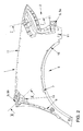
- Fig. 1 shows the external view of a front left fender 1, the left side of the Cutout 2 for a headlight and the wheel cutout 3 can be seen below.
- a trim strip area 4 is arranged, up to which one attached approximately horizontally on the outer skin known and accordingly Decorative strip not shown extends.
- the fender 1 is essentially made of plastic, which is known per se Back injection process can be used.
- PUR-RIM system A basic structure of the fender 1 from one has proven particularly suitable proven so-called PUR-RIM system.
- PUR-RIM systems Groups of polyurethane, from which largely compact, hard elastic, essentially thin-walled and often reinforced with glass fibers Molded parts, such as body outer skin components and thus also fenders 1, getting produced.
- PUR-RIM systems fulfill the increasingly demanding requirements for high dimensional and thermal stability.
- KTL process Cathodic dip coating
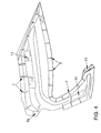
- Fig. 2 shows the inside view of the fender 1 described above with a Many attachment points for attaching the fender 1 to the here not Metallic vehicle body shown in more detail.
- connection points are connecting, guiding and / or Stiffening elements 5, 6, 7 assigned from plastic or metal and can both Cast and pressed parts.
- Light metal casting for example, is a suitable metal casting on.
- PUR-RIM systems are also suitable here, however are any other known and suitable by the invention Plastics recorded.
- connection, guidance and / or Stiffening elements 5, 6, 7 prefabricated and as separate components in the predestined areas on the inside of the prefabricated shell of the Fender 1 glued on.
- the preferred embodiment is a combination of both of the above Embodiments represent.
- a front Connecting element 5a and a rear connecting element 5b prefabricated and by means of an adhesive 8 glued into the edge zones of the inner contour of the fender 1 (FIG. 2) in such a way that no markings are visible on the outer skin of the fender 1 are.
- FIG. 3 and 4 show the front connecting element 5a, which has a plurality is provided by stiffening elements 7 in the form of stiffening ribs.
- the Stiffening ribs can be provided on one or both sides, in the present case on both sides be, with the stiffening ribs facing the inner contour of the fender 1 are spacing ribs for a uniform application of the adhesive 8 at the same time.
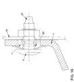
- the front connecting element 5a is also used for the positive connection Fixing screws 9 to an adjacent body part 10 and not to one bumpers provided with holes 11 (Fig. 5).
- connection, Guide and / or stiffening elements 5, 6, 7 on the inner contour of the fender 1 glued. This can be done over the entire area or only in certain areas.
- Fig. 5 shows a preferred embodiment such that the front Connecting element 5a has a hollow shape and only in its Edge areas is connected to the fender 1.
- Stop lugs 12 is such a distance between the actual adhesive surfaces maintained, which is required for wetting with the selected adhesive 8.
- Adhesive 8 a PUR structural adhesive, has proven particularly useful. Due to the hollow shape Shape of the front connecting element 5a during the actual Gluing process is a dodging excessive adhesives 8 to the outside guaranteed.
- the connecting element 5a has a ribbed structure.
- the front connecting elements 5a can also have projections, not shown and pointing towards the body, which on the one hand act as a spacer or also by means of screw or Clamp connections establish the connection to the adjacent body part 11 can.
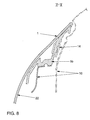
- the basic structure of the rear connecting element 5b corresponds approximately to that of above-described front connecting element 5a. Again, there are a majority of stiffening elements 7 arranged in the form of stiffening ribs (Fig. 7). in the The rear connecting element differs from the front connecting element 5a
- Connecting element 5b has a receptacle 13 for a hooking element 14, which one end detachably engages in the receptacle 13 and the other through Bores 15 through, for example by means of fastening screws on the extended A-pillar of the passenger compartment (not shown) is attached. Both that rear connecting element 5b, respectively their receptacle 13 and the corresponding parts of the hooking element 14 have such a contour, that they form an optionally releasable clamping element (Fig. 8).
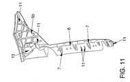
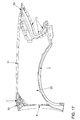
- the above-mentioned guide element 6 is shown, which on the one hand, according to the present exemplary embodiment, in a form-fitting manner on the rear Connecting element 5b and the other, in the edge area of the fender 1 after extending below, is attached to the inner contour thereof, preferably as above spelled out in detail, glued.
- This also has stiffening elements 7 in Form of stiffening ribs.
- the fender 1 has this guide element 6 on the vehicle door side via a stable installation position, which in turn ensures a uniform Joint between fender 1 and vehicle door can be achieved (not shown).
- stiffening elements 7 present a stiffening element 7 in the form of a parallel to the wheel cutout 3 Rib, arranged.
- this can be a separate component glued or already sprayed on during the manufacture of the shell of the fender 1 his. Due to this special placement, markings are on the outside of the fender 1 avoided.
- Fender bench 17 which in turn is on an adjacent elongated Body part 10, which can be an elongated side member, is supported.
- the said fender bank 17 of the fender 1 is shown in more detail.
- the inside is provided with a plurality of stiffening elements 7 in the form of Stiffening ribs provided in the preferred embodiment of the fender 1 have been sprayed on during the manufacture of the same.
- the trim strip area 4 can be seen in which one is not closer shown decorative strip is fixed and attached at the end. This is by an or several, in the present case three contact surfaces 18 and one or more, in the present case four Positioning or receiving bores 19, in which are not shown Insert locating pins on the trim strip, marked.
- Stiffening elements 7 applied in the form of stiffening ribs, preferably sprayed.
- fenders 1 designed according to the invention with conventional sheet steel, is a significant reduction of Progressive tools to register.
- pro At least six progressive composite tools are provided on the vehicle side.
- fender plastic on the other hand, only need one such tool on each side of the vehicle.
- FIG. 5 With regard to the desired security measures, according to FIG the inside of the fender 1, d. that is, on the free surface area of the same, either between the connecting and other elements as well as below the Connecting elements 5, an insert mat 22 applied, preferably glued.
- This can be made in one or more parts and, for example, a self-adhesive Be plastic film (Fig. 5, 8, 17).
Abstract
Description
Die Erfindung betrifft einen Kotflügel aus Kunststoff an Kraftfahrzeugen gemäß dem
Oberbegriff des Anspruchs 1.The invention relates to a fender made of plastic on motor vehicles according to the
Preamble of
Kotflügel aus Kunststoff stellen seit langem bekannten Stand der Technik dar. Der Vorteil solcher Kotflügel besteht im wesentlichen in der einfachen und kostengünstigen Herstellung derselben sowie den nahezu unbegrenzten Möglichkeiten der Ausbildung der Außenkontur.Plastic fenders have long been known in the art The advantage of such fenders is essentially that they are simple and inexpensive Production of the same and the almost unlimited possibilities of training the outer contour.
Gemäß der DE 30 07 760 C2 können die Kotflügel aus einem gegebenenfalls mit Glasfasern verstärktem Polyurethanharz oder aus einem flexiblen lagengeformten Polysterverbund hergestellt und mittels an sich bekannter Schraubverbindungen auf der Unterkonstruktion befestigt sein. Auch durch die DE 93 01 224.1 wird eine einfache Befestigung mittels Schrauben durch Schraubendurchtrittslöcher des Kotflügels hindurch an benachbarten Trägern des Kraftfahrzeugs, wie einem Frontquerträger und einer A-Säule offenbart. Aus der DE 197 11 794 A1 ist es bekannt, Karosserieaußenhautbauteile aus Kunststoff in Hinterspritztechnik herzustellen.According to DE 30 07 760 C2, the fenders can optionally be made from a Glass fiber reinforced polyurethane resin or from a flexible sheet-molded Polysterverbund manufactured and using known screw connections on the Be attached to the substructure. DE 93 01 224.1 is also a simple one Fastening by means of screws through the screw holes in the fender on adjacent beams of the motor vehicle, such as a front cross member and one A pillar disclosed. From DE 197 11 794 A1 it is known Manufacture plastic body shell components using back injection technology.
Als nachteilig an Karosserieaußenhautbauteilen aus Kunststoff hat sich der zur Fahrzeugkarosserie, welche derzeit überwiegend aus Metall hergestellt ist, unterschiedliche Wärmeausdehnungskoeffizient erwiesen. Unter Berücksichtigung dieses Umstandes sind die verschiedensten Konzepte zur Befestigung von Kotflügeln aus Kunststoff auf tragenden Bauteilen der metallenen Fahrzeugkarosserie bekannt geworden.The disadvantage of plastic outer skin components has become Vehicle body, which is currently predominantly made of metal, different thermal expansion coefficient proven. Considering This fact is the most diverse concepts for attaching fenders known from plastic on structural components of the metal vehicle body become.
Mit der DE 40 10 453 A1 wurde eine Lösung offenbart, die ihrerseits vorsieht, den Randbereich eines Kotflügels, nämlich den vorderen, den hinteren und den oberen Bereich, auch Kotflügelbank bezeichnet, mittels eingebetteter oder aufgebrachter Stahlschienen derart verschiebesicher an der Fahrzeugkarosserie zu halten, dass sich der Kotflügel bei thermischer Ausdehnung nach außen beult. Als nachteilig wird hierbei eingeschätzt, dass dieses sogenannte Ausbeulen undefiniert erfolgt und der Kotflügel überwiegend unter erheblicher Spannung steht, die im Falle eines Crashes ein verstärktes Zersplittern des Kotflügels und weiträumiges Verstreuen der Splitter hervorruft.DE 40 10 453 A1 has disclosed a solution which in turn provides for the Edge area of a fender, namely the front, the rear and the upper Area, also called fender bench, by means of embedded or applied To keep steel rails on the vehicle body so that they cannot move the fender bulges outwards in the event of thermal expansion. The disadvantage here is estimated that this so-called bulging occurs undefined and the fender is predominantly under considerable tension, which occurs in the event of a crash Increased splintering of the fender and extensive scattering of the splinters causes.
Demgegenüber sind eine Vielzahl von Lösungsvorschlägen zur Befestigung von
Karosserieaußenhautbauteilen aus Kunststoff bekannt, die die thermische Ausdehnung
derselben nicht verhindern, sondern in Grenzen gewährleisten. Im wesentlichen werden
hierzu mehr oder weniger komplizierte verschiebliche Befestigungselemente offenbart
(EP 0 799 758 B1; EP 0 799 759 B1; US 4,707,020; US 5,098,765; US 5,429,412).In contrast, there are a variety of solutions for fastening
Body outer skin components made of plastic known, the thermal expansion
Do not prevent them, but ensure them within limits. In essence
more or less complicated sliding fasteners disclosed
(
Aufgabe vorliegender Erfindung ist es, einen Kotflügel aus Kunststoff anzugeben, welcher zum einen ein verbessertes, nämlich einfacher zu bewerkstelligendes und kostengünstigeres Befestigungskonzept aufweist und ferner der thermischen Ausdehnung desselben im Verhältnis zur metallenen Unterkonstruktion Rechnung trägt. Zum anderen sollen maßgebliche steifigkeitserhöhende und sicherheitstechnische Maßnahmen aufgezeigt werden.The object of the present invention is to provide a plastic fender, which, on the one hand, is an improved, namely easier to do and Has cheaper mounting concept and also the thermal Expansion of the same in relation to the metal substructure. On the other hand, significant stiffness-increasing and safety-related Measures are shown.
Erfindungsgemäß wird die Aufgabe in Verbindung mit den Merkmalen im Oberbegriff
des Anspruchs 1 dadurch gelöst, dass dem Kotflügel im Bereich einer Mehrzahl von
Befestigungspunkten Verbindungs-, Führungs- und/oder Versteifungselemente
zugeordnet sind, welche vorzugsweise aus Kunststoff und/oder Metall ausgebildet sind.According to the invention the task is in connection with the features in the preamble
of
In einer Ausgestaltung der Erfindung sind die Verbindungs-, Führungs- und/oder Versteifungselemente als gesonderte und vorgefertigte Bauteile auf die Innenkontur des Kotflügels aufgeklebt. Die Verbindungs-, Führungs- und/oder Versteifungselemente können sowohl vollflächig als auch teilbereichsweise auf die Innenkontur des Kotflügels aufgeklebt sein. Des Weiteren sind die Verbindungs-, Führungs- und/oder Versteifungselemente derart auf die Innenkontur des Kotflügels aufgeklebt, dass keine Abzeichnungen auf der Außenhaut des Kotflügels sichtbar sind.In one embodiment of the invention, the connecting, guiding and / or Stiffening elements as separate and prefabricated components on the inner contour of the Fender glued on. The connecting, guiding and / or stiffening elements can be applied to the inner contour of the fender both over the entire surface and in some areas be glued on. Furthermore, the connection, leadership and / or Stiffening elements glued to the inner contour of the fender so that none Signs are visible on the outer skin of the fender.
In einer anderen Ausgestaltung der Erfindung sind Verbindungs-, Führungs- und/oder Versteifungselemente aus Kunststoff auf die Innenkontur des Kotflügels aufgearbeitet, respektive aufgespritzt. Fernerhin wird vorgeschlagen, dass ein oder mehrere Verbindungselemente eine solche Kontur aufweisen, dass dieselben jeweils mit einem korrespondierenden Verhakungselement, welches an einem benachbarten Karosserieteil fest angeordnet ist, ein Klemmelement ausbilden.In another embodiment of the invention, connecting, guiding and / or Stiffening elements made of plastic worked up on the inner contour of the fender, or sprayed on. Furthermore, it is proposed that one or more connecting elements be such Contour that they each have a corresponding Hooking element, which is fixedly arranged on an adjacent body part, form a clamping element.
In Weiterbildung der Erfindung sind der Kotflügel und/oder ein oder mehrere Verbindungselemente mit einer oder mehreren Bohrungen versehen und jeweils mittels federnd abgestützten Befestigungsschrauben an einem benachbarten Karosserieteil befestigt. In Berücksichtigung einer thermischen Ausdehnung des Kotflügels weisen die Bohrungen einen größeren Innendurchmesser als der Außendurchmesser des Schraubenbolzens auf.In a development of the invention, the fender and / or one or more Provide connecting elements with one or more holes and each by means of spring-loaded fastening screws on an adjacent body part attached. Taking into account a thermal expansion of the fender, the Bores have a larger inner diameter than the outer diameter of the Bolt.
Eine zweckmäßige Ausgestaltung der Erfindung sieht vor, dass ein oder mehrere Verbindungselemente mit ein- oder beidseitig angeordneten Versteifungselementen in Form von Versteifungsrippen versehen sind, wobei die zur Innenkontur des Kotflügels weisenden Versteifungsrippen gleichzeitig Abstandsrippen für einen gleichmäßigen Kleberauftrag sein können.An expedient embodiment of the invention provides that one or more Connecting elements with stiffening elements arranged on one or both sides in Form of stiffening ribs are provided, the inner contour of the fender pointing stiffening ribs at the same time spacing ribs for an even Glue application can be.
Weiterhin weist im Sinne der Erfindung der vorgeschlagene Kotflügel wenigstens ein vorderes und ein hinteres Verbindungselement auf, wobei das vordere Verbindungselement in die Randzone des Kotflügels eingebracht und zur formschlüssigen Anbindung mittels Befestigungsschrauben an ein benachbartes Karosserieteil und an einen Stoßfänger ausgebildet ist und das hintere Verbindungselement ebenfalls in die Randzone des Kotflügels eingebracht ist sowie eine Aufnahme für ein in dasselbe eingreifendes Verhakungselement aufweist, welches fest an einem benachbarten Karosserieteil angeordnet ist.Furthermore, in the sense of the invention, the proposed fender has at least one front and a rear connecting element, the front Connecting element introduced into the edge zone of the fender and to positive connection by means of fastening screws to an adjacent one Body part and is formed on a bumper and the rear Connecting element is also introduced into the edge zone of the fender and a Has receptacle for a hooking element engaging in the same, which is fixed is arranged on an adjacent body part.
Dem Kotflügel ist zweckmäßigerweise fahrzeugtürseitig wenigstens ein Führungselement für eine stabile Einbaulage am Fahrzeug und zur Realisierung einer gleichmäßigen Fuge zur Fahrzeugtür zugeordnet.The fender is advantageously at least one on the vehicle door side Guide element for a stable installation position on the vehicle and for realizing a assigned uniform joint to the vehicle door.
Ebenso wird als erfindungsgemäß angesehen, dass wenigstens im Bereich eines nach innen abgeknickten Radausschnittes des Kotflügels im Knick und auf der Innenseite desselben zur Versteifung und verbesserten Anbindung einer Radhausschale ein oder mehrere Versteifungselemente in Form von parallel zum Radausschnitt angeordneten Rippen angeordnet sind. Wie die Erfindung weiter vorsieht, ist wenigstens eine im oberen Bereich des Kotflügels ausgebildete und sich auf einem benachbarten Karosserieteil abstützende Kotflügelbank innenseitig mit einer Mehrzahl von Versteifungselementen in Form von Versteifungsrippen versehen.It is also considered to be according to the invention that at least in the area of a the inside of the wheel arch of the fender is kinked and on the inside the same for stiffening and improved connection of a wheel house shell one or several stiffening elements in the form of arranged parallel to the wheel cutout Ribs are arranged. As the invention further provides, at least one is in upper portion of the fender is formed and located on an adjacent one Body part supporting fender bench on the inside with a plurality of Provide stiffening elements in the form of stiffening ribs.
Wie die Erfindung noch vorsieht, ist auf die Innenkontur des Kotflügels eine gegebenenfalls mehrgeteilte, Einlegematte aufgeklebt, welche eine Kunststofffolie sein kann.As the invention provides, is on the inner contour of the fender if necessary, multi-part, insert mat glued on, which will be a plastic film can.
Wie die Erfindung schließlich noch vorsieht, weist der Kotflügel einen Zierleistenbereich auf, der seinerseits durch ein oder mehrere Auflageflächen für die Zierleiste mit ein oder mehreren Positionierungs- , respektive Aufnahmebohrungen, in die Aufnahmestifte der Zierleiste eingreifen, beinhaltet, wobei auf der Innenkontur des Kotflügels im Zierleistenbereich ein oder mehrere Versteifungselemente in Form von Versteifungsrippen aufgebracht sind.Finally, as the invention provides, the fender has a trim area on, which in turn has one or more support surfaces for the trim with one or several positioning, respectively mounting holes, in the mounting pins of the Intervene trim strip, includes, being on the inner contour of the fender in Trim area one or more stiffening elements in the form of Stiffening ribs are applied.
Schlußendlich wird als erfindungsgemäß angesehen, dass die Grundstruktur des Kotflügels aus einem PUR-RIM-System besteht und dass der verwendete Klebstoff ein PUR-Strukturklebstoff ist.Finally, it is considered to be according to the invention that the basic structure of the Fender consists of a PUR RIM system and that the adhesive used PUR structural adhesive is.
Nachfolgend wird die Erfindung anhand eines bevorzugten und in den Zeichnungen schematisch dargestellten Ausführungsbeispieles näher erläutert. Es zeigen:
Figur 1- die Außenansicht eines erfindungsgemäß ausgestalteten Kotflügels,
Figur 2- die Innenansicht des Kotflügels nach Fig. 1,
Figur 3- die perspektivische Ansicht eines vorderen Verbindungselements (klebeflächenseitig),
Figur 4- das vordere Verbindungselement nach Fig. 3 (karosserieseitig),
Figur 5- den Schnitt I-I nach Fig. 2,
Figur 6- die perspektivische Ansicht eines hinteren Verbindungselement (klebeflächenseitig),
Figur 7- das hintere Verbindungselement nach Fig. 6 (karosserieseitig),
Figur 8- den Schnitt II-II nach Fig. 2,
Figur 9- die perspektivische Ansicht des hinteren Verbindungsbereiches des Kotflügels (karosserieseitig) mit eingebautem hinteren Verbindungselement und einem,
Figur 10- die perspektivische Ansicht des hinteren Verbindungsbereiches samt Klemmelement (klebeflächenseitig),
Figur 11- ein hinteres Verbindungselement nach Fig. 7 mit angebautem Führungselement,
Figur 12- die perspektivische Innenansicht eines Ausschnittes des Kotflügels im Bereich des Radausschnittes,
Figur 13- die perspektivische Innenansicht eines Ausschnittes des Kotflügels im Bereich einer Kotflügelbank,
Figur 14- die perspektivische Außenansicht eines Ausschnittes des Kotflügels in einem Zierleistenbereich,
Figur 15- die Innenansicht nach Fig. 14,
Figur 16- die schematische Darstellung einer geeigneten Schraubverbindung für Kotflügel aus Kunststoff mit metallenen Karosseriebauteilen,
Figur 17- die Innenansicht des Kotflügels nach Fig. 1 in einer weiteren vorteilhaften Ausgestaltung.
- Figure 1
- the outside view of a fender designed according to the invention,
- Figure 2
- the inside view of the fender of FIG. 1,
- Figure 3
- the perspective view of a front connecting element (adhesive surface side),
- Figure 4
- 3 (front side of the body),
- Figure 5
- the section II of FIG. 2,
- Figure 6
- the perspective view of a rear connecting element (adhesive surface side),
- Figure 7
- 6 (rear side of the body),
- Figure 8
- the section II-II of FIG. 2,
- Figure 9
- the perspective view of the rear connecting area of the fender (body side) with built-in rear connecting element and a,
- Figure 10
- the perspective view of the rear connection area including the clamping element (adhesive surface side),
- Figure 11
- 7 with a mounted guide element,
- Figure 12
- the perspective interior view of a cutout of the fender in the area of the wheel cutout,
- Figure 13
- the perspective interior view of a section of the fender in the area of a fender bench,
- Figure 14
- the perspective external view of a section of the fender in a trim area,
- Figure 15
- the interior view of FIG. 14,
- Figure 16
- the schematic representation of a suitable screw connection for fenders made of plastic with metal body components,
- Figure 17
- the inside view of the fender of FIG. 1 in a further advantageous embodiment.
Fig. 1 zeigt die Außenansicht eines vorderen linken Kotflügels 1, wobei linksseitig der
Ausschnitt 2 für einen Scheinwerfer und unten der Radausschnitt 3 ersichtlich sind. Im
rechten Anschlußbereich, beispielsweise an die A-Säule einer nicht näher dargestellten
Fahrgastzelle, ist ein Zierleistenbereich 4 angeordnet, bis zu welchem sich eine
annähernd horizontal auf der Außenhaut befestigte an sich bekannte und demgemäß
nicht näher dargestellte Zierleiste erstreckt.Fig. 1 shows the external view of a front
Der Kotflügel 1 ist im wesentlichen aus Kunststoff gefertigt, wobei das an sich bekannte
Hinterspritzverfahren Verwendung finden kann.The
Als besonders geeignet hat sich eine Grundstruktur des Kotflügels 1 aus einem
sogenannten PUR-RIM-System erwiesen. Als PUR-RIM-Systeme werden solche
Gruppen von Polyuretanen bezeichnet, aus denen weitestgehend kompakte,
hartelastische, im wesentlichen dünnwandige und oft mit Glasfasern verstärkte
Formteile, wie es Karosserieausßenhautbauteile und somit auch Kotflügel 1 sind,
hergestellt werden. Mit solchen Systemen sind sehr kurze Reaktionszeiten einstellbar,
welches sich besonders für Großserien anbietet und wo beispielsweise Thermoplaste
gegen PUR ausgetauscht werden sollen. Fernerhin erfüllen PUR-RIM-Systeme die
immer anspruchsvolleren Vorgaben an hoher Form- und Wärmestabilität. Gleichfalls
sind diese Systeme besonders geeignet, nach dem sogenannten KTL-Verfahren
(Kathodische Tauchlackierung) behandelt zu werden, woraus wiederum ein glatter,
feiner Lackverlauf resultiert.A basic structure of the
Fig. 2 zeigt die Innenansicht des vorstehend beschriebenen Kotflügels 1 mit einer
Vielzahl von Befestigungspunkten zur Befestigung des Kotflügels 1 an die hier nicht
näher dargestellte metallene Kraftfahrzeugkarosserie.Fig. 2 shows the inside view of the
Erfindungsgemäß sind den Befestigungspunkten Verbindungs-, Führungs- und/oder
Versteifungselemente 5, 6, 7 aus Kunststoff oder Metall zugeordnet und können sowohl
Guß- als auch Preßteile sein. Als Metallguß bietet sich beispielsweise Leichtmetallguß
an. Was den Kunststoff anbelangt, eignen sich hier ebenfalls PUR-RIM-Systeme, jedoch
werden durch die Erfindung jedwede anderen an sich bekannten und geeigneten
Kunststoffe mit erfaßt.According to the attachment points are connecting, guiding and / or
In einer ersten Ausführungsvariante werden solche Verbindungs-, Führungs- und/oder
Versteifungselemente 5, 6, 7 vorgefertigt und als gesonderte Bauteile in den
prädestinierten Bereichen auf die Innenseite der ebenfalls vorgefertigten Schale des
Kotflügels 1 aufgeklebt.In a first embodiment, such connection, guidance and / or
Gleichfalls besteht die Möglichkeit, und an sich bekannte Herstellungsverfahren, wie das
Hinterspritzverfahren, erlauben dies, die Verbindungs-, Führungs- und/oder
Versteifungselemente 5, 6, 7 auf die Innenkontur des Kotflügels 1 aufzuarbeiten,
respektive aufzuspritzen, so dass ein kompaktes einstückiges Bauteil ausgebildet wird,
welches aus der Schale des Kotflügels samt Verbindungs-, Führungs- und/oder
Versteifungselementen 5, 6, 7 besteht.Likewise, there is the possibility, and known manufacturing processes such as that
Back injection processes, this allow the connection, guidance and / or
Work up stiffening
Die bevorzugte Ausführungsform stellt eine Kombination beider vorstehender
Ausführungsformen dar. Danach werden erfindungsgemäß je ein vorderes
Verbindungselement 5a und ein hinteres Verbindungselement 5b vorgefertigt und mittels
eines Klebstoffes 8 in die Randzonen der Innenkontur des Kotflügels 1 geklebt (Fig. 2)
und zwar derart, dass keine Abzeichnungen auf der Außenhaut des Kotflügels 1 sichtbar
sind.The preferred embodiment is a combination of both of the above
Embodiments represent. According to the invention, a front
Fig. 3 und 4 zeigen das vordere Verbindungselement 5a, welches mit einer Mehrzahl
von Versteifungselementen 7 in Form von Versteifungsrippen versehen ist. Die
Versteifungsrippen können ein- oder beidseitig, vorliegend beidseitig vorgesehen
werden, wobei die zur Innenkontur des Kotflügels 1 weisenden Versteifungsrippen
gleichzeitig Abstandsrippen für einen gleichmäßigen Auftrag des Klebstoffes 8 sind. Des
Weiteren ist das vordere Verbindungselement 5a zur formschlüssigen Anbindung mittels
Befestigungsschrauben 9 an ein benachbartes Karosserieteil 10 und an einen nicht
näher dargestellten Stoßfänger mit Bohrungen 11 versehen (Fig. 5).3 and 4 show the front connecting
Wie bereits oben ausgeführt, werden je nach gewünschter Ausführung Verbindungs-,
Führungs- und/oder Versteifungselemente 5, 6, 7 auf die Innenkontur des Kotflügels 1
aufgeklebt. Dieses kann sowohl vollflächig als auch nur bereichsweise erfolgen.As already explained above, depending on the desired design, connection,
Guide and / or stiffening
Fig. 5 zeigt eine bevorzugte Ausführungsform derart, dass das vordere
Verbindungselement 5a eine hohlförmige Gestalt aufweist und lediglich in seinen
Randbereichen mit dem Kotflügel 1 verbunden ist. Mittels sogenannter
Anschlagnasen 12 wird zwischen den eigentlichen Klebeflächen ein solcher Abstand
gewahrt, der für die Benetzung mit dem gewählten Klebstoff 8 erforderlich ist. Als
Klebstoff 8 hat sich ein PUR-Strukturklebstoff besonders bewährt. Durch die hohlförmige
Gestalt des vorderen Verbindungselements 5a während des eigentlichen
Klebevorganges ist ein Ausweichen übermäßigen Klebstoffen 8 nach außen
gewährleistet.Fig. 5 shows a preferred embodiment such that the front
Wie insbesondere die Fig. 5 weiter zeigt, verfügt das Verbindungselement 5a über eine
gerippte Struktur. Durch diese Maßnahme in der Zusammenschau mit der hohlförmigen
Gestalt wird eine besonders hohe Eigensteifigkeit des vorderen
Verbindungselements 5a erzielt. Die vorderen Verbindungselemente 5a können auch
nicht näher dargestellte und zur Karosserie hin weisende Vorsprünge aufweisen, die
zum einen als Abstandshalter fungieren oder auch mittels beispielsweise Schraub- oder
Klemmverbindungen die Verbindung zum benachbarten Karosserieteil 11 herstellen
können.As further shown in particular in FIG. 5, the connecting
Die Fig. 6 bis 10 zeigen im wesentlichen das hintere Verbindungselement 5b, welches
seinerseits die Verbindung des Kotflügels 1 mit der Fahrzeugkarosserie im Bereich der
nicht näher dargestellten Fahrgastzelle herstellt.6 to 10 essentially show the rear connecting
Die Grundstruktur des hinteren Verbindungselementes 5b entspricht in etwa der des
vorbeschriebenen vorderen Verbindungselementes 5a. Auch hier sind eine Mehrzahl
von Versteifungselementen 7 in Form von Versteifungsrippen angeordnet (Fig. 7). Im
Unterschied zum vorderen Verbindungselement 5a weist das hintere
Verbindungselement 5b eine Aufnahme 13 für ein Verhakungselement 14 auf, welches
einerends in die Aufnahme 13 lösbar eingreift und andererends formschlüssig durch
Bohrungen 15 hindurch, beispielsweise mittels Befestigungsschrauben an der
verlängerten A-Säule der Fahrgastzelle (nicht näher dargestellt) befestigt ist. Sowohl das
hintere Verbindungselement 5b, respektive deren Aufnahme 13 als auch der
korrespondierende Teil des Verhakungselementes 14 weisen eine solche Kontur auf,
dass dieselben ein gegebenenfalls lösbares Klemmelement ausbilden (Fig. 8).The basic structure of the rear connecting
In den Fig. 2 und 11 ist das oben bereits erwähnte Führungselement 6 gezeigt, welches
zum einen gemäß vorliegendem Ausführungsbeispiel formschlüssig am hinteren
Verbindungselement 5b und zum anderen, sich im Randbereich des Kotflügels 1 nach
unten erstreckend, an der Innenkontur desselben befestigt ist, vorzugsweise, wie oben
ausführlich dargelegt, verklebt ist. Auch dieses verfügt über Versteifungselemente 7 in
Form von Versteifungsrippen. Durch dieses Führungselement 6 verfügt der Kotflügel 1
fahrzeugtürseitig über eine stabile Einbaulage, wodurch wiederum eine gleichmäßige
Fuge zwischen Kotflügel 1 und Fahrzeugtür erzielbar ist (nicht näher dargestellt).2 and 11, the above-mentioned
Gemäß Fig. 12 sind ferner wenigstens im Bereich des vorliegend nach innen
abgeknickten Radausschnittes 3 des Kotflügels 1 im Knick 16 und auf der Innenseite
desselben zur Versteifung und verbesserten Anbindung einer nicht näher dargestellten
an sich bekannten Radhausschale ein oder mehrere Versteifungselemente 7, vorliegend
ein Versteifungselement 7 in Form einer parallel zum Radausschnitt 3 angeordneten
Rippe, angeordnet. Diese kann, wie bereits oben dargetan, als gesondertes Bauteil
aufgeklebt oder während der Fertigung der Schale des Kotflügels 1 bereits aufgespritzt
sein. Durch diese besondere Platzierung werden Abzeichnungen auf der Außenseite
des Kotflügels 1 vermieden.12 are at least in the area of the present inward
Ebenso verhält es sich mit der an sich bekannten und oben angeordneten
Kotflügelbank 17, die sich ihrerseits auf einem benachbarten langgestreckten
Karosserieteil 10, welches ein verlängerter Längsträger sein kann, abstützt. In den
Fig. 11 und 13 ist die besagte Kotflügelbank 17 des Kotflügels 1 näher gezeigt.
Innenseitig ist diese mit einer Mehrzahl von Versteifungselementen 7 in Form von
Versteifungsrippen versehen, die in der bevorzugten Ausführungsform des Kotflügels 1
bereits während der Herstellung desselben aufgespritzt wurden.It is the same with the known and arranged above
Den Fig. 14 und 15 ist der Zierleistenbereich 4 zu entnehmen, in dem eine nicht näher
dargestellte Zierleiste endseitig fixiert und befestigt ist. Dieser ist durch ein oder
mehrerer, vorliegend drei Auflageflächen 18 sowie ein oder mehrere, vorliegend vier
Positionierungs-, respektive Aufnahmebohrungen 19, in welche nicht näher dargestellte
Aufnahmestifte der Zierleiste eingreifen, gekennzeichnet. Auf der Innenkontur des
Kotflügels 1 im Bereich dieses Zierleistenbereiches 4 sind erfindungsgemäß ebenfalls
Versteifungselemente 7 in Form von Versteifungsrippen aufgebracht, vorzugsweise
aufgespritzt.14 and 15, the
Sämtliche vorstehenden Maßnahmen stellen im wesentlichen steifigkeitserhöhende
Maßnahmen dar, die einhergehen, mit einer einfachen und kostengünstigen Montage
des Kotflügels 1.All of the above measures essentially increase stiffness
Measures that go hand in hand with simple and inexpensive installation
of the
Vergleicht man vorliegenden erfindungsgemäß ausgestalteten Kotflügel 1 aus Kunststoff
mit herkömmlichen aus Stahlblech, so ist eine erhebliche Verringerung von
Folgeverbundwerkzeugen zu verzeichnen. Bei Blechkotflügeln müssen pro
Fahrzeugseite wenigstens sechs Folgeverbundwerkzeuge vorgesehen werden. Kotflügel
aus Kunststoff benötigen dagegen pro Fahrzeugseite nur noch ein solches Werkzeug.
Was die aufgabengemäße Gewährleistung einer eventuell noch vorhandenen
thermischen Ausdehnung des Kotflügels 1 im Verhältnis zur metallenen
Unterkonstruktion anbelangt, ist ein Großteil der Schraubverbindungen, sei es die
direkte Verbindung der Schale des Kotflügels 1 mit einem benachbarten
Karosserieteil 10, beispielsweise im Bereich der Kotflügelbank 17, oder eine
Schraubverbindung zwischen einem Verbindungselement 5 und einem benachbarten
Karosserieteil 10, erfindungsgemäß derart gestaltet, dass die Befestigungsschrauben 9
sich mittels einer aufgefädelten Federscheibe 20 abstützen und die Bohrungen 11 einen
größeren Innendurchmesser als der Außendurchmesser des Schraubenbolzens 21
aufweisen. Durch diese Maßnahme ist eine begrenzte Bewegung des Kotflügels 1 in
radialer Richtung der Bohrungen 11 gegeben, ohne den Festsitz des Kotflügels 1 zu
beeinträchtigen (Fig. 16).A comparison is made of
Bezüglich der gewünschten sicherheitstechnischen Maßnahmen ist gemäß Fig. 17 auf
der Innenseite des Kotflügels 1, d. h., auf dem freien Flächenbereich desselben, sei es
zwischen den Verbindungs- und sonstigen Elementen als auch unterhalb der
Verbindungselemente 5, eine Einlegematte 22 aufgebracht, vorzugsweise aufgeklebt.
Diese kann ein- oder mehrteilig ausgeführt und beispielsweise eine selbstklebende
Kunststofffolie sein (Fig. 5, 8, 17). Mit dieser Maßnahme wird im Falle eines Crashes
vorteilhaft ein weiträumiges Verstreuen von Splittern des zerstörten Kotflügels 1
verhindert, da diese infolge der Einlegematte 22 am Kraftfahrzeug verbleiben.With regard to the desired security measures, according to FIG
the inside of the
Die in Rede stehende Erfindung wurde vorstehend ausführlich anhand eines vorderen
Kotflügels 1 beschrieben. Durch die Erfindung werden jedoch sämtliche Kotflügel aus
Kunststoff an einem Kraftfahrzeug mit erfaßt, die mittels der beschriebenen
erfindungsgemäßen Maßnahmen an metallenen Unterkonstruktionen befestigt werden
können.The present invention has been described in detail above with reference to a
Claims (19)
dadurch gekennzeichnet, dass
dem Kotflügel (1) im Bereich einer Mehrzahl von Befestigungspunkten Verbindungs-, Führungs- und/oder Versteifungselemente (5, 6, 7) zugeordnet sind.Plastic fenders on motor vehicles, which are supported by means of mechanical fastening means on the motor vehicle body and are fastened to the latter,
characterized in that
connecting, guiding and / or stiffening elements (5, 6, 7) are assigned to the fender (1) in the region of a plurality of fastening points.
dadurch gekennzeichnet, dass
die Verbindungs-, Führungs- und/oder Versteifungselemente (5, 6, 7) aus Kunststoff und/oder Metall ausgebildet sind.Mudguard according to claim 1,
characterized in that
the connecting, guiding and / or stiffening elements (5, 6, 7) are made of plastic and / or metal.
dadurch gekennzeichnet, dass
die Verbindungs-, Führungs- und/oder Versteifungselemente (5, 6, 7) als gesonderte und vorgefertigte Bauteile auf die Innenkontur des Kotflügels (1) aufgeklebt sind.Mudguard according to claim 1 or 2,
characterized in that
the connecting, guiding and / or stiffening elements (5, 6, 7) are glued to the inner contour of the fender (1) as separate and prefabricated components.
dadurch gekennzeichnet, dass
die Verbindungs-, Führungs- und/oder Versteifungselemente (5, 6, 7) vollflächig oder teilbereichsweise auf die Innenkontur des Kotflügels (1) aufgeklebt sind.Mudguard according to claim 3,
characterized in that
the connecting, guiding and / or stiffening elements (5, 6, 7) are glued to the inner contour of the fender (1) over the full area or in some areas.
dadurch gekennzeichnet, dass
die Verbindungs-, Führungs- und/oder Versteifungselemente (5, 6, 7) derart auf die Innenkontur des Kotflügels (1) aufgeklebt sind, dass keine Abzeichnungen auf der Außenhaut des Kotflügels (1) sichtbar sind. Mudguard according to one of claims 3 or 4,
characterized in that
the connecting, guiding and / or stiffening elements (5, 6, 7) are glued to the inner contour of the fender (1) in such a way that no markings are visible on the outer skin of the fender (1).
dadurch gekennzeichnet, dass
Verbindungs-, Führungs- und/oder Versteifungselemente (5, 6, 7) aus Kunststoff auf die Innenkontur des Kotflügels (1) aufgearbeitet, respektive aufgespritzt sind.Mudguard according to claim 1 or 2,
characterized in that
Connecting, guiding and / or stiffening elements (5, 6, 7) made of plastic are worked up or sprayed onto the inner contour of the fender (1).
dadurch gekennzeichnet, dass
ein oder mehrere Verbindungselemente (5) eine solche Kontur aufweisen, dass dieselben jeweils mit einem korrespondierenden Verhakungselement (14), welches an einem benachbarten Karosserieteil (10) fest angeordnet ist, ein Klemmelement ausbilden.Mudguard according to one of claims 1 to 6,
characterized in that
one or more connecting elements (5) have a contour such that they each form a clamping element with a corresponding hooking element (14) which is fixedly arranged on an adjacent body part (10).
dadurch gekennzeichnet, dass
der Kotflügel (1) und/oder ein oder mehrere Verbindungselemente (5) mit einer oder mehreren Bohrungen (11) versehen und jeweils mittels federnd abgestützten Befestigungsschrauben (9) an einem benachbarten Karosserieteil (10) befestigt sind.Mudguard according to one of claims 1 to 6,
characterized in that
the fender (1) and / or one or more connecting elements (5) are provided with one or more bores (11) and are each fastened to an adjacent body part (10) by means of spring-loaded fastening screws (9).
dadurch gekennzeichnet, dass
in Berücksichtigung einer thermischen Ausdehnung des Kotflügels (1) die Bohrungen (11) einen größeren Innendurchmesser als der Außendurchmesser des Schraubenbolzens (19) aufweisen.Mudguard according to claim 8,
characterized in that
taking into account a thermal expansion of the fender (1), the bores (11) have a larger inner diameter than the outer diameter of the screw bolt (19).
dadurch gekennzeichnet, dass
ein oder mehrere Verbindungselemente (5) mit ein- oder beidseitig angeordneten Versteifungselementen (7) in Form von Versteifungsrippen versehen sind, wobei die zur Innenkontur des Kotflügels (1) weisenden Versteifungsrippen gleichzeitig Abstandsrippen für einen gleichmäßigen Kleberauftrag sind. Mudguard according to one of claims 1 to 9,
characterized in that
one or more connecting elements (5) are provided with stiffening elements (7) arranged on one or both sides in the form of stiffening ribs, the stiffening ribs pointing towards the inner contour of the fender (1) being at the same time spacing ribs for uniform application of adhesive.
dadurch gekennzeichnet, dass
der Kotflügel (1) wenigstens ein vorderes und ein hinteres Verbindungselement (5a, 5b) aufweist, wobei das vordere Verbindungselement (5a) in die Randzone des Kotflügels (1) eingebracht und zur formschlüssigen Anbindung mittels Befestigungsschrauben (9) an ein benachbartes Karosserieteil (10) und an einen Stoßfänger ausgebildet ist und das hintere Verbindungselement (5b) ebenfalls in die Randzone des Kotflügels (1) eingebracht ist sowie eine Aufnahme (13) für ein in dasselbe eingreifendes Verhakungselement (14) aufweist, welches fest an einem benachbarten Karosserieteil (10) angeordnet ist.Mudguard according to one of claims 1 to 10,
characterized in that
the fender (1) has at least one front and one rear connecting element (5a, 5b), the front connecting element (5a) being introduced into the edge zone of the fender (1) and for positive connection by means of fastening screws (9) to an adjacent body part (10 ) and is formed on a bumper and the rear connecting element (5b) is also introduced into the edge zone of the fender (1) and has a receptacle (13) for a hooking element (14) engaging in the same, which is firmly attached to an adjacent body part (10 ) is arranged.
dadurch gekennzeichnet, dass
dem Kotflügel (1) fahrzeugtürseitig wenigstens ein Führungselement (6) für eine stabile Einbaulage am Fahrzeug und zur Realisierung einer gleichmäßigen Fuge zur Fahrzeugtür zugeordnet ist.Mudguard according to one of claims 1 to 11,
characterized in that
at least one guide element (6) is assigned to the fender (1) on the vehicle door side for a stable installation position on the vehicle and for realizing a uniform joint to the vehicle door.
dadurch gekennzeichnet, dass
wenigstens im Bereich eines nach innen abgeknickten Radausschnittes (3) des Kotflügels (1) im Knick (16) und auf der Innenseite desselben zur Versteifung und verbesserten Anbindung einer Radhausschale ein oder mehrere Versteifungselemente (7) in Form von parallel zum Radauschnitt (3) angeordneten Rippen angeordnet sind.Mudguard according to one of claims 1 to 12,
characterized in that
at least in the area of an inwardly bent wheel cutout (3) of the fender (1) in the bend (16) and on the inside thereof for stiffening and improved connection of a wheel arch liner one or more stiffening elements (7) in the form of parallel to the wheel cutout (3) Ribs are arranged.
dadurch gekennzeichnet, dass
wenigstens eine im oberen Bereich des Kotflügels (1) ausgebildete und sich auf einem benachbarten Karosserieteil (10) abstützende Kotflügelbank (17) innenseitig mit einer Mehrzahl von Versteifungselementen (7) in Form von Versteifungsrippen versehen ist. Mudguard according to one of claims 1 to 13,
characterized in that
at least one fender bench (17) formed in the upper region of the fender (1) and supported on an adjacent body part (10) is provided on the inside with a plurality of stiffening elements (7) in the form of stiffening ribs.
dadurch gekennzeichnet, dass
auf die Innenkontur des Kotflügels (1) eine, gegebenenfalls mehrgeteilte Einlegematte (22) aufgeklebt ist.Mudguard according to one of claims 1 to 14,
characterized in that
on the inner contour of the fender (1), an optionally multi-part insert mat (22) is glued.
dadurch gekennzeichnet, dass
die Einlegematte (22) eine Kunststofffolie ist.Mudguard according to claim 15,
characterized in that
the insert mat (22) is a plastic film.
dadurch gekennzeichnet, dass
der Kotflügel (1) einen Zierleistenbereich (4) aufweist, der seinerseits durch ein oder mehrere Auflageflächen für die Zierleiste mit ein oder mehreren Positionierungs- , respektive Aufnahmebohrungen (19), in die Aufnahmestifte der Zierleiste eingreifen, beinhaltet, wobei auf der Innenkontur des Kotflügels (1) im Zierleistenbereich (4) ein oder mehrere Versteifungselemente (7) in Form von Versteifungsrippen aufgebracht sind.Mudguard according to one of claims 1 to 16,
characterized in that
the fender (1) has a trim strip area (4), which in turn includes one or more support surfaces for the trim strip with one or more positioning or receiving bores (19) which engage in the mounting pins of the trim strip, with on the inner contour of the fender (1) one or more stiffening elements (7) in the form of stiffening ribs are applied in the trim strip area (4).
dadurch gekennzeichnet, dass
die Grundstruktur des Kotflügels (1) aus einem PUR-RIM-System besteht.Mudguard according to one of claims 1 to 17,
characterized in that
the basic structure of the fender (1) consists of a PUR-RIM system.
dadurch gekennzeichnet, dass
der verwendete Klebstoff ein PUR-Strukturklebstoff ist.Mudguard according to one of claims 1 to 18,
characterized in that
the adhesive used is a PUR structural adhesive.
Applications Claiming Priority (2)
| Application Number | Priority Date | Filing Date | Title |
|---|---|---|---|
| DE2001160676 DE10160676A1 (en) | 2001-12-11 | 2001-12-11 | Plastic fenders on motor vehicles |
| DE10160676 | 2001-12-11 |
Publications (3)
| Publication Number | Publication Date |
|---|---|
| EP1319581A2 true EP1319581A2 (en) | 2003-06-18 |
| EP1319581A3 EP1319581A3 (en) | 2004-08-18 |
| EP1319581B1 EP1319581B1 (en) | 2007-08-08 |
Family
ID=7708713
Family Applications (1)
| Application Number | Title | Priority Date | Filing Date |
|---|---|---|---|
| EP20020025208 Expired - Fee Related EP1319581B1 (en) | 2001-12-11 | 2002-11-12 | Plastic mud-guard for motor vehicles |
Country Status (2)
| Country | Link |
|---|---|
| EP (1) | EP1319581B1 (en) |
| DE (2) | DE10160676A1 (en) |
Cited By (9)
| Publication number | Priority date | Publication date | Assignee | Title |
|---|---|---|---|---|
| EP1650111A1 (en) * | 2004-10-21 | 2006-04-26 | REHAU AG + Co | Vehicle fender |
| EP1669281A1 (en) * | 2004-12-10 | 2006-06-14 | Bayerische Motorenwerke Aktiengesellschaft | Motor vehicle with a wing |
| EP1733952A1 (en) * | 2005-06-14 | 2006-12-20 | Bayerische Motoren Werke Aktiengesellschaft | Motor vehicle with a a wing |
| FR2889832A1 (en) * | 2005-08-19 | 2007-02-23 | Renault Sas | Motor vehicle front wing fixing device, has wing support including main elongated plate lying parallel to upper side of wing and vertical part extending perpendicularly elongated plate at level of front end of plate |
| DE102006061616A1 (en) | 2006-12-27 | 2008-07-03 | Volkswagen Ag | Plastic component for motor vehicle, has predetermined breaking point, which is formed by flange shaped protrusion and/or offset of component with contact surface, in potentially impact loaded component section |
| FR2919848A1 (en) * | 2007-08-10 | 2009-02-13 | Renault Sas | ARRANGEMENT FOR FASTENING TWO ADJACENT BODY ELEMENTS |
| FR2925873A1 (en) * | 2007-12-28 | 2009-07-03 | Peugeot Citroen Automobiles Sa | Body shell and connection partition assembly for motor vehicle, has bores with equal diameter so that fixation pin is inserted in bores and ensure fixation of partition on body shell irrespective of insertion side of pin |
| WO2011022230A2 (en) | 2009-08-17 | 2011-02-24 | Honda Motor Co., Ltd. | Reinforcement bracket and related methods for on-line painting |
| CN105857408A (en) * | 2016-06-23 | 2016-08-17 | 北京新能源汽车股份有限公司 | Fender and vehicle with same |
Families Citing this family (11)
| Publication number | Priority date | Publication date | Assignee | Title |
|---|---|---|---|---|
| DE102005021165B4 (en) * | 2005-05-06 | 2009-12-31 | Audi Ag | Covering part, in particular for a vehicle |
| DE102007049443A1 (en) * | 2007-10-16 | 2009-04-23 | Bayerische Motoren Werke Aktiengesellschaft | Motor vehicle i.e. passenger car, has mudguard made of plastic, where upper region of mudguard is flatly supported at supporting structure, which is designed as flat component and made of foam, fabric or hardened adhesive |
| DE102008020092A1 (en) | 2008-04-22 | 2009-10-29 | GM Global Technology Operations, Inc., Detroit | Mudguards for a motor vehicle |
| DE102008058970A1 (en) * | 2008-11-25 | 2010-05-27 | Bayerische Motoren Werke Aktiengesellschaft | Motor vehicle i.e. passenger car, has mudguard connected with support part, where connection between support part and mudguard permits displacement of support part for preventing tensioning of support part and mudguard |
| DE102009035322A1 (en) * | 2009-07-30 | 2010-09-16 | Audi Ag | Carcass for passenger car body, has vehicle exterior lining component forming support structure with vehicle interior component, where support structure comprises cavity and transfers non absorbed impact energy into carcass |
| DE202013100784U1 (en) * | 2013-02-21 | 2014-05-22 | Rehau Ag + Co | Connecting arrangement for a motor vehicle and motor vehicle with a connection arrangement |
| DE102013014723A1 (en) * | 2013-09-05 | 2015-03-05 | GM Global Technology Operations LLC (n. d. Ges. d. Staates Delaware) | Fender holding arrangement of a vehicle body |
| DE102014118180A1 (en) * | 2014-12-09 | 2016-06-09 | Dr. Ing. H.C. F. Porsche Aktiengesellschaft | Assembly for mounting a fender in a non-structural carrier in a motor vehicle |
| DE102015217157B4 (en) * | 2015-09-08 | 2019-05-09 | Volkswagen Aktiengesellschaft | Mudguard arrangement for a vehicle |
| CN106218731B (en) * | 2016-10-18 | 2019-02-22 | 洛阳北方易初摩托车有限公司 | A kind of carriage fender |
| US11504924B2 (en) | 2019-10-09 | 2022-11-22 | Ford Global Technologies, Llc | Modular quarter panel fascia bracket |
Citations (9)
| Publication number | Priority date | Publication date | Assignee | Title |
|---|---|---|---|---|
| DE3007760C2 (en) | 1979-03-01 | 1982-08-05 | Nissan Motor Co., Ltd., Yokohama, Kanagawa | Motor vehicle fenders |
| US4707020A (en) | 1985-07-16 | 1987-11-17 | Honda Giken Kogyo Kabushiki Kaisha | Body structure of a motor vehicle having exterior panels made of synthetic resins |
| DE4010453A1 (en) | 1990-03-31 | 1991-10-02 | Audi Ag | PLASTIC MUDGUARD FOR MOTOR VEHICLES |
| US5098765A (en) | 1989-12-22 | 1992-03-24 | Chrysler Corportion | Fastening arrangement for plastic vehicle panel |
| DE9301224U1 (en) | 1993-01-29 | 1993-03-11 | Volkswagen Ag, 3180 Wolfsburg, De | |
| US5429412A (en) | 1993-08-26 | 1995-07-04 | Chrysler Corporation | Plastic fender retainer arrangement |
| DE19711794A1 (en) | 1997-03-21 | 1997-07-24 | Audi Ag | Method for manufacturing vehicle body outer shell components |
| EP0799758B1 (en) | 1996-04-05 | 2000-06-21 | Renault | Device for sliding attachment of a plastic mud guard |
| EP0799759B1 (en) | 1996-04-05 | 2001-05-16 | Renault | Device for carrying a plastic mud guard on a metallic body |
Family Cites Families (5)
| Publication number | Priority date | Publication date | Assignee | Title |
|---|---|---|---|---|
| DE1192936B (en) * | 1958-12-20 | 1965-05-13 | Daimler Benz Ag | Made of plastic or similar material, such as rubber, existing body parts, such as fenders, door panels, end walls and the like. like |
| GB2136364B (en) * | 1983-03-04 | 1987-01-28 | Honda Motor Co Ltd | Automobile wing |
| DE4434123C1 (en) * | 1994-09-23 | 1995-08-31 | Audi Ag | Holder for side section of shock absorber on vehicle side body panel |
| DE19803402A1 (en) * | 1997-02-05 | 1998-08-13 | Volkswagen Ag | Device for fastening moulding to vehicle chassis body |
| DE10060782A1 (en) * | 2000-12-07 | 2002-06-13 | Bayerische Motoren Werke Ag | Device for fastening two components |
-
2001
- 2001-12-11 DE DE2001160676 patent/DE10160676A1/en not_active Withdrawn
-
2002
- 2002-11-12 EP EP20020025208 patent/EP1319581B1/en not_active Expired - Fee Related
- 2002-11-12 DE DE50210634T patent/DE50210634D1/en not_active Expired - Lifetime
Patent Citations (9)
| Publication number | Priority date | Publication date | Assignee | Title |
|---|---|---|---|---|
| DE3007760C2 (en) | 1979-03-01 | 1982-08-05 | Nissan Motor Co., Ltd., Yokohama, Kanagawa | Motor vehicle fenders |
| US4707020A (en) | 1985-07-16 | 1987-11-17 | Honda Giken Kogyo Kabushiki Kaisha | Body structure of a motor vehicle having exterior panels made of synthetic resins |
| US5098765A (en) | 1989-12-22 | 1992-03-24 | Chrysler Corportion | Fastening arrangement for plastic vehicle panel |
| DE4010453A1 (en) | 1990-03-31 | 1991-10-02 | Audi Ag | PLASTIC MUDGUARD FOR MOTOR VEHICLES |
| DE9301224U1 (en) | 1993-01-29 | 1993-03-11 | Volkswagen Ag, 3180 Wolfsburg, De | |
| US5429412A (en) | 1993-08-26 | 1995-07-04 | Chrysler Corporation | Plastic fender retainer arrangement |
| EP0799758B1 (en) | 1996-04-05 | 2000-06-21 | Renault | Device for sliding attachment of a plastic mud guard |
| EP0799759B1 (en) | 1996-04-05 | 2001-05-16 | Renault | Device for carrying a plastic mud guard on a metallic body |
| DE19711794A1 (en) | 1997-03-21 | 1997-07-24 | Audi Ag | Method for manufacturing vehicle body outer shell components |
Cited By (13)
| Publication number | Priority date | Publication date | Assignee | Title |
|---|---|---|---|---|
| EP1650111A1 (en) * | 2004-10-21 | 2006-04-26 | REHAU AG + Co | Vehicle fender |
| EP1669281A1 (en) * | 2004-12-10 | 2006-06-14 | Bayerische Motorenwerke Aktiengesellschaft | Motor vehicle with a wing |
| EP1733952A1 (en) * | 2005-06-14 | 2006-12-20 | Bayerische Motoren Werke Aktiengesellschaft | Motor vehicle with a a wing |
| FR2889832A1 (en) * | 2005-08-19 | 2007-02-23 | Renault Sas | Motor vehicle front wing fixing device, has wing support including main elongated plate lying parallel to upper side of wing and vertical part extending perpendicularly elongated plate at level of front end of plate |
| DE102006061616A1 (en) | 2006-12-27 | 2008-07-03 | Volkswagen Ag | Plastic component for motor vehicle, has predetermined breaking point, which is formed by flange shaped protrusion and/or offset of component with contact surface, in potentially impact loaded component section |
| FR2919848A1 (en) * | 2007-08-10 | 2009-02-13 | Renault Sas | ARRANGEMENT FOR FASTENING TWO ADJACENT BODY ELEMENTS |
| WO2009022082A2 (en) * | 2007-08-10 | 2009-02-19 | Renault S.A.S. | Arrangement for fastening two adjacent bodywork elements |
| WO2009022082A3 (en) * | 2007-08-10 | 2009-04-09 | Renault Sa | Arrangement for fastening two adjacent bodywork elements |
| FR2925873A1 (en) * | 2007-12-28 | 2009-07-03 | Peugeot Citroen Automobiles Sa | Body shell and connection partition assembly for motor vehicle, has bores with equal diameter so that fixation pin is inserted in bores and ensure fixation of partition on body shell irrespective of insertion side of pin |
| WO2011022230A2 (en) | 2009-08-17 | 2011-02-24 | Honda Motor Co., Ltd. | Reinforcement bracket and related methods for on-line painting |
| EP2467292A2 (en) * | 2009-08-17 | 2012-06-27 | Honda Motor Co., Ltd. | Reinforcement bracket and related methods for on-line painting |
| EP2467292A4 (en) * | 2009-08-17 | 2013-03-20 | Honda Motor Co Ltd | Reinforcement bracket and related methods for on-line painting |
| CN105857408A (en) * | 2016-06-23 | 2016-08-17 | 北京新能源汽车股份有限公司 | Fender and vehicle with same |
Also Published As
| Publication number | Publication date |
|---|---|
| EP1319581A3 (en) | 2004-08-18 |
| DE50210634D1 (en) | 2007-09-20 |
| EP1319581B1 (en) | 2007-08-08 |
| DE10160676A1 (en) | 2003-06-18 |
Similar Documents
| Publication | Publication Date | Title |
|---|---|---|
| EP1319581B1 (en) | Plastic mud-guard for motor vehicles | |
| EP1914097B1 (en) | Framework for a motor vehicle roof | |
| EP1194327B1 (en) | Front-end module for a motor vehicle | |
| DE10237454B3 (en) | Front end module for vehicle has auxiliary element extending upwards from transverse bumper (fender) carrier | |
| DE69908529T2 (en) | Method for manufacturing a structure for the front of motor vehicles, and structure for the front of motor vehicles produced by this method | |
| EP0370342A2 (en) | Light weight constructional element | |
| DE102015004982A1 (en) | Fastening arrangement for positioning and fixing a trim panel on a window frame of a vehicle door of a vehicle | |
| WO2007140892A1 (en) | Fender module | |
| DE10203055A1 (en) | Footrest for a vehicle | |
| DE102006058857A1 (en) | End module, in particular front end module for a vehicle, and method for mounting an end module to a vehicle body | |
| EP1243477A2 (en) | Accessories holder and connecting device for a motor vehicle front/rear fascia panel | |
| DE10249115A1 (en) | Sidewall module of a motor vehicle | |
| DE102009014475B4 (en) | Support part for fastening lines and / or a head airbag module to a column of a vehicle body | |
| DE102010022738B4 (en) | Motor vehicle front end | |
| WO1991015392A1 (en) | Plastic wing for motor vehicles | |
| WO1996008392A1 (en) | Bumper | |
| DE102008020088A1 (en) | Roof construction for a motor vehicle | |
| DE10260531B4 (en) | Device for creating a support between a body component and at least one adjacent mounting part of motor vehicles | |
| DE102006061616A1 (en) | Plastic component for motor vehicle, has predetermined breaking point, which is formed by flange shaped protrusion and/or offset of component with contact surface, in potentially impact loaded component section | |
| DE60014475T2 (en) | Vehicle front part reinforced by encapsulation of at least one stiffening element | |
| DE102004025245A1 (en) | Hybrid crossbar for motor vehicle has air ducts with lower casings and instrument console integrated in hybrid cross bar, in which bottom surface of hybrid crossbar has synthetic ripping material for connection with instrument console | |
| DE19853340A1 (en) | Pedestrian protector for vehicle bonnets comprises U-shaped edge part as energy-absorbing deformation element surrounding front and side edges of bonnet | |
| DE19524506A1 (en) | Front wing reinforcing structure in vehicle body | |
| DE10319442A1 (en) | Assembly, corresponding frame module and corresponding frame structure | |
| EP1693252B1 (en) | Mounting mechanism |
Legal Events
| Date | Code | Title | Description |
|---|---|---|---|
| PUAI | Public reference made under article 153(3) epc to a published international application that has entered the european phase |
Free format text: ORIGINAL CODE: 0009012 |
|
| AK | Designated contracting states |
Designated state(s): AT BE BG CH CY CZ DE DK EE ES FI FR GB GR IE IT LI LU MC NL PT SE SK TR |
|
| AX | Request for extension of the european patent |
Extension state: AL LT LV MK RO SI |
|
| PUAL | Search report despatched |
Free format text: ORIGINAL CODE: 0009013 |
|
| AK | Designated contracting states |
Kind code of ref document: A3 Designated state(s): AT BE BG CH CY CZ DE DK EE ES FI FR GB GR IE IT LI LU MC NL PT SE SK TR |
|
| AX | Request for extension of the european patent |
Extension state: AL LT LV MK RO SI |
|
| 17P | Request for examination filed |
Effective date: 20050218 |
|
| AKX | Designation fees paid |
Designated state(s): CZ DE ES FR GB IT |
|
| RBV | Designated contracting states (corrected) |
Designated state(s): CZ DE ES FR GB IT |
|
| GRAP | Despatch of communication of intention to grant a patent |
Free format text: ORIGINAL CODE: EPIDOSNIGR1 |
|
| GRAS | Grant fee paid |
Free format text: ORIGINAL CODE: EPIDOSNIGR3 |
|
| GRAA | (expected) grant |
Free format text: ORIGINAL CODE: 0009210 |
|
| AK | Designated contracting states |
Kind code of ref document: B1 Designated state(s): CZ DE ES FR GB IT |
|
| REG | Reference to a national code |
Ref country code: GB Ref legal event code: FG4D Free format text: NOT ENGLISH |
|
| REF | Corresponds to: |
Ref document number: 50210634 Country of ref document: DE Date of ref document: 20070920 Kind code of ref document: P |
|
| GBT | Gb: translation of ep patent filed (gb section 77(6)(a)/1977) |
Effective date: 20071010 |
|
| ET | Fr: translation filed | ||
| PG25 | Lapsed in a contracting state [announced via postgrant information from national office to epo] |
Ref country code: ES Free format text: LAPSE BECAUSE OF FAILURE TO SUBMIT A TRANSLATION OF THE DESCRIPTION OR TO PAY THE FEE WITHIN THE PRESCRIBED TIME-LIMIT Effective date: 20071119 |
|
| PLBE | No opposition filed within time limit |
Free format text: ORIGINAL CODE: 0009261 |
|
| STAA | Information on the status of an ep patent application or granted ep patent |
Free format text: STATUS: NO OPPOSITION FILED WITHIN TIME LIMIT |
|
| 26N | No opposition filed |
Effective date: 20080509 |
|
| PGFP | Annual fee paid to national office [announced via postgrant information from national office to epo] |
Ref country code: GB Payment date: 20141128 Year of fee payment: 13 Ref country code: CZ Payment date: 20141107 Year of fee payment: 13 |
|
| PGFP | Annual fee paid to national office [announced via postgrant information from national office to epo] |
Ref country code: FR Payment date: 20141126 Year of fee payment: 13 |
|
| PGFP | Annual fee paid to national office [announced via postgrant information from national office to epo] |
Ref country code: IT Payment date: 20141128 Year of fee payment: 13 |
|
| GBPC | Gb: european patent ceased through non-payment of renewal fee |
Effective date: 20151112 |
|
| PG25 | Lapsed in a contracting state [announced via postgrant information from national office to epo] |
Ref country code: CZ Free format text: LAPSE BECAUSE OF NON-PAYMENT OF DUE FEES Effective date: 20151112 Ref country code: IT Free format text: LAPSE BECAUSE OF NON-PAYMENT OF DUE FEES Effective date: 20151112 |
|
| REG | Reference to a national code |
Ref country code: FR Ref legal event code: ST Effective date: 20160729 |
|
| PG25 | Lapsed in a contracting state [announced via postgrant information from national office to epo] |
Ref country code: GB Free format text: LAPSE BECAUSE OF NON-PAYMENT OF DUE FEES Effective date: 20151112 |
|
| PG25 | Lapsed in a contracting state [announced via postgrant information from national office to epo] |
Ref country code: FR Free format text: LAPSE BECAUSE OF NON-PAYMENT OF DUE FEES Effective date: 20151130 |
|
| PGFP | Annual fee paid to national office [announced via postgrant information from national office to epo] |
Ref country code: DE Payment date: 20161130 Year of fee payment: 15 |
|
| REG | Reference to a national code |
Ref country code: DE Ref legal event code: R119 Ref document number: 50210634 Country of ref document: DE |
|
| PG25 | Lapsed in a contracting state [announced via postgrant information from national office to epo] |
Ref country code: DE Free format text: LAPSE BECAUSE OF NON-PAYMENT OF DUE FEES Effective date: 20180602 |