EP3038882B1 - Fastening device with two use modes and motor vehicle comprising such a device - Google Patents
Fastening device with two use modes and motor vehicle comprising such a device Download PDFInfo
- Publication number
- EP3038882B1 EP3038882B1 EP14747071.0A EP14747071A EP3038882B1 EP 3038882 B1 EP3038882 B1 EP 3038882B1 EP 14747071 A EP14747071 A EP 14747071A EP 3038882 B1 EP3038882 B1 EP 3038882B1
- Authority
- EP
- European Patent Office
- Prior art keywords
- nut
- window
- wing
- plate
- opening
- Prior art date
- Legal status (The legal status is an assumption and is not a legal conclusion. Google has not performed a legal analysis and makes no representation as to the accuracy of the status listed.)
- Active
Links
- 238000000605 extraction Methods 0.000 claims description 3
- 230000003100 immobilizing effect Effects 0.000 claims 4
- BASFCYQUMIYNBI-UHFFFAOYSA-N platinum Chemical compound [Pt] BASFCYQUMIYNBI-UHFFFAOYSA-N 0.000 description 7
- 238000001962 electrophoresis Methods 0.000 description 5
- 230000003287 optical effect Effects 0.000 description 5
- 230000002787 reinforcement Effects 0.000 description 5
- 238000012423 maintenance Methods 0.000 description 4
- 239000006185 dispersion Substances 0.000 description 3
- 238000006073 displacement reaction Methods 0.000 description 3
- 208000031968 Cadaver Diseases 0.000 description 2
- 241000920340 Pion Species 0.000 description 2
- 238000001816 cooling Methods 0.000 description 2
- 230000035939 shock Effects 0.000 description 2
- 241001080024 Telles Species 0.000 description 1
- 230000007547 defect Effects 0.000 description 1
- 229940082150 encore Drugs 0.000 description 1
- 230000010354 integration Effects 0.000 description 1
- 230000000670 limiting effect Effects 0.000 description 1
- 230000036961 partial effect Effects 0.000 description 1
- 230000002093 peripheral effect Effects 0.000 description 1
- 230000002829 reductive effect Effects 0.000 description 1
- 230000000284 resting effect Effects 0.000 description 1
- 230000002441 reversible effect Effects 0.000 description 1
Images


Classifications
-
- B—PERFORMING OPERATIONS; TRANSPORTING
- B62—LAND VEHICLES FOR TRAVELLING OTHERWISE THAN ON RAILS
- B62D—MOTOR VEHICLES; TRAILERS
- B62D29/00—Superstructures, understructures, or sub-units thereof, characterised by the material thereof
- B62D29/04—Superstructures, understructures, or sub-units thereof, characterised by the material thereof predominantly of synthetic material
- B62D29/048—Connections therefor, e.g. joints
-
- B—PERFORMING OPERATIONS; TRANSPORTING
- B62—LAND VEHICLES FOR TRAVELLING OTHERWISE THAN ON RAILS
- B62D—MOTOR VEHICLES; TRAILERS
- B62D25/00—Superstructure or monocoque structure sub-units; Parts or details thereof not otherwise provided for
- B62D25/08—Front or rear portions
- B62D25/16—Mud-guards or wings; Wheel cover panels
- B62D25/163—Mounting devices
-
- F—MECHANICAL ENGINEERING; LIGHTING; HEATING; WEAPONS; BLASTING
- F16—ENGINEERING ELEMENTS AND UNITS; GENERAL MEASURES FOR PRODUCING AND MAINTAINING EFFECTIVE FUNCTIONING OF MACHINES OR INSTALLATIONS; THERMAL INSULATION IN GENERAL
- F16B—DEVICES FOR FASTENING OR SECURING CONSTRUCTIONAL ELEMENTS OR MACHINE PARTS TOGETHER, e.g. NAILS, BOLTS, CIRCLIPS, CLAMPS, CLIPS OR WEDGES; JOINTS OR JOINTING
- F16B37/00—Nuts or like thread-engaging members
- F16B37/04—Devices for fastening nuts to surfaces, e.g. sheets, plates
- F16B37/041—Releasable devices
- F16B37/042—Releasable devices locking by rotation
-
- F—MECHANICAL ENGINEERING; LIGHTING; HEATING; WEAPONS; BLASTING
- F16—ENGINEERING ELEMENTS AND UNITS; GENERAL MEASURES FOR PRODUCING AND MAINTAINING EFFECTIVE FUNCTIONING OF MACHINES OR INSTALLATIONS; THERMAL INSULATION IN GENERAL
- F16B—DEVICES FOR FASTENING OR SECURING CONSTRUCTIONAL ELEMENTS OR MACHINE PARTS TOGETHER, e.g. NAILS, BOLTS, CIRCLIPS, CLAMPS, CLIPS OR WEDGES; JOINTS OR JOINTING
- F16B5/00—Joining sheets or plates, e.g. panels, to one another or to strips or bars parallel to them
- F16B5/02—Joining sheets or plates, e.g. panels, to one another or to strips or bars parallel to them by means of fastening members using screw-thread
- F16B5/0216—Joining sheets or plates, e.g. panels, to one another or to strips or bars parallel to them by means of fastening members using screw-thread the position of the plates to be connected being adjustable
- F16B5/0225—Joining sheets or plates, e.g. panels, to one another or to strips or bars parallel to them by means of fastening members using screw-thread the position of the plates to be connected being adjustable allowing for adjustment parallel to the plane of the plates
Definitions
- the present invention relates to a fastening device. It relates more particularly to a device for fixing two elements, adapted to ensure in a first configuration premaintening allowing relative sliding between the two elements, and in a second configuration a complete fixation of the two elements.
- the invention also relates to a motor vehicle provided with such a fixing device.
- a plastic front wing can be mounted on the vehicle structure prior to its passage in cataphoresis and in an oven.
- the passage in an oven submits the wing to high temperatures, of the order of 100 ° C to 120 ° C. This temperature causes an expansion / deformation of the plastic wing up to 30 mm in the longitudinal direction of the vehicle.
- the wing is conventionally attached to the vehicle structure in three attachment points: two high and low rear attachment points on a canopy side reinforcement and a front attachment point on the same reinforcement via a wing support.
- the wing has a lateral lug extending in the transverse direction towards the inside of the vehicle.
- the lateral leg is supported vertically on the wing support secured to the vehicle structure.
- the side tab extends in the longitudinal direction of the vehicle and has a light extending in the same direction. This light is traversed by a guide member passing through the light and clipped vertically into an orifice formed on the wing reinforcement.
- the guide member is adjusted in the light so that the front portion of the wing can slide relative to the guide member and the wing support along the longitudinal dimension of the vehicle while providing indexing in the direction cross.
- the complete attachment of the wing to the wing support is achieved by a screw-nut system which is located near the guide member, typically at the rear of the latter.
- the screw passes through the light of the side tab and another hole on the wing support.
- the screw is tightened so as to ensure complete attachment of the wing to the wing support.
- Such a fixing device is bulky since it comprises a guide member and a screw-nut system dissociated and juxtaposed in the longitudinal direction of the vehicle. In addition, these multiple pieces require as many manipulations and set-up operations.
- the guide member and the screw-nut system are typically located near a fusible rear mounting of the projector.
- the projector comprises in its rear part a fusible fixing lug ensuring the fixation by screw of the projector on the wing support, and its indexing.
- This fusible fastener allows a rupture of the binding in the event of "RCAR" shocks corresponding to shocks with speeds lower than 15km / h (standard meeting the recommendations of insurers aiming at reducing repair costs).
- the indexing along the longitudinal and transverse directions of the rear leg of the headlamp is ensured directly on the wing support by a pin coming from the rear leg which cooperates with a hole or a notch formed on the support of wing.
- the indexing of the projector on the wing support degrades the chain of dimensions and generates geometric dispersions that do not allow to control the clearances and outcrops between the projector and the wing edge, visible from the outside of the vehicle.
- these fixing means and indexing of the rear leg of the projector further encumber the wing attachment area.
- the invention aims to overcome all or part of the above disadvantages by providing a fixing device that overcomes all or part of the above disadvantages in terms of space, a plurality of parts to mount and geometric defects.
- the invention relates to a device for fixing a first plate on a second plate contiguous to one another, one of the plates being provided with a window while the other plate comprises a guide light placed opposite the window, characterized in that it comprises a screw-nut assembly, the screw and the nut being introduced through the window and the light to a position abutment in which a flange adjacent to the screw head is supported on one of the plates, while the nut comprises clipping conformations cooperating in abutment with the other plate to prevent the extraction of the screw assembly.
- the nut comprising a quarter-turn system, movable under the influence of a rotation printed with the screw, between on the one hand an initial angular position in which the nut is introduced into the window and the light, nut having guide flanks fitted with bor ds corresponding the window and the light to wedge the plates relative to each other transversely to the longitudinal direction of the light while allowing a relative sliding between the plates in the longitudinal direction, and secondly a final angular position in which the locking flanks of the nut cooperate abutting against corresponding edges of the window and the light to limit the rotation of the nut, the screw and the nut being thus able to be tightened so as to ensure complete fixation between the two plates via shoulders shaped on the nut, which are offset angularly with respect to the window and the light to cooperate in contact with the adjacent plate.
- the invention also relates to a motor vehicle comprising at least one plastic lateral wing mounted on the vehicle structure, the wing being fixed in its front part to a wing support integral with the vehicle structure, characterized in that it comprises a fixing device according to any one of the preceding claims, the first plate being integral with the wing while the second plate is an integral part of the wing support.
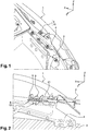
- Figures 1 and 2 a partial view of the left front part of a motor vehicle, illustrating the attachment zone of a front wing 1 and a front left optical projector 2 of the vehicle.
- This vehicle typically comprises a plastic front fender. This is mounted on the structure 3 of the vehicle prior to the passage of the structure in cataphoresis and oven.
- the wing is conventionally fixed to the structure in three attachment points: two high and low rear attachment points and a front attachment point, these points being distributed the mechanical maintenance and isostatism of the wing.
- the front fixing point essentially ensures a fixation in directions Y and Z.
- the structural element of the vehicle on which the wing 1 is fixed is typically an "awning side reinforcement" according to the terminology of the man.
- this attachment to the structure 3 is achieved by means of a wing support 4 which is a stamped piece coming from a shoe fixed or welded to a front spar of the vehicle or to the awning side reinforcement. .
- this support 4 has the general shape of a U tilted at 90 °, one of the branches of the U, located in the upper part, defines a plate on which is fixed a corresponding platen coming from the wing 1.
- first plate 5" and second plate 6 we will designate the plates of the wing and the wing support respectively by the terms “first plate 5" and second plate 6 ".
- the passage in cataphoresis and oven of the wing 1 implies an expansion of the latter which can reach 30 mm in the longitudinal direction X.
- the front part of the wing 1 is fixed to the vehicle structure by means of the fastening device according to the invention, which provides two functions according to the phases of use: in a first phase, the fastening device ensures a premaintening of the wing 1 during the phases of cataphoresis and of passage in an oven, this premaintening allowing a displacement of the front part of the wing 1 in the longitudinal direction X, so as to allow the expansion and retraction of the wing; in a second phase, the fixing device ensures a complete attachment of the wing 1 on the structure, eliminating all possible movements.
- the fixing device of the invention for securing the first plate 5 to the second plate 6 contiguous to each other is defined as follows: the first plate 5 comprises a window 7 ( Figures 3, 4 , 11-13 ).
- the second plate 6 comprises a guide light 8 ( Figures 11-15 ), placed opposite the window 7.
- the window 7 has an elongated shape extending, like the light 8 in the longitudinal direction X of the vehicle.
- the fixing device of the invention comprises a screw-nut assembly consisting of a screw 9 and a nut 10 introduced together through the window 7 and the light 8 to a stop position in which a flange 11 adjacent to the screw head bears on the first plate 5.
- the flange 11 may be directly constituted by the screw head.
- the nut 10 comprises clipping conformations 12, typically two elastically deformable tabs, located on either side of the main body of the nut 10, these fins co-operating in abutment with the second plate 6 in the vicinity of the slot 8, to prevent extraction of the screw-nut assembly.
- the screw 9 is partially screwed onto the nut 10.
- the nut 10 comprises a quarter turn system, movable under the influence of a rotation printed with the screw.
- the rotation is carried out between on the one hand an initial angular position ( figures 5 , 11, 14, 15 ) in which the nut 10 is introduced into the window 7 and the light 8, the nut 10 having guide flanks 13 fitted with corresponding edges of the window 7 and the light 8 to wedge and pre-hold the plates 5, 6 relative to each other in the transverse direction Y, while allowing relative sliding between the plates 5, 6 in the longitudinal direction X, and secondly a final angular position ( figure 13 ) in which locking flanks 14 ( Figures 9, 10 ) of the nut 10 cooperate abutting against corresponding edges of the window 7 and the slot 8 to limit the rotation of the nut 10 to a quarter of a turn.
- an initial angular position figures 5 , 11, 14, 15
- the nut 10 having guide flanks 13 fitted with corresponding edges of the window 7 and the light 8 to wedge and pre-hold the plates 5, 6 relative to each other in the transverse direction Y, while allowing relative sliding between the plates 5, 6 in the longitudinal direction X
- the nut 10 is locked in rotation when the rotation printed on the screw 9 is always in the same direction.
- the rotation of the screw 9 always in the same direction then causes the nut 10 to rise again in order to completely tighten the plates 5, 6.
- the nut 10 therefore comprises shoulders 17 ( Figures 7, 9, 10 ) whose dimensions are adjusted to pass through the window 7 and the light 8 when the screw-nut assembly is in its initial angular configuration ( figure 11 ), but whose shapes come to cooperate in contact with the second plate 6, in the vicinity of the light 8 when the screw-nut assembly is disposed in its final angular position ( figure 13 ).
- the nut 10 consists of a one-piece assembly comprising a main body having in side view the general shape of a T upside down extending in the axial direction of screwing.
- the thickness of the T is slightly less than the transverse dimensions of the window 7 and the 8.
- a clearance of the order of one to two millimeters is formed vis-à-vis the plates 5, 6 so as to pass the nut in the window 7 and the light 8.
- the main body of the nut 10 is decomposed into an upper block 15 and a lower block 16.
- the upper block 15 forms the leg of the T on which are formed the guide flanks 13 and the flanks of blockages 14. These flanks are shaped along cylindrical generatrices parallel to the axial direction of screwing.
- the lower block 16 forms the transverse branch of the T at the ends of which are located the shoulders 17.
- the clipping conformations 12 consisting of elastically deformable tabs extend from opposite faces of the lower block 16 these faces defining between them the thickness of the T.
- the lower block 16 has the general shape of an elongate parallelepiped whose length is slightly less than the length of the window 7. A clearance of the order of 1 to 2 mm is formed between the lower block 16 and the window 7 so as to facilitate its passage through it.
- the clipping conformations 12 are located in the middle of the long sides of the elongated shape of the lower block 16 ( Figures 9, 10 ).
- the lower block 16 has a tapered shape on all four sides from its edge adjacent to the upper block 15 towards its opposite free edge. This aspect is further to facilitate the passage of the lower block 16 in the window and the light.
- the upper block 15 has a general shape inscribed in a square of which two opposite sides partially marry the guide flanks 13 and two other opposite sides partially marry the locking flanks 14.
- the guide flanks 13 and the locking flanks 14 meet in the form of two opposite edges 18 (corresponding to two opposite corners of the square) and two rounded shapes 19, which allow the rotation of a quarter turn of the nut 10 between the initial and final angular positions by sliding along the longitudinal edges of the window 7 and the light 8.
- the nut 10 has a threaded central hole 20 ( Figures 9, 10 ) passing through the upper block 15 and the lower block 16 from one side, substantially in the vertical direction Z when the screw-nut assembly is in place on the vehicle.
- the motor vehicle comprising a fixing device according to the invention allows the improved fixing of an optical projector 2.
- the latter comprises in its rear part a lug 21 provided with a fusible zone 22 in case of impact ( figure 3 ).
- the latter is of conventional design and well known to those skilled in the art (weakened and frangible portion able to yield when a force exceeding a predetermined threshold is applied, here in the longitudinal direction X).
- an indexing pin cooperating directly with an orifice 23 ( figure 4 ) formed in the first plate 5, in the longitudinal extension of the window 5 towards the front of the vehicle.
- the tab 21 is also attached to the wing support 4 via a fastening screw screwed into a corresponding hole 24 ( figure 4 ), which is located between the indexing orifice 23 and the fusibility zone 22.
Description
La présente invention concerne un dispositif de fixation. Elle se rapporte plus particulièrement à un dispositif de fixation de deux éléments, apte à assurer dans une première configuration un prémaintien autorisant un coulissement relatif entre les deux éléments, et dans une seconde configuration une fixation complète des deux éléments. L'invention se rapporte également à un véhicule automobile pourvu d'un tel dispositif de fixation.The present invention relates to a fastening device. It relates more particularly to a device for fixing two elements, adapted to ensure in a first configuration premaintening allowing relative sliding between the two elements, and in a second configuration a complete fixation of the two elements. The invention also relates to a motor vehicle provided with such a fixing device.
On connaît dans l'état de la technique des dispositifs de fixation entre deux éléments permettant d'assurer dans une première configuration d'utilisation une fonction de prémaintien et dans une seconde configuration d'utilisation une fonction de fixation complète ou définitive. On connait de
Dans le secteur automobile par exemple, une aile avant en matière plastique peut être montée sur la structure du véhicule préalablement à son passage en cataphorèse et en étuve. Or le passage en étuve soumet l'aile à des températures élevées, de l'ordre de 100°C à 120°C. Cette température engendre une dilatation / déformation de l'aile plastique pouvant atteindre 30 mm suivant la direction longitudinale du véhicule. L'aile est classiquement fixée à la structure du véhicule en trois points de fixation : deux points de fixation arrière haut et bas sur un renfort de côté d'auvent et un point de fixation avant sur ce même renfort via un support d'aile. Ainsi lors du passage en étuve il est nécessaire de prévoir une possibilité de dilatation de l'aile suivant la direction longitudinale du véhicule. De façon connue, l'aile comporte une patte latérale s'étendant suivant la direction transversale vers l'intérieur du véhicule. La patte latérale prend appui verticalement sur le support d'aile solidaire de la structure du véhicule. La patte latérale s'étend suivant la direction longitudinale du véhicule et comporte une lumière s'étendant suivant cette même direction. Cette lumière est traversée par un organe de guidage traversant la lumière et clippé verticalement dans un orifice ménagé sur le renfort d'aile. L'organe de guidage est ajusté dans la lumière de sorte que la partie avant de l'aile peut coulisser par rapport à l'organe de guidage et au support d'aile suivant la dimension longitudinale du véhicule tout en assurant une indexation suivant la direction transversale. Une fois les passages en cataphorèse et en étuve réalisés, l'aile reprend sa dimension définitive en refroidissant. La fixation complète de l'aile sur le support d'aile est réalisée par un système vis-écrou qui est situé à proximité de l'organe de guidage, typiquement à l'arrière de ce dernier. La vis traverse la lumière de la patte latérale ainsi qu'un autre orifice ménagé sur le support d'aile. La vis est serrée de façon à assurer une fixation complète de l'aile sur le support d'aile.In the automotive sector for example, a plastic front wing can be mounted on the vehicle structure prior to its passage in cataphoresis and in an oven. However, the passage in an oven submits the wing to high temperatures, of the order of 100 ° C to 120 ° C. This temperature causes an expansion / deformation of the plastic wing up to 30 mm in the longitudinal direction of the vehicle. The wing is conventionally attached to the vehicle structure in three attachment points: two high and low rear attachment points on a canopy side reinforcement and a front attachment point on the same reinforcement via a wing support. Thus during the passage in an oven it is necessary to provide a possibility of expansion of the wing in the longitudinal direction of the vehicle. In known manner, the wing has a lateral lug extending in the transverse direction towards the inside of the vehicle. The lateral leg is supported vertically on the wing support secured to the vehicle structure. The side tab extends in the longitudinal direction of the vehicle and has a light extending in the same direction. This light is traversed by a guide member passing through the light and clipped vertically into an orifice formed on the wing reinforcement. The guide member is adjusted in the light so that the front portion of the wing can slide relative to the guide member and the wing support along the longitudinal dimension of the vehicle while providing indexing in the direction cross. Once the passages in cataphoresis and in oven performed, the wing takes its final dimension cooling. The complete attachment of the wing to the wing support is achieved by a screw-nut system which is located near the guide member, typically at the rear of the latter. The screw passes through the light of the side tab and another hole on the wing support. The screw is tightened so as to ensure complete attachment of the wing to the wing support.
Un tel dispositif de fixation est encombrant puisqu'il comprend un organe de guidage et un système vis-écrou dissociés et juxtaposés suivant la direction longitudinale du véhicule. En outre ces pièces multiples imposent autant de manipulations et d'opérations de mise en place.Such a fixing device is bulky since it comprises a guide member and a screw-nut system dissociated and juxtaposed in the longitudinal direction of the vehicle. In addition, these multiple pieces require as many manipulations and set-up operations.
De plus, l'organe de guidage et le système vis-écrou sont typiquement situés à proximité d'une fixation arrière fusible du projecteur. Le projecteur comprend dans sa partie arrière une patte de fixation fusible assurant la fixation par vis du projecteur sur le support d'aile, ainsi que son indexation. Cette fixation fusible permet une rupture de la fixation en cas de chocs « RCAR » correspondant à des chocs à vitesses inférieurs à 15km/h (norme répondant aux préconisations d'assureurs visant à réduire les frais de réparation). De façon connue, l'indexation suivant les directions longitudinale et transversale de la patte arrière du projecteur est assurée directement sur le support d'aile par un pion issu de la patte arrière qui coopère avec un orifice ou une encoche ménagé sur le support d'aile. L'indexation du projecteur sur le support d'aile dégrade la chaîne de cotes et engendre des dispersions géométriques qui ne permettent pas de bien maitriser les jeux et affleurements entre le projecteur et le bord d'aile, visibles depuis l'extérieur du véhicule. En outre, ces moyens de fixation et d'indexation de la patte arrière du projecteur encombrent encore davantage la zone de fixation de l'aile.In addition, the guide member and the screw-nut system are typically located near a fusible rear mounting of the projector. The projector comprises in its rear part a fusible fixing lug ensuring the fixation by screw of the projector on the wing support, and its indexing. This fusible fastener allows a rupture of the binding in the event of "RCAR" shocks corresponding to shocks with speeds lower than 15km / h (standard meeting the recommendations of insurers aiming at reducing repair costs). In known manner, the indexing along the longitudinal and transverse directions of the rear leg of the headlamp is ensured directly on the wing support by a pin coming from the rear leg which cooperates with a hole or a notch formed on the support of wing. The indexing of the projector on the wing support degrades the chain of dimensions and generates geometric dispersions that do not allow to control the clearances and outcrops between the projector and the wing edge, visible from the outside of the vehicle. In addition, these fixing means and indexing of the rear leg of the projector further encumber the wing attachment area.
L'invention a pour but de pallier tout ou partie des inconvénients précédents en proposant un dispositif de fixation qui pallie tout ou partie des inconvénients précédents en terme d'encombrement, de pluralité de pièces à monter et de défauts géométriques.The invention aims to overcome all or part of the above disadvantages by providing a fixing device that overcomes all or part of the above disadvantages in terms of space, a plurality of parts to mount and geometric defects.
A cet effet, l'invention a pour objet un dispositif de fixation d'une première platine sur un seconde platine accolées l'une contre l'autre, l'une des platines étant pourvue d'une fenêtre tandis que l'autre platine comporte une lumière de guidage placée en vis-à-vis de la fenêtre, caractérisé en ce qu'il comprend un ensemble vis-écrou, la vis et l'écrou étant introduits au travers de la fenêtre et de la lumière jusqu'à une position de butée dans laquelle une collerette adjacente à la tête de vis prend appui sur l'une des platines, tandis que l'écrou comprend des conformations de clippage coopérant en butée avec l'autre platine pour empêcher l'extraction de l'ensemble vis-écrou, l'écrou comprenant un système quart de tour, mobile sous l'influence d'une rotation imprimée à la vis, entre d'une part une position angulaire initiale dans laquelle l'écrou est introduit dans la fenêtre et la lumière, l'écrou comportant des flancs de guidage ajustés avec des bords correspondants de la fenêtre et de la lumière pour caler les platines l'une par rapport à l'autre transversalement à la direction longitudinale de la lumière tout en autorisant un coulissement relatif entre les platines dans la direction longitudinale, et d'autre part une position angulaire finale dans laquelle des flancs de blocage de l'écrou coopèrent en butée contre des bords correspondants de la fenêtre et de la lumière pour limiter la rotation de l'écrou, la vis et l'écrou étant de ce fait aptes à être serrés de façon à assurer une fixation complète entre les deux platines via des épaulements conformés sur l'écrou, lesquels sont décalés angulairement par rapport à la fenêtre et à la lumière pour coopérer en contact avec la platine adjacente.For this purpose, the invention relates to a device for fixing a first plate on a second plate contiguous to one another, one of the plates being provided with a window while the other plate comprises a guide light placed opposite the window, characterized in that it comprises a screw-nut assembly, the screw and the nut being introduced through the window and the light to a position abutment in which a flange adjacent to the screw head is supported on one of the plates, while the nut comprises clipping conformations cooperating in abutment with the other plate to prevent the extraction of the screw assembly. nut, the nut comprising a quarter-turn system, movable under the influence of a rotation printed with the screw, between on the one hand an initial angular position in which the nut is introduced into the window and the light, nut having guide flanks fitted with bor ds corresponding the window and the light to wedge the plates relative to each other transversely to the longitudinal direction of the light while allowing a relative sliding between the plates in the longitudinal direction, and secondly a final angular position in which the locking flanks of the nut cooperate abutting against corresponding edges of the window and the light to limit the rotation of the nut, the screw and the nut being thus able to be tightened so as to ensure complete fixation between the two plates via shoulders shaped on the nut, which are offset angularly with respect to the window and the light to cooperate in contact with the adjacent plate.
Ainsi le dispositif de fixation assure plusieurs fonctions :
- une fonction de prémaintien et de guidage de l'une des platines par rapport à l'autre, permettant un déplacement longitudinal entre les platines,
- une fonction de fixation complète des platines entre elles.
- a function of pre-maintenance and guiding of one of the plates relative to the other, allowing a longitudinal displacement between the plates,
- a function of complete fixing of the plates between them.
Selon d'autres caractéristiques avantageuses de l'invention :
- le bloc inférieur a une forme allant en s'évasant depuis son bord adjacent au bloc supérieur vers son bord libre opposé,
- les conformations de clippage s'étendent depuis des faces opposées du bloc inférieur ces faces définissant entre elles l'épaisseur du T.
- the lower block has a shape flaring from its edge adjacent to the upper block towards its opposite free edge,
- the clipping conformations extend from opposite faces of the lower block these faces defining between them the thickness of the T.
L'invention a également pour objet un véhicule automobile comprenant au moins une aile latérale en plastique montée sur la structure du véhicule, l'aile étant fixée dans sa partie avant à un support d'aile solidaire de la structure du véhicule, caractérisé en ce qu'il comprend un dispositif de fixation selon l'une quelconque des revendications précédentes, la première platine étant venue de matière avec l'aile tandis que la seconde platine est une partie intégrante du support d'aile.The invention also relates to a motor vehicle comprising at least one plastic lateral wing mounted on the vehicle structure, the wing being fixed in its front part to a wing support integral with the vehicle structure, characterized in that it comprises a fixing device according to any one of the preceding claims, the first plate being integral with the wing while the second plate is an integral part of the wing support.
Selon d'autres caractéristiques avantageuses de l'invention :
- la fenêtre est ménagée dans la première platine tandis que la lumière est ménagée dans la seconde platine, la longueur de la lumière étant comprise entre 40 mm et 60 mm, la longueur de la fenêtre étant comprise entre 20 et 30 mm,
- le véhicule comprend un projecteur optique comportant dans sa partie arrière une patte munie d'une zone de fusibilité en cas de choc, à l'arrière de laquelle est prévue un pion d'indexation coopérant directement avec un orifice ménagé dans la première platine, la patte étant fixée au support d'aile via une vis de fixation située entre le pion d'indexation et la zone de fusibilité,
- la première et la seconde platines s'étendent transversalement à la direction longitudinale depuis l'aile et la structure du véhicule vers l'intérieur du véhicule, la fenêtre et la lumière s'étendant de façon sensiblement parallèle à la direction longitudinale du véhicule.
- the window is formed in the first plate while the light is formed in the second plate, the length of the light being between 40 mm and 60 mm, the length of the window being between 20 and 30 mm,
- the vehicle comprises an optical projector comprising in its rear part a lug provided with a fusibility zone in the event of an impact, behind which is provided an indexing pin cooperating directly with an orifice formed in the first plate, the leg being fixed to the wing support via a fixing screw located between the indexing pin and the fusibility zone,
- the first and second plates extend transversely to the longitudinal direction from the wing and the structure of the vehicle towards the interior of the vehicle, the window and the light extending substantially parallel to the longitudinal direction of the vehicle.
L'invention sera mieux comprise à la lecture de la description suivante d'un exemple non limitatif de l'invention, et à la lumière des dessins annexés sur lesquels :
- la
figure 1 représente une vue en perspective de la zone de fixation avant d'une aile avant sur la structure d'un véhicule automobile, dans laquelle est situé un dispositif de fixation suivant l'invention, le projecteur avant n'étant pas représenté, - la
figure 2 est une vue agrandie de la zone de fixation de lafigure 1 dans laquelle se situent le dispositif de fixation de l'invention et la fixation arrière d'un projecteur optique avant du véhicule, - les
figures 3 sont des vues encore agrandies du dispositif de fixation de l'invention, avec et sans la fixation arrière du projecteur optique dans le contexte de la zone de fixation de laet 4figure 1 , - les
figures 5 à 8 sont différentes vues de côté ou en perspective du dispositif de fixation de l'invention pourvu du système complet vis-écrou, - les
figures 9 et 10 sont des vues en perspective et de dessus de l'écrou seul du dispositif selon l'invention, - les
figures 11 à 13 sont des vues de dessus illustrant différentes phases dans le montage du dispositif de fixation selon l'invention, entre les positions angulaires initiale et finale, - la
figures 14 et 15 sont des vues en perspectives du dispositif de fixation selon l'invention associé à la platine comportant une lumière de guidage, représentées respectivement avec et sans la vis.
- the
figure 1 represents a perspective view of the forward attachment zone of a front fender on the structure of a motor vehicle, in which is located a fixing device according to the invention, the front projector not being shown, - the
figure 2 is an enlarged view of the attachment area of thefigure 1 in which are located the fixing device of the invention and the rear fixing of a front optical projector of the vehicle, - the
Figures 3 and 4 are still enlarged views of the fixing device of the invention, with and without the rear fixing of the optical projector in the context of the fixing area of thefigure 1 , - the
Figures 5 to 8 are different views from the side or in perspective of the fixing device of the invention provided with the complete screw-nut system, - the
Figures 9 and 10 are views in perspective and from above of the single nut of the device according to the invention, - the
Figures 11 to 13 are views from above illustrating different phases in the mounting of the fastening device according to the invention, between the initial and final angular positions, - the
Figures 14 and 15 are perspective views of the fixing device according to the invention associated with the plate comprising a guide light, respectively represented with and without the screw.
Dans l'ensemble du texte, les directions sont indiquées en référence au repère XYZ classiquement utilisé en conception automobile, dans lequel X désigne la direction longitudinale avant-arrière du véhicule, dirigée vers l'arrière, Y la direction transversale du véhicule, dirigée vers la droite, et Z la direction verticale du véhicule dirigée vers le haut.
On a représenté aux
Le passage en cataphorèse et en étuve de l'aile 1 implique une dilatation de cette dernière qui peut atteindre 30 mm dans la direction longitudinale X. Considérant que la structure se dilate d'une façon infime en comparaison, la partie avant de l'aile 1 est fixée à la structure du véhicule par l'intermédiaire du dispositif de fixation suivant l'invention, qui assure deux fonctions suivant les phases d'utilisation : dans une première phase, le dispositif de fixation assure un prémaintien de l'aile 1 durant les phases de cataphorèse et de passage en étuve, ce prémaintien autorisant un déplacement de la partie avant de l'aile 1 suivant la direction longitudinale X, de façon à autoriser la dilatation et la rétractation de l'aile; dans une seconde phase, le dispositif de fixation assure une fixation complète de l'aile 1 sur la structure, supprimant tous les mouvements possible.Throughout the text, the directions are indicated with reference to the reference XYZ conventionally used in automotive design, wherein X designates the longitudinal direction of the front-rear of the vehicle, directed towards the rear, Y the transverse direction of the vehicle, directed towards the right, and Z the vertical direction of the vehicle directed upwards.
Representatives
The passage in cataphoresis and oven of the
Pour ce faire, le dispositif de fixation de l'invention visant à solidariser la première platine 5 sur la seconde platine 6 accolées l'une contre l'autre est défini comme suit: la première platine 5 comporte une fenêtre 7 (
En référence aux
Comme on le voit aux
En référence aux
En vue de dessus, sensiblement suivant la direction verticale Z, le bloc supérieur 15 a une forme générale inscrite dans un carré dont deux côtés opposés épousent en partie les flancs de guidage 13 et deux autres côtés opposés épousent en partie les flancs de blocage 14. Les flancs de guidage 13 et les flancs de blocage 14 se rejoignent sous la forme de deux arêtes opposées 18 (correspondant à deux angles opposés du carré) et de deux formes arrondies 19, lesquelles permettent la rotation d'un quart de tour de l'écrou 10 entre les positions angulaires initiale et finale par glissement le long des bords longitudinaux de la fenêtre 7 et de la lumière 8.
L'écrou 10 comporte un trou central 20 fileté (
With reference to
As we see in
With reference to
In plan view, substantially in the vertical direction Z, the
The
En référence aux
- l'ensemble vis-
écrou L'écrou 10 est introduit dans la fenêtre 7 et la lumière 8 de sorte que le bloc inférieur soit situé en dessous des platines. Les conformations de clippage 12 qui ont été déformées en traversant la fenêtre et la platine sont libérées de toute contrainte et reprennent leur forme initiale, prenant appui sur les bords de la lumière 8.L'écrou 10 ne peut plus être retiré intempestivement. La vis 9 et l'écrou 10 sont alors dans la position angulaire initiale. - les platines peuvent être déplacées l'une par rapport à l'autre suivant la direction longitudinale X du véhicule, les flancs de guidage 13 ménagés sur le
bloc supérieur 15 coopérant en contact ou à distance des bords périphériques de la fenêtre et de la lumière. Ces flancs positionnent les platines l'une par rapport à l'autre suivant la direction transversale Y.La première platine 5 venue de l'aile 1 peut être déplacée relativement à la seconde platine 6 (fixe) solidaire de la structure. Ce déplacement est provoqué vers l'avant (lors de la dilatation de l'aile 1 due au passage en étuve) puis vers l'arrière (l'aile 1 reprenant sa forme initiale en se rétractant par le refroidissement). - l'ensemble vis-écrou est installé dans sa position de fixation complète. La vis est tournée d'un quart de tour dans le sens horaire (
figure 12 ). La vis 9entraîne l'écrou 10 en rotation dans le sens horaire jusqu'à une position de butée dans laquelle les flancs de blocage 14 coopèrent en contact avec les bords longitudinaux de la fenêtre 7 et/ou de la lumière 8. La vis est ensuite vissée, toujours en tournant dans le sens horaire faisant remonter l'écrou 10 bloqué en rotation. Les platines 5et 6 sont ainsi serrées l'une contre l'autre pour assurer leur fixation définitive. Bien entendu, le dispositif de fixation est démontable, les opérations ci-dessus devant être réalisées dans l'ordre inverse.
- the screw-
nut assembly plates 5, 6: thenut 10 is positioned in a lifetime screw of thewindow 7 in the same longitudinal direction as the latter. Thenut 10 is introduced into thewindow 7 and thelight 8 so that the lower block is located below the plates. The clipping conformations 12 which have been deformed while passing through the window and the plate are released from all restraint and return to their original shape, resting on the edges of thelight 8. Thenut 10 can no longer be removed untimely. Thescrew 9 and thenut 10 are then in the initial angular position. - the plates can be moved relative to each other in the longitudinal direction X of the vehicle, the guide flanks 13 formed on the
upper block 15 cooperating in contact or at a distance from the peripheral edges of the window and the light. These flanks position the plates relative to each other in the transverse direction Y. Thefirst plate 5 coming from thewing 1 can be moved relative to the second plate 6 (fixed) integral with the structure. This displacement is caused to the front (during the expansion of thewing 1 due to the passage in an oven) and then to the rear (thewing 1 returning to its original shape by retracting by cooling). - the screw-nut assembly is installed in its complete fixing position. The screw is turned a quarter of a turn clockwise (
figure 12 ). Thescrew 9 drives thenut 10 in rotation clockwise to an abutment position in which the locking flanks 14 cooperate in contact with the longitudinal edges of thewindow 7 and / or thelight 8. The screw is then screwed, always turning clockwise making up thenut 10 locked in rotation. Theplates
Avantageusement, le véhicule automobile comprenant un dispositif de fixation selon l'invention permet la fixation améliorée d'un projecteur optique 2. Ce dernier comporte dans sa partie arrière une patte 21 munie d'une zone de fusibilité 22 en cas de choc (
Claims (7)
- Device for fastening a first plate (5) on to a second plate (6) attached to one another, one of the plates being provided with a window (7) while the other plate includes a guiding opening (8) placed facing the window (7), comprising a screw-nut assembly, the screw (9) and the nut (10) being introduced through the window (7) and the opening (8) to a position of abutment in which a flange (11) adjacent to the screw head (9) bears on one of the plates, while the nut (10) comprises clipping conformations (12) cooperating by abutment with the other plate to prevent the extraction of the screw-nut assembly, the nut (10) comprising a quarter-turn system, mobile under the influence of a rotation imparted on the screw (9), between, on the one hand, an initial angular position in which the nut (10) is introduced into the window (7) and the opening (8), the nut (10) comprising guiding flanks (13) fitted with corresponding edges of the window (7) and of the opening (8) to align the plates (5; 6) relative to one another transversely in the longitudinal direction of the opening (8) while allowing relative sliding between the plates (5; 6) in the longitudinal direction, and, on the other hand, a final angular position in which the immobilizing flanks (14) of the nut (10) cooperate by abutment against corresponding edges of the window (7) and of the opening (8) to limit the rotation of the nut (10), the screw (9) and the nut (10) being thereby able to be tightened so as to ensure a complete fastening between the two plates (5; 6) via shoulders (17) conformed on the nut (10), which are angularly offset in relation to the window (7) and to the opening (8) to cooperate in contact with the adjacent plate (6), characterized in that the nut (10) consists of a one-piece assembly comprising a main body having, in side view, the general form of an upside-down T extending in the axial direction of screwing, the thickness of the T being less than the transverse dimensions of the window (7) and of the opening (8), the main body being subdivided, on the one hand, into a top block (15) forming the leg of the T on which the guiding flanks (13) and the immobilizing flanks (14) are formed along cylindrical generatrices parallel to the axial direction of screwing, and, on the other hand, into a bottom block (16) forming the transverse branch of the T at the ends of which the shoulders (17) are situated and in that the top block (15) has a general form inscribed in a square whose two opposite sides mould to the guiding flanks (13) and two other opposite sides mould to the immobilizing flanks (14), the guiding flanks (13) and the immobilizing flanks (14) meeting in the form of two opposing edges (18) and two rounded forms (19) allowing the rotation by a quarter-turn of the nut (10) between the initial and final angular positions.
- Fastening device according to Claim 1, characterized in that the bottom block (16) has a streamlined form from its edge adjacent to the top block (15) to its opposing free end.
- Fastening device according to Claim 2, characterized in that the clipping conformations (12) extend from the opposing faces of the bottom block (16), these faces defining between them the thickness of the tee.
- Motor vehicle comprising at least one lateral wing (1) made of plastic mounted on the structure of the vehicle, the wing (1) being fastened in its front part to a wing support (4) secured to the structure of the vehicle, characterized in that it comprises a fastening device according to any one of the preceding claims, the first plate (5) being made of a single piece with the wing (1) whereas the second plate (6) is an integral part of the wing support (4).
- Motor vehicle according to Claim 4, characterized in that the window (7) is formed in the first plate (5) whereas the opening (8) is formed in the second plate (6), the length of the opening (8) lying between 40 mm and 60 mm, the length of the window (7) lying between 20 and 30 mm.
- Motor vehicle according to Claim 5, characterized in that it comprises a lamp (2) comprising, in its rear part, a tab (21) provided with a zone of fusibility (22) in case of impact, behind which there is provided an indexing pin cooperating directly with an orifice (23) formed in the first plate (5), the tab (21) being fixed to the wing support (4) via a fastening screw situated between the indexing pin and the zone of fusibility (22).
- Motor vehicle according to any one of Claims 4 to 6, characterized in that the first (5) and the second (6) plates extend transversely in the longitudinal direction (X) from the wing (1) and the structure of the vehicle towards the interior of the vehicle, the window (7) and the opening (8) extending substantially parallel to the longitudinal direction (X) of the vehicle.
Applications Claiming Priority (2)
| Application Number | Priority Date | Filing Date | Title |
|---|---|---|---|
| FR1358299A FR3010036B1 (en) | 2013-08-30 | 2013-08-30 | FIXING DEVICE WITH TWO MODES OF USE AND MOTOR VEHICLE COMPRISING SUCH A DEVICE |
| PCT/FR2014/051669 WO2015028729A1 (en) | 2013-08-30 | 2014-06-30 | Fastening device with two use modes and motor vehicle comprising such a device |
Publications (2)
| Publication Number | Publication Date |
|---|---|
| EP3038882A1 EP3038882A1 (en) | 2016-07-06 |
| EP3038882B1 true EP3038882B1 (en) | 2018-02-14 |
Family
ID=49876787
Family Applications (1)
| Application Number | Title | Priority Date | Filing Date |
|---|---|---|---|
| EP14747071.0A Active EP3038882B1 (en) | 2013-08-30 | 2014-06-30 | Fastening device with two use modes and motor vehicle comprising such a device |
Country Status (3)
| Country | Link |
|---|---|
| EP (1) | EP3038882B1 (en) |
| FR (1) | FR3010036B1 (en) |
| WO (1) | WO2015028729A1 (en) |
Families Citing this family (1)
| Publication number | Priority date | Publication date | Assignee | Title |
|---|---|---|---|---|
| CN114132390A (en) * | 2022-01-11 | 2022-03-04 | 徐州徐工矿业机械有限公司 | Mining dump truck cargo compartment fender fixing device and mining dump truck |
Family Cites Families (3)
| Publication number | Priority date | Publication date | Assignee | Title |
|---|---|---|---|---|
| US5028190A (en) * | 1990-09-17 | 1991-07-02 | Chrysler Corporation | Snap-in floating screw-anchor |
| DE19809935C2 (en) * | 1998-03-07 | 2002-11-28 | Rehau Ag & Co | Method of connecting a bumper |
| FR2947314B1 (en) * | 2009-06-26 | 2011-06-17 | Raymond A & Cie | PLASTIC NUT FASTENING DEVICE |
-
2013
- 2013-08-30 FR FR1358299A patent/FR3010036B1/en not_active Expired - Fee Related
-
2014
- 2014-06-30 WO PCT/FR2014/051669 patent/WO2015028729A1/en active Application Filing
- 2014-06-30 EP EP14747071.0A patent/EP3038882B1/en active Active
Also Published As
| Publication number | Publication date |
|---|---|
| EP3038882A1 (en) | 2016-07-06 |
| FR3010036B1 (en) | 2017-01-13 |
| FR3010036A1 (en) | 2015-03-06 |
| WO2015028729A1 (en) | 2015-03-05 |
Similar Documents
| Publication | Publication Date | Title |
|---|---|---|
| EP1604886B1 (en) | Assembly of a chassis of a motor vehicle | |
| EP2914476B1 (en) | Device for attaching two structural parts to each other, comprising a floating positioning element | |
| EP3149433B1 (en) | Arrangement for mounting a functional device such as a camera on a body part of a car | |
| EP3038882B1 (en) | Fastening device with two use modes and motor vehicle comprising such a device | |
| EP2062804B1 (en) | Device and method for attaching a wing assembly to an automobile body shell wall | |
| EP3765337B1 (en) | Sensor support for a vehicle and method of mounting | |
| WO2017006011A1 (en) | Motor vehicle front headlamp equipped with a casing comprising a lower anchoring element | |
| EP2655167B1 (en) | Device for strengthening the wing of a vehicle on a bodywork structure | |
| EP3050758B1 (en) | Structural subassembly of a motor vehicle and method for mounting said subassembly | |
| EP3380366A1 (en) | Device for mounting a radar for a motor vehicle | |
| EP3381747A1 (en) | Device for attaching a headlight to a vehicle | |
| FR2991962A1 (en) | Device for adjusting position of door module of car before final fixing of module in door liner, has set of actuators arranged on module, where each actuator comprises series of grooves engageable between grooves of other set of actuators | |
| EP3350064B1 (en) | Supporting structure for a front-end module of a motor vehicle and front-end module comprising said supporting structure | |
| EP0459849B1 (en) | Adjustable mounting for motor vehicule bumper | |
| EP3409567B1 (en) | Support device for a dashboard of a motor vehicle | |
| EP1934081B1 (en) | Cover for a steering column | |
| FR3110509A1 (en) | Chassis of a motor vehicle equipped with an audible warning device attached to a support mounted on the tilting chassis at a predefined force threshold. | |
| EP2045171B1 (en) | Front module for motor vehicles and related assembling method | |
| FR2931408A1 (en) | Rear signal light fixing system for housing of body of motor vehicle, has cut flexible tongue extended in plane of opening from edge of opening, and fixation unit with wedge shape part for being supported at free end of tongue | |
| FR2758509A1 (en) | Fixing for bumper to chassis of vehicle | |
| EP2139725B1 (en) | Trimming panel arrangement for the door of an automobile | |
| FR3139774A1 (en) | Side trim for the bumper of a motor vehicle, bumper of a motor vehicle comprising such a side trim and motor vehicle comprising such a bumper | |
| EP2095995A1 (en) | Front assembly of an automobile comprising a front headlight | |
| FR2986758A1 (en) | Mounting bracket for fixing roof rail on roof of car, has indexing finger comprising plastic external part, which contacts with side of opening indexing on periphery of roof when lower surface of bracket is arranged against roof | |
| WO2007026076A1 (en) | For ventilation crossmember for the instrument board of a motor vehicle |
Legal Events
| Date | Code | Title | Description |
|---|---|---|---|
| PUAI | Public reference made under article 153(3) epc to a published international application that has entered the european phase |
Free format text: ORIGINAL CODE: 0009012 |
|
| 17P | Request for examination filed |
Effective date: 20160215 |
|
| AK | Designated contracting states |
Kind code of ref document: A1 Designated state(s): AL AT BE BG CH CY CZ DE DK EE ES FI FR GB GR HR HU IE IS IT LI LT LU LV MC MK MT NL NO PL PT RO RS SE SI SK SM TR |
|
| AX | Request for extension of the european patent |
Extension state: BA ME |
|
| DAX | Request for extension of the european patent (deleted) | ||
| GRAP | Despatch of communication of intention to grant a patent |
Free format text: ORIGINAL CODE: EPIDOSNIGR1 |
|
| INTG | Intention to grant announced |
Effective date: 20170825 |
|
| GRAS | Grant fee paid |
Free format text: ORIGINAL CODE: EPIDOSNIGR3 |
|
| GRAA | (expected) grant |
Free format text: ORIGINAL CODE: 0009210 |
|
| AK | Designated contracting states |
Kind code of ref document: B1 Designated state(s): AL AT BE BG CH CY CZ DE DK EE ES FI FR GB GR HR HU IE IS IT LI LT LU LV MC MK MT NL NO PL PT RO RS SE SI SK SM TR |
|
| REG | Reference to a national code |
Ref country code: GB Ref legal event code: FG4D Free format text: NOT ENGLISH |
|
| REG | Reference to a national code |
Ref country code: CH Ref legal event code: EP |
|
| REG | Reference to a national code |
Ref country code: IE Ref legal event code: FG4D Free format text: LANGUAGE OF EP DOCUMENT: FRENCH |
|
| REG | Reference to a national code |
Ref country code: DE Ref legal event code: R096 Ref document number: 602014020958 Country of ref document: DE Ref country code: AT Ref legal event code: REF Ref document number: 969661 Country of ref document: AT Kind code of ref document: T Effective date: 20180315 |
|
| REG | Reference to a national code |
Ref country code: NL Ref legal event code: MP Effective date: 20180214 Ref country code: FR Ref legal event code: PLFP Year of fee payment: 5 |
|
| REG | Reference to a national code |
Ref country code: AT Ref legal event code: MK05 Ref document number: 969661 Country of ref document: AT Kind code of ref document: T Effective date: 20180214 |
|
| PG25 | Lapsed in a contracting state [announced via postgrant information from national office to epo] |
Ref country code: NO Free format text: LAPSE BECAUSE OF FAILURE TO SUBMIT A TRANSLATION OF THE DESCRIPTION OR TO PAY THE FEE WITHIN THE PRESCRIBED TIME-LIMIT Effective date: 20180514 Ref country code: FI Free format text: LAPSE BECAUSE OF FAILURE TO SUBMIT A TRANSLATION OF THE DESCRIPTION OR TO PAY THE FEE WITHIN THE PRESCRIBED TIME-LIMIT Effective date: 20180214 Ref country code: CY Free format text: LAPSE BECAUSE OF FAILURE TO SUBMIT A TRANSLATION OF THE DESCRIPTION OR TO PAY THE FEE WITHIN THE PRESCRIBED TIME-LIMIT Effective date: 20180214 Ref country code: LT Free format text: LAPSE BECAUSE OF FAILURE TO SUBMIT A TRANSLATION OF THE DESCRIPTION OR TO PAY THE FEE WITHIN THE PRESCRIBED TIME-LIMIT Effective date: 20180214 Ref country code: HR Free format text: LAPSE BECAUSE OF FAILURE TO SUBMIT A TRANSLATION OF THE DESCRIPTION OR TO PAY THE FEE WITHIN THE PRESCRIBED TIME-LIMIT Effective date: 20180214 Ref country code: ES Free format text: LAPSE BECAUSE OF FAILURE TO SUBMIT A TRANSLATION OF THE DESCRIPTION OR TO PAY THE FEE WITHIN THE PRESCRIBED TIME-LIMIT Effective date: 20180214 Ref country code: NL Free format text: LAPSE BECAUSE OF FAILURE TO SUBMIT A TRANSLATION OF THE DESCRIPTION OR TO PAY THE FEE WITHIN THE PRESCRIBED TIME-LIMIT Effective date: 20180214 |
|
| PG25 | Lapsed in a contracting state [announced via postgrant information from national office to epo] |
Ref country code: GR Free format text: LAPSE BECAUSE OF FAILURE TO SUBMIT A TRANSLATION OF THE DESCRIPTION OR TO PAY THE FEE WITHIN THE PRESCRIBED TIME-LIMIT Effective date: 20180515 Ref country code: LV Free format text: LAPSE BECAUSE OF FAILURE TO SUBMIT A TRANSLATION OF THE DESCRIPTION OR TO PAY THE FEE WITHIN THE PRESCRIBED TIME-LIMIT Effective date: 20180214 Ref country code: BG Free format text: LAPSE BECAUSE OF FAILURE TO SUBMIT A TRANSLATION OF THE DESCRIPTION OR TO PAY THE FEE WITHIN THE PRESCRIBED TIME-LIMIT Effective date: 20180514 Ref country code: SE Free format text: LAPSE BECAUSE OF FAILURE TO SUBMIT A TRANSLATION OF THE DESCRIPTION OR TO PAY THE FEE WITHIN THE PRESCRIBED TIME-LIMIT Effective date: 20180214 Ref country code: RS Free format text: LAPSE BECAUSE OF FAILURE TO SUBMIT A TRANSLATION OF THE DESCRIPTION OR TO PAY THE FEE WITHIN THE PRESCRIBED TIME-LIMIT Effective date: 20180214 Ref country code: AT Free format text: LAPSE BECAUSE OF FAILURE TO SUBMIT A TRANSLATION OF THE DESCRIPTION OR TO PAY THE FEE WITHIN THE PRESCRIBED TIME-LIMIT Effective date: 20180214 |
|
| PG25 | Lapsed in a contracting state [announced via postgrant information from national office to epo] |
Ref country code: MT Free format text: LAPSE BECAUSE OF FAILURE TO SUBMIT A TRANSLATION OF THE DESCRIPTION OR TO PAY THE FEE WITHIN THE PRESCRIBED TIME-LIMIT Effective date: 20180214 |
|
| PG25 | Lapsed in a contracting state [announced via postgrant information from national office to epo] |
Ref country code: RO Free format text: LAPSE BECAUSE OF FAILURE TO SUBMIT A TRANSLATION OF THE DESCRIPTION OR TO PAY THE FEE WITHIN THE PRESCRIBED TIME-LIMIT Effective date: 20180214 Ref country code: IT Free format text: LAPSE BECAUSE OF FAILURE TO SUBMIT A TRANSLATION OF THE DESCRIPTION OR TO PAY THE FEE WITHIN THE PRESCRIBED TIME-LIMIT Effective date: 20180214 Ref country code: EE Free format text: LAPSE BECAUSE OF FAILURE TO SUBMIT A TRANSLATION OF THE DESCRIPTION OR TO PAY THE FEE WITHIN THE PRESCRIBED TIME-LIMIT Effective date: 20180214 Ref country code: AL Free format text: LAPSE BECAUSE OF FAILURE TO SUBMIT A TRANSLATION OF THE DESCRIPTION OR TO PAY THE FEE WITHIN THE PRESCRIBED TIME-LIMIT Effective date: 20180214 Ref country code: PL Free format text: LAPSE BECAUSE OF FAILURE TO SUBMIT A TRANSLATION OF THE DESCRIPTION OR TO PAY THE FEE WITHIN THE PRESCRIBED TIME-LIMIT Effective date: 20180214 |
|
| REG | Reference to a national code |
Ref country code: DE Ref legal event code: R097 Ref document number: 602014020958 Country of ref document: DE |
|
| PG25 | Lapsed in a contracting state [announced via postgrant information from national office to epo] |
Ref country code: DK Free format text: LAPSE BECAUSE OF FAILURE TO SUBMIT A TRANSLATION OF THE DESCRIPTION OR TO PAY THE FEE WITHIN THE PRESCRIBED TIME-LIMIT Effective date: 20180214 Ref country code: SK Free format text: LAPSE BECAUSE OF FAILURE TO SUBMIT A TRANSLATION OF THE DESCRIPTION OR TO PAY THE FEE WITHIN THE PRESCRIBED TIME-LIMIT Effective date: 20180214 Ref country code: CZ Free format text: LAPSE BECAUSE OF FAILURE TO SUBMIT A TRANSLATION OF THE DESCRIPTION OR TO PAY THE FEE WITHIN THE PRESCRIBED TIME-LIMIT Effective date: 20180214 Ref country code: SM Free format text: LAPSE BECAUSE OF FAILURE TO SUBMIT A TRANSLATION OF THE DESCRIPTION OR TO PAY THE FEE WITHIN THE PRESCRIBED TIME-LIMIT Effective date: 20180214 |
|
| PLBE | No opposition filed within time limit |
Free format text: ORIGINAL CODE: 0009261 |
|
| STAA | Information on the status of an ep patent application or granted ep patent |
Free format text: STATUS: NO OPPOSITION FILED WITHIN TIME LIMIT |
|
| 26N | No opposition filed |
Effective date: 20181115 |
|
| REG | Reference to a national code |
Ref country code: CH Ref legal event code: PL |
|
| GBPC | Gb: european patent ceased through non-payment of renewal fee |
Effective date: 20180630 |
|
| PG25 | Lapsed in a contracting state [announced via postgrant information from national office to epo] |
Ref country code: SI Free format text: LAPSE BECAUSE OF FAILURE TO SUBMIT A TRANSLATION OF THE DESCRIPTION OR TO PAY THE FEE WITHIN THE PRESCRIBED TIME-LIMIT Effective date: 20180214 |
|
| REG | Reference to a national code |
Ref country code: BE Ref legal event code: MM Effective date: 20180630 |
|
| PG25 | Lapsed in a contracting state [announced via postgrant information from national office to epo] |
Ref country code: MC Free format text: LAPSE BECAUSE OF FAILURE TO SUBMIT A TRANSLATION OF THE DESCRIPTION OR TO PAY THE FEE WITHIN THE PRESCRIBED TIME-LIMIT Effective date: 20180214 Ref country code: LU Free format text: LAPSE BECAUSE OF NON-PAYMENT OF DUE FEES Effective date: 20180630 |
|
| REG | Reference to a national code |
Ref country code: IE Ref legal event code: MM4A |
|
| PG25 | Lapsed in a contracting state [announced via postgrant information from national office to epo] |
Ref country code: GB Free format text: LAPSE BECAUSE OF NON-PAYMENT OF DUE FEES Effective date: 20180630 Ref country code: IE Free format text: LAPSE BECAUSE OF NON-PAYMENT OF DUE FEES Effective date: 20180630 Ref country code: LI Free format text: LAPSE BECAUSE OF NON-PAYMENT OF DUE FEES Effective date: 20180630 Ref country code: CH Free format text: LAPSE BECAUSE OF NON-PAYMENT OF DUE FEES Effective date: 20180630 |
|
| PG25 | Lapsed in a contracting state [announced via postgrant information from national office to epo] |
Ref country code: BE Free format text: LAPSE BECAUSE OF NON-PAYMENT OF DUE FEES Effective date: 20180630 |
|
| PG25 | Lapsed in a contracting state [announced via postgrant information from national office to epo] |
Ref country code: TR Free format text: LAPSE BECAUSE OF FAILURE TO SUBMIT A TRANSLATION OF THE DESCRIPTION OR TO PAY THE FEE WITHIN THE PRESCRIBED TIME-LIMIT Effective date: 20180214 |
|
| PG25 | Lapsed in a contracting state [announced via postgrant information from national office to epo] |
Ref country code: PT Free format text: LAPSE BECAUSE OF FAILURE TO SUBMIT A TRANSLATION OF THE DESCRIPTION OR TO PAY THE FEE WITHIN THE PRESCRIBED TIME-LIMIT Effective date: 20180214 |
|
| PG25 | Lapsed in a contracting state [announced via postgrant information from national office to epo] |
Ref country code: HU Free format text: LAPSE BECAUSE OF FAILURE TO SUBMIT A TRANSLATION OF THE DESCRIPTION OR TO PAY THE FEE WITHIN THE PRESCRIBED TIME-LIMIT; INVALID AB INITIO Effective date: 20140630 Ref country code: MK Free format text: LAPSE BECAUSE OF NON-PAYMENT OF DUE FEES Effective date: 20180214 |
|
| PG25 | Lapsed in a contracting state [announced via postgrant information from national office to epo] |
Ref country code: IS Free format text: LAPSE BECAUSE OF FAILURE TO SUBMIT A TRANSLATION OF THE DESCRIPTION OR TO PAY THE FEE WITHIN THE PRESCRIBED TIME-LIMIT Effective date: 20180614 |
|
| P01 | Opt-out of the competence of the unified patent court (upc) registered |
Effective date: 20230608 |
|
| PGFP | Annual fee paid to national office [announced via postgrant information from national office to epo] |
Ref country code: FR Payment date: 20230628 Year of fee payment: 10 Ref country code: DE Payment date: 20230620 Year of fee payment: 10 |