EP0799758B1 - Einrichtung zur gleitenden Befestigung eines Plastik-Kotflügels - Google Patents
Einrichtung zur gleitenden Befestigung eines Plastik-Kotflügels Download PDFInfo
- Publication number
- EP0799758B1 EP0799758B1 EP19970400713 EP97400713A EP0799758B1 EP 0799758 B1 EP0799758 B1 EP 0799758B1 EP 19970400713 EP19970400713 EP 19970400713 EP 97400713 A EP97400713 A EP 97400713A EP 0799758 B1 EP0799758 B1 EP 0799758B1
- Authority
- EP
- European Patent Office
- Prior art keywords
- slot
- clearance
- fastening
- plastic
- plate
- Prior art date
- Legal status (The legal status is an assumption and is not a legal conclusion. Google has not performed a legal analysis and makes no representation as to the accuracy of the status listed.)
- Expired - Lifetime
Links
Images

Classifications
-
- B—PERFORMING OPERATIONS; TRANSPORTING
- B62—LAND VEHICLES FOR TRAVELLING OTHERWISE THAN ON RAILS
- B62D—MOTOR VEHICLES; TRAILERS
- B62D29/00—Superstructures, understructures, or sub-units thereof, characterised by the material thereof
- B62D29/04—Superstructures, understructures, or sub-units thereof, characterised by the material thereof predominantly of synthetic material
- B62D29/048—Connections therefor, e.g. joints
Definitions
- the invention relates to a device for fixing a plastic element of bodywork, in particular a plastic wing of a motor vehicle on a metal support.
- the invention relates more particularly to a device for fixing a plastic bodywork element on a metal support, the coefficient of expansion is lower than that of said plastic element.
- the publication FR-A-2720794 describes a device for retaining an element body plastic on a metal support in which a staple for fixing said plastic element to the support, the coefficient of expansion is less than that of the plastic element, consists in particular by a fixing base, the fixing base carrying perpendicularly support tabs on the plastic element, said tabs being integral with a spacer provided with a through hole a fixing screw.
- a device is only justified when the attachment takes place on a part of the wing with a geometric configuration very special.
- temperature variations cause a additional shrinkage of the plastic below the initial dimensions of the wing, withdrawal which occurs only after cooling, while the wing is again locked longitudinally on the clip.
- This withdrawal causes, in the case of a front wing, a separation of the end rear of said wing relative to the front end of the front door, causing an unsightly increase in the play of appearance existing between the wing and the door.
- the invention aims to overcome this drawback.
- the invention relates to a device for fixing a plastic element of bodywork on a metal support whose coefficient of expansion is lower than that of said plastic element, device of the type comprising a fixing element which is fixed on the metal support through a longitudinal light of the plastic element, characterized in that said fastening element is mounted in longitudinal translation in said light and cooperates with elastic means providing the recall of the fastener in an equilibrium position within the lumen.
- the fixing device thus defined makes it possible to take into account the possible deformations of the plastic element while providing a precise positioning of said plastic element on the metal support.
- the first travel is different from the second travel. This feature allows you to take take into account that the variations resulting from the expansion and those resulting from the withdrawal are of different amplitude.
- the fixing element includes keying means for positioning it on the plastic element. This characteristic makes it possible to avoid inversion, moment of assembly, of the fixing element, permutation which would cause a permutation between the two deflections of different amplitude.
- the fixing element is consisting of a plate having on its underside a pad longitudinal of lower width and sliding inside the light, said plate being pierced, perpendicular to its plane, by a hole of fixation.
- the elastic means are constituted by first and second elastic blades fixed on the skate, the first blade extending from the rear part of the skate to the first end of the light, thus defining the first travel, the second blade extending from the front part of the skate to the second end of the light, defining the second travel.
- the polarizing means include a first tab emerging laterally from one side of the pad, spaced from the bottom surface of the pad by a distance slightly greater than the thickness of the corresponding edge of the light, edge which includes a cutout for introducing said tongue.
- the polarizing means include two additional tabs on the side opposite the one with the first tab, spaced from the bottom surface of the insert a distance slightly greater than the thickness of the edge light correspondent. These tabs are used to secure the fixing device on the plastic wing to be fixed, prior to its mounting on the metal support, which facilitates handling.
- the fixing element thus defined is particularly simple and not very expensive to manufacture. In particular, it can be made of plastic and be molded in one piece with the elastic blades.
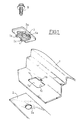
- Figure 1 shows schematically the mounting of a plastic wing 1 on a support metal 2 using the fixing device according to the invention.
- This device comprises a fixing element which is fixed on the support metallic 2 through a longitudinal light practiced in the wing plastic 1.
- the element of fixing consists of a plate 3 having on its underside a longitudinal shoe 4 of smaller width and sliding inside the longitudinal light 1a, said plate 3 being pierced, perpendicular to its plane, by a fixing hole 3a opening at through the longitudinal shoe 4.
- the longitudinal light has a rectangular shape slightly wider than the shoe 4 but longer.
- the plate 3 has a tongue 5a emerging laterally from one side of pad 4, spaced from the surface lower 3b of the wafer 3 by a distance slightly greater than the thickness of the corresponding edge of the light la, edge which comprises a cutout 1b for introducing said tongue 5a.
- the plate 3 has two additional tabs 5b, 5c arranged on the side of the pad 4 opposite to that carrying the first tab 5a, separated from the lower surface 3b of the wafer 3 from a distance slightly greater than the thickness of the corresponding edge of light la.
- the mounting is carried out as follows: the plate 3 is threaded, by its side comprising two tabs 5b, 5c, in the light 1a, on the side opposite the cut 1b, the two tabs 5b, 5c being slid under the wing surface 1.
- the assembly continues by introducing the tongue 5a in cutout 1b then by sliding the plate 3 longitudinally so as to bring the tongue 5a below the lower surface 3b in a position offset from cutout 1b, as it is shown in section in Figure 3.
- the plate 3 is then held on the wing which is blocked between the tongues 5a, 5b, 5c and the surface lower 3b of said wafer.
- the wing 1 thus positioned is held perpendicularly at the plane of the plate 3 while being able to slide according to its dimension longitudinal.
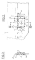
- the plate 3 comprises a first 7 and a second 8 elastic blades, for example obtained by molding with the pad 4 and the plate 3, as it is shown in Figure 4.
- the first blade 7 arises at a end of skate 4 opposite the first end 1d of the light la and extends to said first end 1d.
- This first blade 7 thus defines a first clearance D1.
- the second blade 8 takes birth at the other end of skate 4 to extend until the second end 1c of the light 1a and thus defines a second clearance D2.
- the wing 1 will expand, mainly according to its longitudinal dimension.
- the wing shown on Figure 2 corresponds to a front wing of the vehicle. As such, it is also attached to the front door which is not shown on the Figure 2 but whose location corresponds to the right of wing 1.
- the expansion will result in a translation to the left, of wing 1 and as a result of the light la, with respect to the metal support 2 and therefore to the plate 3 attached to it.
- the force exerted by the expansion being greater than that exerted by the blade 7, the 1d end of the light goes approach the end opposite the shoe 4.
- the travel D1 is obviously chosen according to the expected expansion.
- wing 1 and with it, its light gradually go move to the right to return to their starting position shown in Figure 2.
- the plastic constituting the wing 1 undergoes an additional withdrawal beyond its starting position.
- the lc end light will therefore move to the right in Figure 2, compressing the blade 8.
- the travel D2 is chosen so as to allow the removal of wing 1.
- the D1 travel is greater than D2 travel.
- the elastic return forces of the blades 7 and 8 are determined to be sufficient to ensure the positioning of the plate 3 within the lumen so as to maintain the deflections D1 and D2 chosen while not opposing the free expansion and free removal of the wing 1.
Landscapes
- Engineering & Computer Science (AREA)
- Architecture (AREA)
- Structural Engineering (AREA)
- Chemical & Material Sciences (AREA)
- Combustion & Propulsion (AREA)
- Transportation (AREA)
- Mechanical Engineering (AREA)
- Connection Of Plates (AREA)
- Body Structure For Vehicles (AREA)
Claims (7)
- Einrichtung zur Befestigung eines Plastik-Karosserieelementes (1) auf einem metallischen Träger (2), dessen Ausdehnungskoeffizient niedriger als derjenige des Plastikelementes (1) ist, wobei die Einrichtung ein Befestigungselement (3, 4) aufweist, das auf dem metallischen Träger (2) durch einen longitudinalen Durchbruch (1a) des Plastikelementes hindurch befestigt wird, wobei das Befestigungselement (3, 4) in longitudinaler Richtung in dem Durchbruch (1a) montiert ist und mit elastischen Einrichtungen (7, 8) zusammenarbeitet, dadurch gekennzeichnet, dass die elastischen Einrichtungen die Rückwärtsbewegung des Befestigungselmentes (3, 4) in eine Gleichgewichtslage sichern, derart, dass der Federweg des Befestigungselementes (3, 4) in dem Durchbruch (1a) des Plastikelementes (1) um die Gleichgewichtslage aufgeteilt ist:in einen ersten Federweg (D1), der durch den Raum zwischen einem ersten Rand (1d) des Durchbruchs (1a) und dem gegenüber liegenden Rand des Befestigungselementes (3, 4) definiert ist, wobei dieser Federweg der Ausdehnung des Plastikelementes (1) entspricht, undin einen zweiten Federweg (D2), der durch den Raum zwischen dem zweiten Rand (1c) des Durchbruches (1a) und dem gegenüberliegenden Rand des Befestigungselementes (3, 4) definiert ist, wobei dieser Federweg der Rückwärtsbewegung des gleichen Plastikelementes (1) entspricht.
- Befestigungseinrichtung nach Anspruch 1, dadurch gekennzeichnet, dass der erste Federweg (D1) unterschiedlich zu dem zweiten Federweg (D2) ist.
- Befestigungseinrichtung nach einem der Ansprüche 1 bis 2, dadurch gekennzeichnet, dass das Befestigungselement (3, 4) Zuordnungseinrichtungen (5a, 5b, 5c) zur passgenauen Positionierung auf dem Plastikelement (1) aufweist.
- Befestigungseinrichtung nach Anspruch 3, dadurch gekennzeichnet, dass das Befestigungselement durch eine Platte (3) gebildet ist, die auf ihrer unteren Fläche (3b) eine longitudinale Kufe (4) mit einer geringeren Breite aufweist, die in dem Inneren des Durchbruches (1a) gleitet, wobei die Platte (3) senkrecht zu ihrer Fläche von einem Befestigungsloch (3a) durchdrungen ist.
- Befestigungseinrichtung nach einem der vorhergehenden Ansprüche, dadurch gekennzeichnet, dass die elastischen Einrichtungen durch eine erste und eine zweite elastische Lamelle (7, 8) gebildet sind, die mit der Kufe (4) befestigt sind, wobei sich die erste Lamelle (7) von dem hinteren Bereich der Kufe (4) bis zu einem ersten Rand (1d) des Durchbruchs (1a) erstreckt und so den ersten Federweg (D1) definiert, und die zweite Lamelle sich von dem vorderen Bereich der Kufe (4) bis zu dem zweiten Rand (1c) des Durchbruches (1a) erstreckt und so den zweiten Federweg (D2) definiert.
- Befestigungseinrichtung nach einem der Ansprüche 4 oder 5, dadurch gekennzeichnet, dass die Zuordnungseinrichtungen eine erste Zunge (5a) aufweisen, die sich seitlich auf einer Seite der Kufe (4) erstreckt und in einem Abstand von der unteren Oberfläche (3b) der Platte (3) gelegen ist, der geringfügig größer als die Dicke des korrespondierenden Randes des Durchbruches (1a) ist, wobei der Rand einen Einführungsausschnitt (1b) für die Zunge (5a) aufweist.
- Befestigungseinrichtung nach dem vorhergehenden Anspruch, dadurch gekennzeichnet, dass die Zuordnungseinrichtungen zwei zusätzliche Zungen (5d, 5c) aufweisen, die auf der die erste Zunge (5a) tragenden gegenüberliegenden Seite angeordnet sind und in einem Abstand zu der unteren Oberfläche (3b) der Platte (3) gelegen sind, der geringfügig größer als die Dicke des korrespondierenden Randes des Durchbruches (1a) ist.
Applications Claiming Priority (2)
| Application Number | Priority Date | Filing Date | Title |
|---|---|---|---|
| FR9604317A FR2747091B1 (fr) | 1996-04-05 | 1996-04-05 | Dispositif de fixation glissante d'une aile plastique |
| FR9604317 | 1996-04-05 |
Publications (2)
| Publication Number | Publication Date |
|---|---|
| EP0799758A1 EP0799758A1 (de) | 1997-10-08 |
| EP0799758B1 true EP0799758B1 (de) | 2000-06-21 |
Family
ID=9490968
Family Applications (1)
| Application Number | Title | Priority Date | Filing Date |
|---|---|---|---|
| EP19970400713 Expired - Lifetime EP0799758B1 (de) | 1996-04-05 | 1997-03-28 | Einrichtung zur gleitenden Befestigung eines Plastik-Kotflügels |
Country Status (4)
| Country | Link |
|---|---|
| EP (1) | EP0799758B1 (de) |
| DE (1) | DE69702324T2 (de) |
| ES (1) | ES2146963T3 (de) |
| FR (1) | FR2747091B1 (de) |
Cited By (2)
| Publication number | Priority date | Publication date | Assignee | Title |
|---|---|---|---|---|
| EP1319581A2 (de) | 2001-12-11 | 2003-06-18 | Volkswagen Aktiengesellschaft | Kotflügel aus Kunststoff an Kraftfahrzeugen |
| DE102005033351A1 (de) * | 2005-07-16 | 2007-01-18 | Volkswagen Ag | Herstellung von Kunststoffbaugruppen mit Dehnungselementen |
Families Citing this family (23)
| Publication number | Priority date | Publication date | Assignee | Title |
|---|---|---|---|---|
| FR2771992B1 (fr) * | 1997-12-05 | 1999-12-31 | Renault | Dispositif de fixation d'une aile laterale de vehicule sur un element support |
| FR2776721B1 (fr) | 1998-03-31 | 2000-06-09 | Plastic Omnium Cie | Fixation glissante d'une piece en matiere plastique sur un support |
| DE19824977B4 (de) * | 1998-06-04 | 2007-11-08 | Volkswagen Ag | Verfahren zur Beschichtung eines Karosserieanbauteils und einer Karosserie eines Kraftfahrzeuges |
| DE19851494B4 (de) * | 1998-11-09 | 2008-04-10 | Volkswagen Ag | Abstandshalteelement für ein in einem Elektrotauchbad zu beschichtendes Karosserieanbauteil und Verfahren zu seiner Herstellung |
| FR2796996B1 (fr) | 1999-07-27 | 2001-10-12 | Plastic Omnium Cie | Fixation glissante fusible d'une piece en matiere plastique sur un support |
| FR2806133B1 (fr) * | 2000-03-08 | 2002-06-14 | Peugeot Citroen Automobiles Sa | Agrafe de fixation d'un element de carrosserie sur la structure d'un vehicule automobile |
| JP3863715B2 (ja) * | 2000-10-06 | 2006-12-27 | 株式会社パイオラックス | 樹脂パネルの固定構造 |
| DE10153569A1 (de) * | 2001-10-30 | 2003-05-22 | Raymond A & Cie | Befestigungsklammer zur Verbindung von Platten mit unterschiedlichem Ausdehnungsverhalten |
| JP3955282B2 (ja) * | 2001-11-30 | 2007-08-08 | ルノー・エス・アー・エス | ボディ構造へのプラスチック製部品の取り付け装置 |
| DE20120423U1 (de) | 2001-12-18 | 2002-05-02 | Rehau Ag + Co, 95111 Rehau | Elemente zur gleitfähigen Befestigung von Bauteilen |
| US6929313B2 (en) | 2002-03-23 | 2005-08-16 | Bayerische Motoren Werke Aktiengesellschaft | Plastic fender for a motor vehicle and device for fastening the same |
| DE10213168A1 (de) * | 2002-03-23 | 2003-10-02 | Bayerische Motoren Werke Ag | Aus Kunststoff bestehender Kotflügel eines Kraftfahrzeugs |
| DE10231099A1 (de) * | 2002-07-10 | 2004-02-19 | Bayerische Motoren Werke Ag | Anordnung eines flächigen Kunststoffelementes auf einem Träger |
| DE10343744B4 (de) * | 2003-09-22 | 2017-02-16 | Volkswagen Ag | Befestigungsanordnung zwischen einem Befestigungsteil und einem Karosseriebauteil eines Kraftfahrzeugs |
| FR2877060B1 (fr) * | 2004-10-25 | 2007-03-30 | Fci Expansion 2 Sa | Piece munie de moyens de fixation sur une autre piece comprenant un passage et au moins un insert de renfort |
| DE102005057603A1 (de) * | 2005-12-02 | 2007-06-06 | Volkswagen Ag | Anordnung eines Karosserieteils an einem Trägerteil eines Kraftfahrzeugs |
| DE102006028591B4 (de) * | 2006-06-22 | 2019-02-07 | Volkswagen Ag | Anordnung eines Karosserieteils an einem Trägerteil eines Kraftfahrzeugs |
| DE102009011546A1 (de) * | 2009-03-03 | 2010-09-09 | Bayerische Motoren Werke Aktiengesellschaft | Bauteil und Gleitelement |
| FR2969106B1 (fr) * | 2010-12-16 | 2012-12-28 | Peugeot Citroen Automobiles Sa | Aile avant d'un vehicule automobile, en matiere plastique ou en metal leger, vehicule equipe d'une telle aile et son procede de montage |
| ITMO20120136A1 (it) * | 2012-05-25 | 2013-11-26 | Lodi Luigi & Figli S R L | Supporto per un parafango. |
| EP2722258A1 (de) | 2012-10-17 | 2014-04-23 | Compagnie Plastic Omnium | Bauteil eines Kraftfahrzeugs, das gegen thermische Verformung resistent ist |
| DE102016215033A1 (de) | 2016-08-11 | 2018-02-15 | Bayerische Motoren Werke Aktiengesellschaft | Bewegungstolerante Befestigungseinrichtung |
| DE102024102508A1 (de) * | 2024-01-30 | 2025-07-31 | Bayerische Motoren Werke Aktiengesellschaft | Anordnung eines ersten Bauelements an einem zweiten Bauelement in einem Innenraum eines Kraftfahrzeugs sowie Verfahren |
Family Cites Families (4)
| Publication number | Priority date | Publication date | Assignee | Title |
|---|---|---|---|---|
| US4529244A (en) * | 1982-11-19 | 1985-07-16 | General Motors Corporation | Plastic vehicle body panel mounting structure |
| DE3809385A1 (de) * | 1988-03-19 | 1989-09-28 | Happich Gmbh Gebr | Fahrzeugausruestungsteil |
| US5098765A (en) * | 1989-12-22 | 1992-03-24 | Chrysler Corportion | Fastening arrangement for plastic vehicle panel |
| FR2720794B1 (fr) * | 1994-06-01 | 1996-07-12 | Renault | Dispositif de retenue d'un élément plastique de carrosserie sur un support métallique et procédé de montage du dispositif. |
-
1996
- 1996-04-05 FR FR9604317A patent/FR2747091B1/fr not_active Expired - Fee Related
-
1997
- 1997-03-28 ES ES97400713T patent/ES2146963T3/es not_active Expired - Lifetime
- 1997-03-28 EP EP19970400713 patent/EP0799758B1/de not_active Expired - Lifetime
- 1997-03-28 DE DE1997602324 patent/DE69702324T2/de not_active Expired - Lifetime
Cited By (2)
| Publication number | Priority date | Publication date | Assignee | Title |
|---|---|---|---|---|
| EP1319581A2 (de) | 2001-12-11 | 2003-06-18 | Volkswagen Aktiengesellschaft | Kotflügel aus Kunststoff an Kraftfahrzeugen |
| DE102005033351A1 (de) * | 2005-07-16 | 2007-01-18 | Volkswagen Ag | Herstellung von Kunststoffbaugruppen mit Dehnungselementen |
Also Published As
| Publication number | Publication date |
|---|---|
| ES2146963T3 (es) | 2000-08-16 |
| DE69702324T2 (de) | 2001-01-25 |
| EP0799758A1 (de) | 1997-10-08 |
| FR2747091A1 (fr) | 1997-10-10 |
| DE69702324D1 (de) | 2000-07-27 |
| FR2747091B1 (fr) | 1998-05-07 |
Similar Documents
| Publication | Publication Date | Title |
|---|---|---|
| EP0799758B1 (de) | Einrichtung zur gleitenden Befestigung eines Plastik-Kotflügels | |
| EP1326024B9 (de) | Befestigung zum Anbringen eines Teiles an eine Basis und um es in Bezug auf seine Umgebung zu setzen, insbesondere eines Karosserieteiles eines Kraftfahrzeuges | |
| EP1854706A1 (de) | Gleitbefestigung eines Kotflügels an einer Blankokarosserie eines Kraftfahrzeugs und Befestigungsverfahren, bei dem eine solche Befestigung eingesetzt wird | |
| FR2762557A1 (fr) | Article comportant deux elements articules l'un par rapport a l'autre | |
| EP3038882B1 (de) | Befestigungsvorrichtung mit zwei betriebsmodi und kraftfahrzeug mit solch einer vorrichtung | |
| FR2768197A1 (fr) | Fixation auto-liberante au serrage, notamment pour une aile plastique d'un vehicule automobile | |
| EP0799759B1 (de) | Einrichtung zum Halten eines Plastik-Kotflügels an einem metallenen Fahrzeugteil | |
| EP0995648A1 (de) | Steuersäule-Diebstahlsicherung mit Mittel zur Bolzenverriegelung | |
| EP1449993A1 (de) | Autofahrzeuggriff mit elastischen Verriegelungsmitteln gegen Fremdelement. | |
| FR2871759A1 (fr) | Dispositif antivol de direction a verrou inserable notamment pour vehicule automobile | |
| FR2778705A1 (fr) | Support de barre de toit pour vehicule automobile | |
| FR2994932A1 (fr) | Dispositif d'assemblage par glissement de deux pieces de vehicule | |
| EP1669269A1 (de) | Selbstverriegelnde Verbindung zwischen einer Betätigungsstange mit Kugelkopf und einem flachen Teil | |
| FR2768196A1 (fr) | Fixation auto-liberante au serrage, notamment pour une aile plastique d'un vehicule automobile | |
| EP1258389A1 (de) | Verschlussvorrichtung für eine Öffnung zum Befestigen eines Gegenstandes, wie z.B. einen Kraftfahrzeugsitz | |
| EP3938667B1 (de) | Pyrotechnische vorrichtung zum lösen von muttern | |
| EP2006155A1 (de) | Unverletzliche Befestigungsvorrichtung eines Bauteils in einer Aussparung einer Struktur | |
| EP3552890B1 (de) | Verriegelungsvorrichtung einer lenksäule eines kraftfahrzeugs | |
| EP0864763A1 (de) | Lösbare Befestigungsvorrichtung insbesondere für ein Karosseriebauteil | |
| WO2022233609A1 (fr) | Adaptateur d'un système d'essuyage | |
| EP1452398B1 (de) | Zierleiste für eine Kraftfahrzeugtür und sein Herstellungsverfahren | |
| EP1300535B1 (de) | Einstellbarer Anschlag für bewegliche Teile einer Fahrzeugkarosserie | |
| FR2768195A1 (fr) | Fixation auto-liberante au serrage, notamment pour une aile plastique d'un vehicule automobile | |
| WO2024146991A1 (fr) | Bloc optique de véhicule automobile doté de moyens de maintien de la peau de pare-chocs | |
| FR2705746A1 (fr) | Dispositif de fixation d'un élément, tel qu'accoudoir ou crosse de porte de véhicule automobile, à une structure fixe. |
Legal Events
| Date | Code | Title | Description |
|---|---|---|---|
| PUAI | Public reference made under article 153(3) epc to a published international application that has entered the european phase |
Free format text: ORIGINAL CODE: 0009012 |
|
| AK | Designated contracting states |
Kind code of ref document: A1 Designated state(s): BE DE ES GB IT |
|
| 17P | Request for examination filed |
Effective date: 19980310 |
|
| GRAG | Despatch of communication of intention to grant |
Free format text: ORIGINAL CODE: EPIDOS AGRA |
|
| 17Q | First examination report despatched |
Effective date: 19990817 |
|
| GRAG | Despatch of communication of intention to grant |
Free format text: ORIGINAL CODE: EPIDOS AGRA |
|
| GRAH | Despatch of communication of intention to grant a patent |
Free format text: ORIGINAL CODE: EPIDOS IGRA |
|
| GRAH | Despatch of communication of intention to grant a patent |
Free format text: ORIGINAL CODE: EPIDOS IGRA |
|
| GRAA | (expected) grant |
Free format text: ORIGINAL CODE: 0009210 |
|
| AK | Designated contracting states |
Kind code of ref document: B1 Designated state(s): BE DE ES GB IT |
|
| RIN1 | Information on inventor provided before grant (corrected) |
Inventor name: GINESTET, THIERRY |
|
| ITF | It: translation for a ep patent filed | ||
| REF | Corresponds to: |
Ref document number: 69702324 Country of ref document: DE Date of ref document: 20000727 |
|
| REG | Reference to a national code |
Ref country code: ES Ref legal event code: FG2A Ref document number: 2146963 Country of ref document: ES Kind code of ref document: T3 |
|
| GBT | Gb: translation of ep patent filed (gb section 77(6)(a)/1977) |
Effective date: 20000815 |
|
| PLBE | No opposition filed within time limit |
Free format text: ORIGINAL CODE: 0009261 |
|
| STAA | Information on the status of an ep patent application or granted ep patent |
Free format text: STATUS: NO OPPOSITION FILED WITHIN TIME LIMIT |
|
| 26N | No opposition filed | ||
| REG | Reference to a national code |
Ref country code: GB Ref legal event code: IF02 |
|
| PGFP | Annual fee paid to national office [announced via postgrant information from national office to epo] |
Ref country code: GB Payment date: 20120322 Year of fee payment: 16 Ref country code: BE Payment date: 20120329 Year of fee payment: 16 |
|
| BERE | Be: lapsed |
Owner name: *RENAULT Effective date: 20130331 |
|
| GBPC | Gb: european patent ceased through non-payment of renewal fee |
Effective date: 20130328 |
|
| PG25 | Lapsed in a contracting state [announced via postgrant information from national office to epo] |
Ref country code: GB Free format text: LAPSE BECAUSE OF NON-PAYMENT OF DUE FEES Effective date: 20130328 Ref country code: BE Free format text: LAPSE BECAUSE OF NON-PAYMENT OF DUE FEES Effective date: 20130331 |
|
| PGFP | Annual fee paid to national office [announced via postgrant information from national office to epo] |
Ref country code: DE Payment date: 20150320 Year of fee payment: 19 Ref country code: IT Payment date: 20150326 Year of fee payment: 19 Ref country code: ES Payment date: 20150326 Year of fee payment: 19 |
|
| REG | Reference to a national code |
Ref country code: DE Ref legal event code: R119 Ref document number: 69702324 Country of ref document: DE |
|
| PG25 | Lapsed in a contracting state [announced via postgrant information from national office to epo] |
Ref country code: DE Free format text: LAPSE BECAUSE OF NON-PAYMENT OF DUE FEES Effective date: 20161001 |
|
| PG25 | Lapsed in a contracting state [announced via postgrant information from national office to epo] |
Ref country code: IT Free format text: LAPSE BECAUSE OF NON-PAYMENT OF DUE FEES Effective date: 20160328 |
|
| REG | Reference to a national code |
Ref country code: ES Ref legal event code: FD2A Effective date: 20180507 |
|
| PG25 | Lapsed in a contracting state [announced via postgrant information from national office to epo] |
Ref country code: ES Free format text: LAPSE BECAUSE OF NON-PAYMENT OF DUE FEES Effective date: 20160329 |