EP1300535B1 - Einstellbarer Anschlag für bewegliche Teile einer Fahrzeugkarosserie - Google Patents
Einstellbarer Anschlag für bewegliche Teile einer Fahrzeugkarosserie Download PDFInfo
- Publication number
- EP1300535B1 EP1300535B1 EP02292471A EP02292471A EP1300535B1 EP 1300535 B1 EP1300535 B1 EP 1300535B1 EP 02292471 A EP02292471 A EP 02292471A EP 02292471 A EP02292471 A EP 02292471A EP 1300535 B1 EP1300535 B1 EP 1300535B1
- Authority
- EP
- European Patent Office
- Prior art keywords
- stop
- vehicle body
- ring
- structural element
- drive head
- Prior art date
- Legal status (The legal status is an assumption and is not a legal conclusion. Google has not performed a legal analysis and makes no representation as to the accuracy of the status listed.)
- Expired - Lifetime
Links
- 239000004033 plastic Substances 0.000 claims description 6
- 238000000034 method Methods 0.000 claims description 4
- 239000000463 material Substances 0.000 claims description 3
- 230000000284 resting effect Effects 0.000 description 1
- 239000007787 solid Substances 0.000 description 1
- 238000003466 welding Methods 0.000 description 1
Images
Classifications
-
- E—FIXED CONSTRUCTIONS
- E05—LOCKS; KEYS; WINDOW OR DOOR FITTINGS; SAFES
- E05F—DEVICES FOR MOVING WINGS INTO OPEN OR CLOSED POSITION; CHECKS FOR WINGS; WING FITTINGS NOT OTHERWISE PROVIDED FOR, CONCERNED WITH THE FUNCTIONING OF THE WING
- E05F5/00—Braking devices, e.g. checks; Stops; Buffers
- E05F5/02—Braking devices, e.g. checks; Stops; Buffers specially for preventing the slamming of swinging wings during final closing movement, e.g. jamb stops
- E05F5/022—Braking devices, e.g. checks; Stops; Buffers specially for preventing the slamming of swinging wings during final closing movement, e.g. jamb stops specially adapted for vehicles, e.g. for hoods or trunks
-
- E—FIXED CONSTRUCTIONS
- E05—LOCKS; KEYS; WINDOW OR DOOR FITTINGS; SAFES
- E05Y—INDEXING SCHEME ASSOCIATED WITH SUBCLASSES E05D AND E05F, RELATING TO CONSTRUCTION ELEMENTS, ELECTRIC CONTROL, POWER SUPPLY, POWER SIGNAL OR TRANSMISSION, USER INTERFACES, MOUNTING OR COUPLING, DETAILS, ACCESSORIES, AUXILIARY OPERATIONS NOT OTHERWISE PROVIDED FOR, APPLICATION THEREOF
- E05Y2900/00—Application of doors, windows, wings or fittings thereof
- E05Y2900/50—Application of doors, windows, wings or fittings thereof for vehicles
- E05Y2900/53—Type of wing
- E05Y2900/546—Tailboards, tailgates or sideboards opening upwards
Definitions
- the present invention relates to an adjustable stop for moving parts of vehicle bodywork automobile such as that described in document US-A-3,336,962 which includes all the features of the preamble of claim 1.
- Such an adjustable stop allows the positioning of a movable body element of the motor vehicle, such as for example an opening or the hood of it, relative to the structure of the vehicle body so that the element of bodywork either in alignment or flush with the part of the surrounding body structure.
- the object of the present invention is to eliminate the disadvantages above of adjustable stops by proposing an adjustable stop allowing the positioning of a motor vehicle body moving element relative to a structural element of the body, of the type comprising a control head integral with a stop body slidably mounted in an element forming a sleeve integral with the structural element of the body to allow the sliding of the stop in the sheath at its position adjusted by the element body mobile acting on the control head, and which includes a ring carried by the abutment body so as not to move the along this body only in a direction opposite to the head of command to bear on the structural element the body and lock the stop body relative to the structural element of the bodywork the set position of the stop.
- the abutment body comprises on part of its length of at least two opposite series of teeth saws facing away from the control head to allow the locking ring to move by snap along the stop body in opposite direction to the control head and to oppose the sliding of the stop when it is in its position adjusted.
- the abutment body is cylindrical and the notches are circular.
- the locking ring is of general shape cylindrical and at its end located on the side of the head which is axially split so as to define at at least two opposite radially elastic parts ensuring latching with the notches of the stop body and locking this body to the element of the bodywork now being resiliently supported on the respective notches.
- the end of the ring is split axially in cross so as to define four end parts radially elastic, two to two diagonally opposed.
- the end of the ring of locking is of frustoconical shape.
- the control head is made of a material based on rubber overmolded on a plastic part rigid fixing to the stop body.
- the stopper body and the locking ring are made of plastic.
- the stop body is slidably mounted in the scabbard with friction to hold the stopper in place before being locked in its set position.
- the movable bodywork element is an opening or a vehicle hood.
- the invention also relates to a method for adjusting the positioning of the stop surface of a stop adjustable, as defined above, arranged between a movable element of a motor vehicle body and a structural element of the body, and which is characterized in that it consists in mounting the stop in the sheath with the locking ring located at proximity to the control head, set up the movable body element in its adjustment position relative to the body structure element for cause, by the control head contacting the element body mobile, sliding movement of the stop body in the sleeve at its adjustment dimension, and move the ring along the stop body to bring it resting on the structural element of the bodywork its position for locking the stopper in its position adjusted.
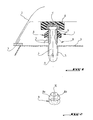
- reference 1 designates an adjustable stop that can be used between a movable element 2 of the body of a motor vehicle and a structural element 3 of the body of this vehicle to position element 2 relative to item 3.
- the movable body element 2 can be an opening or bonnet of the vehicle which, when closed position, must be aligned or flush with the surrounding bodywork element 3 the movable element 2.
- element 2 is mounted articulated or pivotable relative to the element bodywork 3.
- the stop 1 comprises a body 4 mounted at sliding or slightly in force in a sheath 5 integral with the structural element 3 and a head control 6 made of a solid rubber material the stop body 4 opposite the sleeve 5.
- the stop 1 is then fixed relative to the structural element 3 of the bodywork in its position adjusted to position the movable element 2 relative to the structural element 3 at each element 2 closed.
- the stop 1 comprises a ring 8 carried by the stop body 4 so as not to move along this body only in a direction opposite to the head of command 6 to press on the element of body structure 3 and lock the body of stop 4 relative to element 3 at the set position of the stop surface of the stopper 1.
- the stop body 4 is cylindrical and includes over part of its length circular serrated notches 9 oriented in direction opposite the control head 6, i.e. towards the structural element 3, so as to allow the ring 8, locking, snap along of the stop body 4 in the opposite direction to the head of command 6 and to oppose the sliding movement from the stop 1 in the sleeve 4 to the set position of stop.
- the ring 8 of generally cylindrical shape, has its end located on the side of the stop head 6 which is axially split at 10 so as to define two parts radially elastic opposites 8a, 8b ensuring latching with the notches 9 of the stop body 4 and the locking this body to the structural element of the body.
- each part 8a, 8b of the ring 8 is engaged elastically at the bottom of the shoulder perpendicular to the longitudinal axis of the stop body 4 defining a circular toothed notch 9 to prevent the movement of the stopper 1 in the direction indicated by the arrow A and thus keep the stopper in its position adjusted when the movable body element 2 comes to each time pressing the control head 6.
- the two parts end 8a, 8b of the ring 8 can be truncated.
- the end of the locking ring 8 can be split axially crosswise to define four radially elastic and two-by-two end portions diagonally opposite.
- the stop body 4 instead of being cylindrical, may be of square section and movable at sliding in a sleeve 5 of conjugate shape.
- the abutment body 4 comprises two series of notches sawtooth 9 made respectively on the two opposite sides of the body 4, each notch of a series being straight and extending transversely to the direction longitudinal of the stop body 4.
- the ring lock 8 will have a central shaped hole combined with the stop body 4 having at least two end portions with planar parallel internal surface the ends of which can engage elastically at the bottom of the respective serrated notches 9.
- stop 1 To prevent stop 1 from moving relative to the structural element 3 in the opposite direction to that of arrow A, it can be kept in the sheath 5 by friction or, if necessary, by any suitable positive locking means if stopper 1 should be used under conditions such as friction support would not be sufficient.
- the stop body 4 and the locking ring 8 can be made of plastic or in another suitable subject.
- control head 6 can be molded on a rigid plastic part 11 covering the end of the stop body 4 being fixed to this last for example by collage.
- the sheath 5 is made in one piece with the structural element 3 of the body of the vehicle so that there is no room intermediate link between sleeve and stop body 4.
- the sheath 5 is attached to the element of structure 3 by being integral with the latter by welding or by collage.
- the assembly constituted by the stop body 4, the control head 6 and the locking ring 8 is preassembled. Then, the stop thus formed is mounted in the sheath 5 of the structural element 3 of the vehicle body with locking ring 8 located near the control head 6.
- the stop body 4 is moved in the direction of arrow A to its position set to which element 2 moved stopper 1 to this position adjusted by contacting the control head 6.
- the ring 8 is maneuvered so as to snap it along of the stop body 4 until it comes to bear on the structural element 3 so that its end free engages elastically in the bottom of the notch corresponding sawtooth to lock stopper 1 in the direction indicated by arrow A and oppose everything subsequent movement of the stopper in this direction each time once the movable element 2 is brought to its position relative determined to the structural element 3.
- the adjustable stop according to the invention allows a quick adjustment of the position of its stop surface and is extremely simple in structure.
Landscapes
- Superstructure Of Vehicle (AREA)
- Braking Arrangements (AREA)
- Air-Conditioning For Vehicles (AREA)
- Lock And Its Accessories (AREA)
Claims (12)
- Einstellbarer Anschlag (1), welcher die Positionierung eines beweglichen Teils (2) einer Fahrzeugkarosserie relativ zu einem Strukturelement (3) der Karosserie ermöglicht, von der Art, die einen Betätigungskopf (6) aufweist, der fest mit einem Anschlagkorpus (4) verbunden ist, der gleitend in einem Element angebracht ist, das eine Hülse (5) bildet, die fest mit dem Strukturelement (3) so verbunden ist, dass die Gleitbewegung des Anschlags (1) in der Hülse in seiner von dem beweglichen Element (2) der Karosserie eingestellten Position möglich wird, welches auf den Betätigungskopf (6) einwirkt, und welcher des Weiteren einen Ring aufweist, dadurch gekennzeichnet, dass der Ring (8) von dem Korpus (4) des Anschlags in der Weise getragen wird, dass er sich entlang dieses Korpus nur in einer dem Betätigungskopf (6) entgegengesetzten Richtung so verschiebt, dass er auf dem Strukturelement (3) der Karosserie in Anlage kommt und den Korpus (4) des Anschlags relativ zu dem Strukturelement (2) der Karosserie in der vom Anschlag (1) eingestellten Position verriegelt.
- Einstellbarer Anschlag nach Anspruch 1, dadurch gekennzeichnet, dass der Korpus (4) des Anschlags auf einem Abschnitt seiner Länge mindestens zwei einander gegenüber liegende Reihen von sägezahnförmigen Einkerbungen (9) aufweist, die in eine Richtung ausgerichtet sind, die dem Betätigungskopf (6) in der Weise entgegengesetzt ist, dass der Verriegelungsring (8) durch Einrasten entlang des Korpus des Anschlags (4) in einer Richtung verschieblich ist, die dem Betätigungskopf entgegengesetzt ist, und der Gleitbewegung des Anschlags (1) entgegenwirkt, wenn dieser sich in seiner eingestellten Position befindet.
- Einstellbarer Anschlag nach Anspruch 2, dadurch gekennzeichnet, dass der Korpus (4) des Anschlags zylinderförmig ist und die Einkerbungen (9) kreisförmig sind.
- Einstellbarer Anschlag nach Anspruch 2 oder 3, dadurch gekennzeichnet, dass der Ring (8) eine ganz allgemein zylindrische Form aufweist und sein Ende, das neben dem Anschlagkopf (6) liegt, in axialer Richtung so geschlitzt ist, dass mindestens zwei radial einander gegenüberliegende elastische Abschnitte (8a, 8b) definiert werden, wobei die Verrastung des Korpus (4) des Anschlags mit den Einkerbungen (9) und die Verriegelung dieses Korpus an dem Strukturelement (3) der Karosserie sichergestellt sind und diese dabei elastisch in Anlage auf den jeweiligen Einkerbungen (9) gehalten werden.
- Einstellbarer Anschlag nach Anspruch 3, dadurch gekennzeichnet, dass das Ende des Ringes (8) in axialer Richtung kreuzförmig so geschlitzt ist, dass vier in radialer Richtung elastische Endabschnitte definiert werden, die jeweils zu zweien einander diagonal gegenüber liegen.
- Einstellbarer Anschlag nach Anspruch 4 oder 5, dadurch gekennzeichnet, dass das Ende des Ringes (8) kegelstumpfförmig ist.
- Einstellbarer Anschlag nach einem der vorhergehenden Ansprüche, dadurch gekennzeichnet, dass der Betätigungskopf (6) aus einem Werkstoff auf Gummibasis gebildet ist, der auf einem Stück aus starrem Kunststoffmaterial (11) zur Befestigung am Korpus (4) des Anschlags abgeformt wird.
- Einstellbarer Anschlag nach einem der vorhergehenden Ansprüche, dadurch gekennzeichnet, dass der Korpus (4) des Anschlags und der Verriegelungsring (8) aus einem Kunststoffmaterial hergestellt sind.
- Einstellbarer Anschlag nach einem der vorhergehenden Ansprüche, dadurch gekennzeichnet, dass der Korpus (4) des Anschlags in der Hülse (5) unter Reibung gleitend angebracht ist, um den Anschlag (1) in seiner Stellung zu halten, ehe er in seiner eingestellten Position verriegelt wird.
- Einstellbarer Anschlag nach einem der vorhergehenden Ansprüche, dadurch gekennzeichnet, dass die Hülse (5) aus einem einzigen Stück mit dem Strukturelement (3) der Fahrzeugkarosserie ausgebildet ist.
- Einstellbarer Anschlag nach Anspruch 10, dadurch gekennzeichnet, dass das bewegliche Element (2) der Karosserie ein Schiebedach oder eine Motorhaube des Fahrzeugs ist.
- Verfahren zum Einstellen der Positionierung der Haltefläche eines einstellbaren Anschlags (1), wie er in einem der vorhergehenden Ansprüche definiert und zwischen einem beweglichen Element (2) der Karosserie eines Kraftfahrzeugs und einem Strukturelement (3) der Karosserie angeordnet ist, dadurch gekennzeichnet, dass es darin besteht, den Anschlag (1) in der Hülse (5) mit dem Verriegelungsring zu montieren, der dabei in der Nähe des Betätigungskopfes liegt, sowie das bewegliche Element (2) der Karosserie in ihrer Einstellposition relativ zu dem Strukturelement (3) der Karosserie anzuordnen, um über den Betätigungskopf (6), der mit dem beweglichen Element (2) der Karosserie in Berührung steht, die Verschiebung durch Gleiten des Korpus (4) des Anschlags in der Hülse (5) auf seiner Einstellhöhe herbeizuführen, und den Ring (8) entlang des Korpus (4) des Anschlags so zu verschieben, dass er in Anlage auf dem Strukturelement (3) der Karosserie in seiner Eosition zur Verriegelung des Anschlags (1) in dessen Einstellposition gebracht wird.
Applications Claiming Priority (2)
| Application Number | Priority Date | Filing Date | Title |
|---|---|---|---|
| FR0112923 | 2001-10-08 | ||
| FR0112923A FR2830584B1 (fr) | 2001-10-08 | 2001-10-08 | Butee reglable pour elements mobiles de carrosserie de vehicule automobile |
Publications (2)
| Publication Number | Publication Date |
|---|---|
| EP1300535A1 EP1300535A1 (de) | 2003-04-09 |
| EP1300535B1 true EP1300535B1 (de) | 2004-07-07 |
Family
ID=8868035
Family Applications (1)
| Application Number | Title | Priority Date | Filing Date |
|---|---|---|---|
| EP02292471A Expired - Lifetime EP1300535B1 (de) | 2001-10-08 | 2002-10-07 | Einstellbarer Anschlag für bewegliche Teile einer Fahrzeugkarosserie |
Country Status (5)
| Country | Link |
|---|---|
| EP (1) | EP1300535B1 (de) |
| AT (1) | ATE270741T1 (de) |
| DE (1) | DE60200712T2 (de) |
| ES (1) | ES2224034T3 (de) |
| FR (1) | FR2830584B1 (de) |
Families Citing this family (1)
| Publication number | Priority date | Publication date | Assignee | Title |
|---|---|---|---|---|
| FR2884475B1 (fr) | 2005-04-14 | 2007-06-08 | Peugeot Citroen Automobiles Sa | Butee retractable au choc pour vehicule automobile |
Family Cites Families (3)
| Publication number | Priority date | Publication date | Assignee | Title |
|---|---|---|---|---|
| US3336962A (en) * | 1966-04-03 | 1967-08-22 | United Carr Inc | Threaded nut lock |
| FR2801626B1 (fr) * | 1999-11-26 | 2002-03-01 | Peugeot Citroen Automobiles Sa | Butee de fin de course d'une partie ouvrante de la carrosserie d'un vehicule automobile et procede de pose et de reglage de la butee |
| JP4329888B2 (ja) * | 2000-07-06 | 2009-09-09 | 株式会社ニフコ | 緩衝装置 |
-
2001
- 2001-10-08 FR FR0112923A patent/FR2830584B1/fr not_active Expired - Fee Related
-
2002
- 2002-10-07 ES ES02292471T patent/ES2224034T3/es not_active Expired - Lifetime
- 2002-10-07 DE DE60200712T patent/DE60200712T2/de not_active Expired - Lifetime
- 2002-10-07 EP EP02292471A patent/EP1300535B1/de not_active Expired - Lifetime
- 2002-10-07 AT AT02292471T patent/ATE270741T1/de not_active IP Right Cessation
Also Published As
| Publication number | Publication date |
|---|---|
| ATE270741T1 (de) | 2004-07-15 |
| DE60200712T2 (de) | 2005-07-28 |
| DE60200712D1 (de) | 2004-08-12 |
| FR2830584A1 (fr) | 2003-04-11 |
| ES2224034T3 (es) | 2005-03-01 |
| FR2830584B1 (fr) | 2004-02-06 |
| EP1300535A1 (de) | 2003-04-09 |
Similar Documents
| Publication | Publication Date | Title |
|---|---|---|
| EP2007260A2 (de) | Entfernbare greifvorrichtung | |
| FR2963586A1 (fr) | Glissiere pour siege de vehicule automobile a verrouillage lateral sans jeu | |
| EP0919679A1 (de) | Schnappverriegelungseinrichtung, insbesondere für die Befestigung eines Fahrzeugsitzes am Fahrzeugboden | |
| FR2770880A1 (fr) | Ensemble pour le positionnement, le centrage et le maintien en service d'une piece mecanique | |
| EP1911624A2 (de) | System zur lösbaren Montage eines ersten Elements auf einem zweiten Element, insbesondere für einen Rücksitz eines Kraftfahrzeugs | |
| EP3412524B1 (de) | Lager, das einen haltearm eines steuerstands in einer transportposition umfasst, entsprechende untereinheit des steuerstands und entsprechender steuerstand sowie blockierverfahren eines steuerstands in seiner transportposition | |
| EP1300535B1 (de) | Einstellbarer Anschlag für bewegliche Teile einer Fahrzeugkarosserie | |
| EP0797718B1 (de) | Provisorischer türanschlag für ein kraftfahrzeugscharnier und vorrichtung um diesen anzubringen | |
| FR2861114A1 (fr) | Cle d'actionnement d'une serrure | |
| EP3412522B1 (de) | Haltevorrichtung eines steuerstands eines reinigungsmechanismus, lager eines steuerstands, entsprechende untereinheit eines steuerstands und entsprechender steuerstand, und einsatzverfahren einer haltevorrichtung in einen steuerstand | |
| FR2697866A1 (fr) | Lève-vitre pour véhicule automobile. | |
| EP1258389B1 (de) | Verschlussvorrichtung für eine Öffnung zum Befestigen eines Gegenstandes, wie z.B. einen Kraftfahrzeugsitz | |
| FR2751710A1 (fr) | Attache rapide a baionnette pour le raccordement de deux organes de direction, notamment d'un vehicule automobile | |
| EP1426227B1 (de) | Einbauvorrichtung einer Rückholfeder für einen Schalthebel eines Kraftfahrzeuges | |
| FR2658878A1 (fr) | Dispositif de connexion rapide entre deux portions d'une timonerie, notamment pour vehicule automobile. | |
| FR2821898A1 (fr) | Ensemble pour vehicule automobile, comprenant un element de structure, une piece rapportee et un organe de montage, procede de realisation et vehicule automobile correspondants | |
| FR2695693A1 (fr) | Dispositif d'immobilisation d'une gaine de câble sur un support quelconque. | |
| EP3938667B1 (de) | Pyrotechnische vorrichtung zum lösen von muttern | |
| EP1270962B1 (de) | Gesicherte, mechanische Verbindungsvorrichtung | |
| FR2917794A1 (fr) | Dispositif de fixation inviolable d'une piece dans une decoupe prevue sur une structure. | |
| FR2768196A1 (fr) | Fixation auto-liberante au serrage, notamment pour une aile plastique d'un vehicule automobile | |
| FR2887652A1 (fr) | Dispositif de liaison autobloquante entre une pedale de frein d'un vehicule automobile et une tige de commande d'un amplificateur d'effort de freinage de ce vehicule | |
| FR2662654A1 (fr) | Pare-chocs a fixation reglable pour vehicule automobile. | |
| WO2024023255A1 (fr) | Dispositif d'obturation | |
| EP1088172B1 (de) | Haltevorrichtung für ein in eine trägeröffnung eingebrachtes element |
Legal Events
| Date | Code | Title | Description |
|---|---|---|---|
| PUAI | Public reference made under article 153(3) epc to a published international application that has entered the european phase |
Free format text: ORIGINAL CODE: 0009012 |
|
| AK | Designated contracting states |
Kind code of ref document: A1 Designated state(s): AT BE BG CH CY CZ DE DK EE ES FI FR GB GR IE IT LI LU MC NL PT SE SK TR |
|
| AX | Request for extension of the european patent |
Extension state: AL LT LV MK RO SI |
|
| 17P | Request for examination filed |
Effective date: 20030917 |
|
| GRAP | Despatch of communication of intention to grant a patent |
Free format text: ORIGINAL CODE: EPIDOSNIGR1 |
|
| AKX | Designation fees paid |
Designated state(s): AT BE BG CH CY CZ DE DK EE ES FI FR GB GR IE IT LI LU MC NL PT SE SK TR |
|
| GRAS | Grant fee paid |
Free format text: ORIGINAL CODE: EPIDOSNIGR3 |
|
| GRAA | (expected) grant |
Free format text: ORIGINAL CODE: 0009210 |
|
| AK | Designated contracting states |
Kind code of ref document: B1 Designated state(s): AT BE BG CH CY CZ DE DK EE ES FI FR GB GR IE IT LI LU MC NL PT SE SK TR |
|
| PG25 | Lapsed in a contracting state [announced via postgrant information from national office to epo] |
Ref country code: TR Free format text: LAPSE BECAUSE OF FAILURE TO SUBMIT A TRANSLATION OF THE DESCRIPTION OR TO PAY THE FEE WITHIN THE PRESCRIBED TIME-LIMIT Effective date: 20040707 Ref country code: NL Free format text: LAPSE BECAUSE OF FAILURE TO SUBMIT A TRANSLATION OF THE DESCRIPTION OR TO PAY THE FEE WITHIN THE PRESCRIBED TIME-LIMIT Effective date: 20040707 Ref country code: AT Free format text: LAPSE BECAUSE OF FAILURE TO SUBMIT A TRANSLATION OF THE DESCRIPTION OR TO PAY THE FEE WITHIN THE PRESCRIBED TIME-LIMIT Effective date: 20040707 Ref country code: SK Free format text: LAPSE BECAUSE OF FAILURE TO SUBMIT A TRANSLATION OF THE DESCRIPTION OR TO PAY THE FEE WITHIN THE PRESCRIBED TIME-LIMIT Effective date: 20040707 Ref country code: FI Free format text: LAPSE BECAUSE OF FAILURE TO SUBMIT A TRANSLATION OF THE DESCRIPTION OR TO PAY THE FEE WITHIN THE PRESCRIBED TIME-LIMIT Effective date: 20040707 Ref country code: IE Free format text: LAPSE BECAUSE OF FAILURE TO SUBMIT A TRANSLATION OF THE DESCRIPTION OR TO PAY THE FEE WITHIN THE PRESCRIBED TIME-LIMIT Effective date: 20040707 Ref country code: CZ Free format text: LAPSE BECAUSE OF FAILURE TO SUBMIT A TRANSLATION OF THE DESCRIPTION OR TO PAY THE FEE WITHIN THE PRESCRIBED TIME-LIMIT Effective date: 20040707 Ref country code: CY Free format text: LAPSE BECAUSE OF FAILURE TO SUBMIT A TRANSLATION OF THE DESCRIPTION OR TO PAY THE FEE WITHIN THE PRESCRIBED TIME-LIMIT Effective date: 20040707 Ref country code: EE Free format text: LAPSE BECAUSE OF FAILURE TO SUBMIT A TRANSLATION OF THE DESCRIPTION OR TO PAY THE FEE WITHIN THE PRESCRIBED TIME-LIMIT Effective date: 20040707 Ref country code: BG Free format text: LAPSE BECAUSE OF FAILURE TO SUBMIT A TRANSLATION OF THE DESCRIPTION OR TO PAY THE FEE WITHIN THE PRESCRIBED TIME-LIMIT Effective date: 20040707 |
|
| REG | Reference to a national code |
Ref country code: GB Ref legal event code: FG4D Free format text: NOT ENGLISH |
|
| REG | Reference to a national code |
Ref country code: CH Ref legal event code: EP |
|
| REG | Reference to a national code |
Ref country code: IE Ref legal event code: FG4D Free format text: FRENCH |
|
| REF | Corresponds to: |
Ref document number: 60200712 Country of ref document: DE Date of ref document: 20040812 Kind code of ref document: P |
|
| PG25 | Lapsed in a contracting state [announced via postgrant information from national office to epo] |
Ref country code: SE Free format text: LAPSE BECAUSE OF FAILURE TO SUBMIT A TRANSLATION OF THE DESCRIPTION OR TO PAY THE FEE WITHIN THE PRESCRIBED TIME-LIMIT Effective date: 20041007 Ref country code: LU Free format text: LAPSE BECAUSE OF NON-PAYMENT OF DUE FEES Effective date: 20041007 Ref country code: DK Free format text: LAPSE BECAUSE OF FAILURE TO SUBMIT A TRANSLATION OF THE DESCRIPTION OR TO PAY THE FEE WITHIN THE PRESCRIBED TIME-LIMIT Effective date: 20041007 Ref country code: GR Free format text: LAPSE BECAUSE OF FAILURE TO SUBMIT A TRANSLATION OF THE DESCRIPTION OR TO PAY THE FEE WITHIN THE PRESCRIBED TIME-LIMIT Effective date: 20041007 |
|
| PG25 | Lapsed in a contracting state [announced via postgrant information from national office to epo] |
Ref country code: BE Free format text: LAPSE BECAUSE OF NON-PAYMENT OF DUE FEES Effective date: 20041031 Ref country code: MC Free format text: LAPSE BECAUSE OF NON-PAYMENT OF DUE FEES Effective date: 20041031 |
|
| GBT | Gb: translation of ep patent filed (gb section 77(6)(a)/1977) |
Effective date: 20041008 |
|
| NLV1 | Nl: lapsed or annulled due to failure to fulfill the requirements of art. 29p and 29m of the patents act | ||
| REG | Reference to a national code |
Ref country code: ES Ref legal event code: FG2A Ref document number: 2224034 Country of ref document: ES Kind code of ref document: T3 |
|
| REG | Reference to a national code |
Ref country code: IE Ref legal event code: FD4D |
|
| BERE | Be: lapsed |
Owner name: PEUGEOT CITROEN AUTOMOBILES SA Effective date: 20041031 |
|
| PLBE | No opposition filed within time limit |
Free format text: ORIGINAL CODE: 0009261 |
|
| STAA | Information on the status of an ep patent application or granted ep patent |
Free format text: STATUS: NO OPPOSITION FILED WITHIN TIME LIMIT |
|
| 26N | No opposition filed |
Effective date: 20050408 |
|
| PG25 | Lapsed in a contracting state [announced via postgrant information from national office to epo] |
Ref country code: LI Free format text: LAPSE BECAUSE OF NON-PAYMENT OF DUE FEES Effective date: 20061031 Ref country code: CH Free format text: LAPSE BECAUSE OF NON-PAYMENT OF DUE FEES Effective date: 20061031 |
|
| REG | Reference to a national code |
Ref country code: GB Ref legal event code: 746 Effective date: 20070117 |
|
| REG | Reference to a national code |
Ref country code: CH Ref legal event code: PL |
|
| BERE | Be: lapsed |
Owner name: S.A. *PEUGEOT CITROEN AUTOMOBILES Effective date: 20041031 |
|
| PG25 | Lapsed in a contracting state [announced via postgrant information from national office to epo] |
Ref country code: PT Free format text: LAPSE BECAUSE OF NON-PAYMENT OF DUE FEES Effective date: 20041207 |
|
| REG | Reference to a national code |
Ref country code: ES Ref legal event code: GC2A Effective date: 20110406 |
|
| PGFP | Annual fee paid to national office [announced via postgrant information from national office to epo] |
Ref country code: FR Payment date: 20111118 Year of fee payment: 10 |
|
| PGFP | Annual fee paid to national office [announced via postgrant information from national office to epo] |
Ref country code: GB Payment date: 20120924 Year of fee payment: 11 |
|
| PGFP | Annual fee paid to national office [announced via postgrant information from national office to epo] |
Ref country code: IT Payment date: 20120924 Year of fee payment: 11 |
|
| PGFP | Annual fee paid to national office [announced via postgrant information from national office to epo] |
Ref country code: DE Payment date: 20120924 Year of fee payment: 11 |
|
| PGFP | Annual fee paid to national office [announced via postgrant information from national office to epo] |
Ref country code: ES Payment date: 20120920 Year of fee payment: 11 |
|
| REG | Reference to a national code |
Ref country code: FR Ref legal event code: ST Effective date: 20130628 |
|
| PG25 | Lapsed in a contracting state [announced via postgrant information from national office to epo] |
Ref country code: FR Free format text: LAPSE BECAUSE OF NON-PAYMENT OF DUE FEES Effective date: 20121031 |
|
| GBPC | Gb: european patent ceased through non-payment of renewal fee |
Effective date: 20131007 |
|
| PG25 | Lapsed in a contracting state [announced via postgrant information from national office to epo] |
Ref country code: GB Free format text: LAPSE BECAUSE OF NON-PAYMENT OF DUE FEES Effective date: 20131007 |
|
| REG | Reference to a national code |
Ref country code: DE Ref legal event code: R119 Ref document number: 60200712 Country of ref document: DE Effective date: 20140501 |
|
| PG25 | Lapsed in a contracting state [announced via postgrant information from national office to epo] |
Ref country code: IT Free format text: LAPSE BECAUSE OF NON-PAYMENT OF DUE FEES Effective date: 20131007 Ref country code: DE Free format text: LAPSE BECAUSE OF NON-PAYMENT OF DUE FEES Effective date: 20140501 |
|
| REG | Reference to a national code |
Ref country code: ES Ref legal event code: FD2A Effective date: 20141107 |
|
| PG25 | Lapsed in a contracting state [announced via postgrant information from national office to epo] |
Ref country code: ES Free format text: LAPSE BECAUSE OF NON-PAYMENT OF DUE FEES Effective date: 20131008 |