EP0799759B1 - Einrichtung zum Halten eines Plastik-Kotflügels an einem metallenen Fahrzeugteil - Google Patents
Einrichtung zum Halten eines Plastik-Kotflügels an einem metallenen Fahrzeugteil Download PDFInfo
- Publication number
- EP0799759B1 EP0799759B1 EP19970400714 EP97400714A EP0799759B1 EP 0799759 B1 EP0799759 B1 EP 0799759B1 EP 19970400714 EP19970400714 EP 19970400714 EP 97400714 A EP97400714 A EP 97400714A EP 0799759 B1 EP0799759 B1 EP 0799759B1
- Authority
- EP
- European Patent Office
- Prior art keywords
- wing
- shoe
- metal support
- plastic
- profiled member
- Prior art date
- Legal status (The legal status is an assumption and is not a legal conclusion. Google has not performed a legal analysis and makes no representation as to the accuracy of the status listed.)
- Expired - Lifetime
Links
- 239000002184 metal Substances 0.000 claims description 29
- 238000006073 displacement reaction Methods 0.000 claims description 4
- 238000001816 cooling Methods 0.000 description 8
- 210000002105 tongue Anatomy 0.000 description 4
- 230000010339 dilation Effects 0.000 description 3
- 238000000465 moulding Methods 0.000 description 3
- 229910000831 Steel Inorganic materials 0.000 description 2
- 238000010438 heat treatment Methods 0.000 description 2
- 210000002445 nipple Anatomy 0.000 description 2
- 238000010422 painting Methods 0.000 description 2
- 239000010959 steel Substances 0.000 description 2
- 238000004381 surface treatment Methods 0.000 description 2
- 230000000903 blocking effect Effects 0.000 description 1
- 238000010411 cooking Methods 0.000 description 1
- 230000000694 effects Effects 0.000 description 1
- 239000000463 material Substances 0.000 description 1
- 239000003973 paint Substances 0.000 description 1
- 125000006850 spacer group Chemical group 0.000 description 1
Images

Classifications
-
- B—PERFORMING OPERATIONS; TRANSPORTING
- B62—LAND VEHICLES FOR TRAVELLING OTHERWISE THAN ON RAILS
- B62D—MOTOR VEHICLES; TRAILERS
- B62D29/00—Superstructures, understructures, or sub-units thereof, characterised by the material thereof
- B62D29/04—Superstructures, understructures, or sub-units thereof, characterised by the material thereof predominantly of synthetic material
- B62D29/048—Connections therefor, e.g. joints
-
- B—PERFORMING OPERATIONS; TRANSPORTING
- B60—VEHICLES IN GENERAL
- B60G—VEHICLE SUSPENSION ARRANGEMENTS
- B60G2204/00—Indexing codes related to suspensions per se or to auxiliary parts
- B60G2204/40—Auxiliary suspension parts; Adjustment of suspensions
- B60G2204/44—Centering or positioning means
- B60G2204/4404—Retainers for holding a fixing element, e.g. bushing, nut, bolt etc., until it is tightly fixed in position
Definitions
- the invention relates to a device for retaining a plastic element of bodywork, in particular a plastic wing of a motor vehicle on a metal support.
- the invention relates more particularly to a retaining device according to the preamble of claim 1 of a plastic bodywork element on a metal support, the coefficient of expansion is less than that of said plastic element, as described in the closest prior art shown in US-A-4,707,020.
- the publication FR-A-2720794 describes a device for retaining an element body plastic on a metal support in which a staple for fixing said plastic element to the support, the coefficient of expansion is less than that of the plastic element, consists in particular by a fixing base, the fixing base carrying perpendicularly support tabs on the plastic element, said tabs being integral with a spacer provided with a through hole a fixing screw.
- a device allows, after the attachment of the wing on the body, during assembly, the free expansion of said wing during a surface treatment requiring an increase in temperature.
- the inner lateral edges of the wing follow the edges side of the clip thus ensuring, not only a blocking of the wing in lateral direction but also in the longitudinal direction of the vehicle.
- the wing undergoes a dilation according to all its dimensions therefore in particular according to its lateral dimension. So, from the beginning of expansion, the inner side edges of the wing move away from lateral edges of the clip then allowing the longitudinal expansion of the wing, longitudinal expansion which is much more important than the expansion lateral due to the very shape of the wing.
- the wing takes up the position to which it was fixed during assembly.
- temperature variations cause further shrinkage of the plastic below the initial dimensions of the wing, withdrawal which does not occur only after cooling, while the wing is blocked again longitudinally on the clip. This withdrawal causes, in the case of a wing front, a spacing of the rear end of said wing relative to the front end of the front door, causing an increase unsightly of the play of aspect existing between the wing and the door.
- the invention aims to overcome this drawback.
- the invention relates to a device for retaining a plastic element of bodywork on a metal support whose coefficient of expansion is lower than that of said plastic element, the device being of the type comprising a profiled element mounted inside the plastic element.
- the device is characterized in that the profiled element is secured to the metal support by means of connecting means allowing a displacement of said profiled element relative to said metal support.
- the connecting means are formed by a shoe fixed on the metal support, the profiled element being mounted in translation on said shoe and returned to abutment by means elastic.
- This characteristic gives the plastic element freedom in translation relative to the metal support, and this after cooling of said plastic element, which allows taking into counts the additional plastic removal after cooling.
- the shoe protrudes from the face bottom of the element profiled by a tab intended to enter into a first groove made on the part of the plastic element ensuring fixing on the metal support.
- the profiled element comprises a post intended to be clipped to the bottom of a second groove converging formed on the corresponding wall of the plastic element.
- the elastic means are constituted by an elastic blade made in one piece with the element profiled, said elastic blade cooperating with a protuberance located at the skate surface.
- the elastic blade can thus be obtained by molding in one piece with the profiled part, which is particularly simple and economical.
- the profiled element is mounted translation on the skate via a dovetail.
- the shoe is fixed on the metal support by means of a screw passing through a hole in said support metallic to be screwed into a threaded hole made in said shoe.
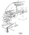
- Figure 1 shows schematically the mounting of a plastic wing 1 on a support metal 2 using a fixing device 3 and a screw 4.
- the fastening device 3 consists of a profiled element 5 whose shape outer conforms to the inner shape of the wing 1 and of a shoe 6 mounted in translation on the underside of the profiled element 5, in the direction of the X axis corresponding to the length of the vehicle.
- Pad 6 protrudes by the underside of the profiled element 5 by a tongue 6a intended to fit into a first groove made on the horizontal part of the wing in contact with the metal support 2.
- the profiled element 5 laterally has a stud 5a intended to be clipped to the bottom of a second converging groove 1b made on the side wall corresponding to wing 1.
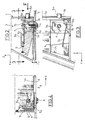
- FIGS. 2 and 3 A particular variant embodiment of the fixing device 3 is detailed in FIGS. 2 and 3: the profiled element 5 is mounted in translation on the shoe 6 by means of a dovetail 6c. Pad 6 is drilled by a vertical hole 6b emerging. Profile element 5 is recalled in translation on the shoe 6 against a stop 5b belonging to said element section 5, in the direction of the negative X, by elastic means. According to the particular variant shown in the figures, these means consist of an elastic blade 5c. We have shown an elastic blade 5c reported to facilitate understanding but it is clear that said blade 5c could be made in one piece with the profiled element 5, for example by molding.
- a staple 7 in the form of "U" consisting of a core 7a connecting a small wing 7b and a large wing 7c, the core 7a being pierced with a hole 7d, is mounted in the shoe 6.
- the two wings 7b, 7c are driven into vertical grooves of said shoe 6 so as to bring the core 7a against the tongue 6a and to make coincide holes 6b and 7d.
- the large wing 7c protrudes above the body of the skate 6 so as to hook the blade 5c and thus maintain the profiled element 5 on pad 6.
- any other elastic means would be suitable also, for example a spring connecting the shoe 6 to the element profile 5.
- the fixing device 3 thus formed is mounted on the wing 1 fitted in the first groove 1a of the wing 1 by the tongue 6a of the shoe 6 until the pin 5a clips into the bottom of the second groove 1b of the wing 1, thus joining the fastening device 3 and wing 1.
- the assembly thus formed can be manipulated and brought to the metal support 2 without special precautions.
- the actual screwing takes place between the threads of the screw 4 and the sheet metal constituting the edges of the hole 7d of the clip 7, the hole 6b being used only for the passage of the screw 4.
- FIG. 5 The assembly performed after adjusting the clearances is shown in Figures 4 and 5. It can be seen in FIG. 5 that the side walls of the element profile 5 are in close contact with the inner side walls of wing 1. During a significant rise in temperature, corresponding for example when painting the paint, there is a dilation of wing 1, dilation which tends to spread the inner side walls of the wing 1 of the side walls of the profiled element 5 thus allowing free longitudinal expansion in the direction of positive X's; indeed, wing 1 is blocked in translation in the direction of negative X because fixed positively at the vehicle door (not shown on the figures). The wing 1 in the expanded position is shown in FIG. 6.
- the second converging groove 1b will return gradually towards the position it occupied after mounting, which is shown in Figure 5. But, as soon as the groove 1b comes into contact with the nipple 5a, it drives the latter in its movement of translation in the direction of the negative X, because the pin 5a is integral with the profiled element 5 itself movable in translation in the X direction negative with respect to the shoe 6 fixed on the metal support 2. Indeed, the translation of the profiled element 5 in the direction of the negative X axis is not prevented by a positive stop as is the case in the other direction with the stop 5b, but simply braked by the restoring force of the leaf spring 5c secured to the profiled element 5 and bearing against the large wing 7c of the clip 7 which is embedded in the shoe 6.
- the plastic of wing 1 undergoes, after return to room temperature, an additional shrinkage which causes a reduction in the dimensions of wing 1 compared to the dimensions before heating.
- the additional withdrawal will result in additional displacement of wing 1 and as a result of the second groove 1b in the direction of the negative X, thus completing the clipping of said stud 5a into said groove 1b to reach the position represented in FIG. 8.
- the additional mobility provided to wing 1, relative to the metal support 2, by the stroke of the shoe 6 therefore allows to compensate for the additional shrinkage of the plastic, after cooling.
- the role of the elastic means, and in particular of the blade 5c, is to ensure that the shoe 6 is well in abutment 5b at the bottom of the groove at the time of mounting the fixing device 3 on the metal support 2 during fitting the wing 1.
Landscapes
- Engineering & Computer Science (AREA)
- Architecture (AREA)
- Structural Engineering (AREA)
- Chemical & Material Sciences (AREA)
- Combustion & Propulsion (AREA)
- Transportation (AREA)
- Mechanical Engineering (AREA)
- Connection Of Plates (AREA)
- Catalysts (AREA)
- Body Structure For Vehicles (AREA)
- Vehicle Interior And Exterior Ornaments, Soundproofing, And Insulation (AREA)
Claims (6)
- Vorrichtung zur Befestigung eines Kunststoffteils (1) einer Karosserie auf einem Metallträger (2), dessen Ausdehnungskoeffizient kleiner als derjenige des Kunststoffteils (1) ist, wobei die Vorrichtung ein Profilteil (5) umfaßt, das im Innern des Kunststoffteils (1) montiert und mit dem Metallträger (2) durch Verbindungsmittel (6) verbunden ist, die eine Verschiebung dieses Profilteils (5) in Bezug auf den Metallträger (2) gestatten, wobei die Verbindungsmittel aus einem auf dem Metallträger (2) befestigten Gleitstück (6) bestehen und wobei das Profilteil (5) verschiebbar auf diesem Gleitstück (6) montiert ist, dadurch gekennzeichnet, daß das Profilteil (5) durch elastische Mittel (5c) gegen einen Anschlag (5b), der zum Profilteil (5) gehört, rückgestellt wird, wobei dieser Anschlag (5b) das Profilteil (5) hinsichtlich einer Verschiebung in der Ausdehnungsrichtung des Kunststoffteils (1) blockiert.
- Befestigungsvorrichtung nach dem vorhergehenden Anspruch, dadurch gekennzeichnet, daß das Gleitstück (6) aus der Unterseite des Profilteils (5) mittels einer Zunge (6a) herausragt, die dazu bestimmt ist, in einen ersten Schlitz (1a) eingeschoben zu werden, der an dem Teil des Kunststoffteils (1) vorgesehen ist, welcher die Befestigung auf dem Metallträger (2) gewährleistet.
- Befestigungsvorrichtung nach einem der Ansprüche 1 oder 2, dadurch gekennzeichnet, daß das Profilteil (5) einen Zapfen (5a) aufweist, der dazu bestimmt ist, im Innern eines zweiten, konvergierenden Schlitzes (1b), der an der entsprechenden Wand des Kunststoffteils (1) vorgesehen ist, verrastet zu werden.
- Befestigungsvorrichtung nach einem der Ansprüche 1 bis 3, dadurch gekennzeichnet, daß die elastischen Mittel aus einem Federblatt (5c) bestehen, das einstückig mit dem Profilteil (5) gefertigt ist, wobei dieses Federblatt (5c) mit einem Vorsprung zusammenwirkt, der sich auf der Oberfläche des Gleitstücks (6) befindet.
- Befestigungsvorrichtung nach einem der Ansprüche 1 bis 4, dadurch gekennzeichnet, daß das Profilteil (5) mittels eines Schwalbenschwanzes (6c) verschiebbar auf dem Gleitstück (6) montiert ist.
- Befestigungsvorrichtung nach einem der Ansprüche 1 bis 5, dadurch gekennzeichnet, daß das Gleitstück (6) auf dem Metallträger (2) mittels einer Schraube (4) befestigt wird, die ein Loch (2a) dieses Metallträgers (2) durchsetzt, um in eine in dem Gleitstück (6) vorgesehene Gewindebohrung (6b) eingeschraubt zu werden.
Applications Claiming Priority (2)
| Application Number | Priority Date | Filing Date | Title |
|---|---|---|---|
| FR9604318A FR2747092B1 (fr) | 1996-04-05 | 1996-04-05 | Perfectionnement a un dispositif de retenue d'une aile plastique sur une caisse metallique |
| FR9604318 | 1996-04-05 |
Publications (2)
| Publication Number | Publication Date |
|---|---|
| EP0799759A1 EP0799759A1 (de) | 1997-10-08 |
| EP0799759B1 true EP0799759B1 (de) | 2001-05-16 |
Family
ID=9490969
Family Applications (1)
| Application Number | Title | Priority Date | Filing Date |
|---|---|---|---|
| EP19970400714 Expired - Lifetime EP0799759B1 (de) | 1996-04-05 | 1997-03-28 | Einrichtung zum Halten eines Plastik-Kotflügels an einem metallenen Fahrzeugteil |
Country Status (4)
| Country | Link |
|---|---|
| EP (1) | EP0799759B1 (de) |
| DE (1) | DE69704806T2 (de) |
| ES (1) | ES2157052T3 (de) |
| FR (1) | FR2747092B1 (de) |
Cited By (1)
| Publication number | Priority date | Publication date | Assignee | Title |
|---|---|---|---|---|
| EP1319581A2 (de) | 2001-12-11 | 2003-06-18 | Volkswagen Aktiengesellschaft | Kotflügel aus Kunststoff an Kraftfahrzeugen |
Families Citing this family (7)
| Publication number | Priority date | Publication date | Assignee | Title |
|---|---|---|---|---|
| DE10060782A1 (de) * | 2000-12-07 | 2002-06-13 | Bayerische Motoren Werke Ag | Vorrichtung zum Befestigen von zwei Bauteilen |
| US7261489B2 (en) * | 2004-05-20 | 2007-08-28 | United Technologies Corporation | Fastener assembly for attaching a non-metal component to a metal component |
| DE102004052637A1 (de) * | 2004-10-29 | 2006-05-04 | Rehau Ag + Co | Anordnung zum Befestigen eines Bauteils |
| DE102006029294A1 (de) * | 2006-06-23 | 2007-12-27 | Rehau Ag + Co. | Befestigungsanordnung |
| DE202008010321U1 (de) * | 2008-08-02 | 2009-12-17 | Rehau Ag + Co | Kunststoffkotflügel und Kraftfahrzeug |
| EP2722258A1 (de) | 2012-10-17 | 2014-04-23 | Compagnie Plastic Omnium | Bauteil eines Kraftfahrzeugs, das gegen thermische Verformung resistent ist |
| DE202016001857U1 (de) * | 2016-03-21 | 2017-06-22 | Liebherr-Mischtechnik Gmbh | Fahrmischer |
Family Cites Families (5)
| Publication number | Priority date | Publication date | Assignee | Title |
|---|---|---|---|---|
| US4707020A (en) * | 1985-07-16 | 1987-11-17 | Honda Giken Kogyo Kabushiki Kaisha | Body structure of a motor vehicle having exterior panels made of synthetic resins |
| FR2632691B1 (fr) * | 1988-06-10 | 1990-08-31 | Renault | Agrafe de fixation de piece plastique |
| US5098765A (en) * | 1989-12-22 | 1992-03-24 | Chrysler Corportion | Fastening arrangement for plastic vehicle panel |
| US5429412A (en) * | 1993-08-26 | 1995-07-04 | Chrysler Corporation | Plastic fender retainer arrangement |
| FR2720794B1 (fr) * | 1994-06-01 | 1996-07-12 | Renault | Dispositif de retenue d'un élément plastique de carrosserie sur un support métallique et procédé de montage du dispositif. |
-
1996
- 1996-04-05 FR FR9604318A patent/FR2747092B1/fr not_active Expired - Lifetime
-
1997
- 1997-03-28 EP EP19970400714 patent/EP0799759B1/de not_active Expired - Lifetime
- 1997-03-28 DE DE1997604806 patent/DE69704806T2/de not_active Expired - Fee Related
- 1997-03-28 ES ES97400714T patent/ES2157052T3/es not_active Expired - Lifetime
Cited By (1)
| Publication number | Priority date | Publication date | Assignee | Title |
|---|---|---|---|---|
| EP1319581A2 (de) | 2001-12-11 | 2003-06-18 | Volkswagen Aktiengesellschaft | Kotflügel aus Kunststoff an Kraftfahrzeugen |
Also Published As
| Publication number | Publication date |
|---|---|
| ES2157052T3 (es) | 2001-08-01 |
| FR2747092A1 (fr) | 1997-10-10 |
| DE69704806T2 (de) | 2001-11-22 |
| FR2747092B1 (fr) | 1998-05-07 |
| DE69704806D1 (de) | 2001-06-21 |
| EP0799759A1 (de) | 1997-10-08 |
Similar Documents
| Publication | Publication Date | Title |
|---|---|---|
| EP0799758B1 (de) | Einrichtung zur gleitenden Befestigung eines Plastik-Kotflügels | |
| EP0799759B1 (de) | Einrichtung zum Halten eines Plastik-Kotflügels an einem metallenen Fahrzeugteil | |
| FR2759744A1 (fr) | Piece en matiere plastique a fixation glissante integree | |
| FR2779467A1 (fr) | Dispositif pour la pose d'un revetement a distance d'une paroi | |
| EP1326024B9 (de) | Befestigung zum Anbringen eines Teiles an eine Basis und um es in Bezug auf seine Umgebung zu setzen, insbesondere eines Karosserieteiles eines Kraftfahrzeuges | |
| FR2976987A1 (fr) | Dispositif de montage pour la fixation rotative et imperdable d'un element mecanique | |
| EP2062804A1 (de) | Vorrichtung und Verfahren zur Befestigung einer Kotflügeleinheit an der Wagenkastenwand eines Kraftfahrzeugs | |
| FR2768197A1 (fr) | Fixation auto-liberante au serrage, notamment pour une aile plastique d'un vehicule automobile | |
| EP2203618B1 (de) | Als abstandshalter zwischen einem öffnungselement und einem festgelegten element wirkende vorrichtung, insbesondere für ein kraftfahrzeug | |
| EP4480729B1 (de) | Vorrichtung zum spannen eines gegenstandes mit einem gurt | |
| EP3849876B1 (de) | Anordnung zur bildung eines verkleidungsgehäuses für eine lenksäule und fahrzeug mit einem solchen gehäuse | |
| EP1957733B1 (de) | Provisorische Verriegelungsvorrichtung | |
| FR2911106A1 (fr) | Support destine a la fixation d'un element de carrosserie en matiere plastique sur la structure d'un vehicule, element de carrosserie correspondant et utilisation du support. | |
| EP0845569A1 (de) | Laufradvorrichtung für Schiebetür | |
| FR2585756A1 (fr) | Dispositif de jonction entre boitier et prolongateur de cremone a tetiere et a tringles | |
| FR3025467A1 (fr) | Dispositif de fixation d'un element rapporte d'un vehicule, element rapporte d'un vehicule comprenant une partie dudit dispositif de fixation | |
| FR2861439A1 (fr) | Dispositif de fixation avec jeux d'une premiere piece a une seconde piece | |
| FR2720794A1 (fr) | Dispositif de retenue d'un élément plastique de carrosserie sur un support métallique et procédé de montage du dispositif. | |
| FR2711196A1 (fr) | Ecrou encagé à montage sur un rail ou analogue et assemblage obtenu à l'aide de cet écrou. | |
| FR2994932A1 (fr) | Dispositif d'assemblage par glissement de deux pieces de vehicule | |
| FR2705746A1 (fr) | Dispositif de fixation d'un élément, tel qu'accoudoir ou crosse de porte de véhicule automobile, à une structure fixe. | |
| FR2768199A1 (fr) | Systeme de fixation glissante d'une piece en matiere plastique a un support | |
| EP4534781A1 (de) | Verriegelungsbeschlag-steuervorrichtung für tür- oder fensterrahmen | |
| FR2921031A1 (fr) | Element de pare-chocs comprenant une peau de pare-chocs et un presseur, et vehicule automobile comprenant un tel element de pare-chocs | |
| EP4438911A1 (de) | Befestigungssystem an einem gewindebolzen |
Legal Events
| Date | Code | Title | Description |
|---|---|---|---|
| PUAI | Public reference made under article 153(3) epc to a published international application that has entered the european phase |
Free format text: ORIGINAL CODE: 0009012 |
|
| AK | Designated contracting states |
Kind code of ref document: A1 Designated state(s): BE DE ES GB IT |
|
| 17P | Request for examination filed |
Effective date: 19980310 |
|
| 17Q | First examination report despatched |
Effective date: 19990625 |
|
| GRAG | Despatch of communication of intention to grant |
Free format text: ORIGINAL CODE: EPIDOS AGRA |
|
| GRAG | Despatch of communication of intention to grant |
Free format text: ORIGINAL CODE: EPIDOS AGRA |
|
| GRAG | Despatch of communication of intention to grant |
Free format text: ORIGINAL CODE: EPIDOS AGRA |
|
| GRAH | Despatch of communication of intention to grant a patent |
Free format text: ORIGINAL CODE: EPIDOS IGRA |
|
| GRAH | Despatch of communication of intention to grant a patent |
Free format text: ORIGINAL CODE: EPIDOS IGRA |
|
| GRAA | (expected) grant |
Free format text: ORIGINAL CODE: 0009210 |
|
| AK | Designated contracting states |
Kind code of ref document: B1 Designated state(s): BE DE ES GB IT |
|
| GBT | Gb: translation of ep patent filed (gb section 77(6)(a)/1977) |
Effective date: 20010521 |
|
| REF | Corresponds to: |
Ref document number: 69704806 Country of ref document: DE Date of ref document: 20010621 |
|
| REG | Reference to a national code |
Ref country code: ES Ref legal event code: FG2A Ref document number: 2157052 Country of ref document: ES Kind code of ref document: T3 |
|
| ITF | It: translation for a ep patent filed | ||
| REG | Reference to a national code |
Ref country code: GB Ref legal event code: IF02 |
|
| PLBE | No opposition filed within time limit |
Free format text: ORIGINAL CODE: 0009261 |
|
| STAA | Information on the status of an ep patent application or granted ep patent |
Free format text: STATUS: NO OPPOSITION FILED WITHIN TIME LIMIT |
|
| 26N | No opposition filed | ||
| PGFP | Annual fee paid to national office [announced via postgrant information from national office to epo] |
Ref country code: IT Payment date: 20060331 Year of fee payment: 10 |
|
| PGFP | Annual fee paid to national office [announced via postgrant information from national office to epo] |
Ref country code: DE Payment date: 20070316 Year of fee payment: 11 |
|
| PGFP | Annual fee paid to national office [announced via postgrant information from national office to epo] |
Ref country code: ES Payment date: 20070329 Year of fee payment: 11 |
|
| GBPC | Gb: european patent ceased through non-payment of renewal fee |
Effective date: 20070328 |
|
| PGFP | Annual fee paid to national office [announced via postgrant information from national office to epo] |
Ref country code: BE Payment date: 20070419 Year of fee payment: 11 |
|
| PG25 | Lapsed in a contracting state [announced via postgrant information from national office to epo] |
Ref country code: GB Free format text: LAPSE BECAUSE OF NON-PAYMENT OF DUE FEES Effective date: 20070328 |
|
| BERE | Be: lapsed |
Owner name: *RENAULT Effective date: 20080331 |
|
| PGFP | Annual fee paid to national office [announced via postgrant information from national office to epo] |
Ref country code: GB Payment date: 20060322 Year of fee payment: 10 |
|
| PG25 | Lapsed in a contracting state [announced via postgrant information from national office to epo] |
Ref country code: DE Free format text: LAPSE BECAUSE OF NON-PAYMENT OF DUE FEES Effective date: 20081001 |
|
| PG25 | Lapsed in a contracting state [announced via postgrant information from national office to epo] |
Ref country code: BE Free format text: LAPSE BECAUSE OF NON-PAYMENT OF DUE FEES Effective date: 20080331 |
|
| REG | Reference to a national code |
Ref country code: ES Ref legal event code: FD2A Effective date: 20080329 |
|
| PG25 | Lapsed in a contracting state [announced via postgrant information from national office to epo] |
Ref country code: ES Free format text: LAPSE BECAUSE OF NON-PAYMENT OF DUE FEES Effective date: 20080329 |
|
| PG25 | Lapsed in a contracting state [announced via postgrant information from national office to epo] |
Ref country code: IT Free format text: LAPSE BECAUSE OF NON-PAYMENT OF DUE FEES Effective date: 20070328 |