EP0799696B1 - Verfahren und Vorrichtung zur Übertragung von Daten innerhalb einer Druckmaschine - Google Patents
Verfahren und Vorrichtung zur Übertragung von Daten innerhalb einer Druckmaschine Download PDFInfo
- Publication number
- EP0799696B1 EP0799696B1 EP97104448A EP97104448A EP0799696B1 EP 0799696 B1 EP0799696 B1 EP 0799696B1 EP 97104448 A EP97104448 A EP 97104448A EP 97104448 A EP97104448 A EP 97104448A EP 0799696 B1 EP0799696 B1 EP 0799696B1
- Authority
- EP
- European Patent Office
- Prior art keywords
- station
- sending
- data
- receiving station
- time
- Prior art date
- Legal status (The legal status is an assumption and is not a legal conclusion. Google has not performed a legal analysis and makes no representation as to the accuracy of the status listed.)
- Expired - Lifetime
Links
- 238000000034 method Methods 0.000 title claims abstract description 26
- 238000012546 transfer Methods 0.000 title claims description 14
- 238000007639 printing Methods 0.000 title claims description 6
- 230000001788 irregular Effects 0.000 claims description 3
- 230000005540 biological transmission Effects 0.000 abstract description 29
- 238000010200 validation analysis Methods 0.000 abstract 3
- 230000001960 triggered effect Effects 0.000 abstract 1
- 238000011156 evaluation Methods 0.000 description 5
- 238000005259 measurement Methods 0.000 description 3
- 238000006243 chemical reaction Methods 0.000 description 2
- 238000010276 construction Methods 0.000 description 2
- 238000007645 offset printing Methods 0.000 description 2
- 230000003247 decreasing effect Effects 0.000 description 1
- 238000011161 development Methods 0.000 description 1
- 230000018109 developmental process Effects 0.000 description 1
- 238000011143 downstream manufacturing Methods 0.000 description 1
- 230000006870 function Effects 0.000 description 1
- 238000012544 monitoring process Methods 0.000 description 1
- 230000000737 periodic effect Effects 0.000 description 1
- 238000012545 processing Methods 0.000 description 1
- 238000012800 visualization Methods 0.000 description 1
Images
Classifications
-
- B—PERFORMING OPERATIONS; TRANSPORTING
- B41—PRINTING; LINING MACHINES; TYPEWRITERS; STAMPS
- B41F—PRINTING MACHINES OR PRESSES
- B41F33/00—Indicating, counting, warning, control or safety devices
Definitions
- the invention relates to a method and a correspondingly designed device for Transfer of data within a printing press according to the preamble of the method or. of the device claim.
- transducers which are assigned to Evaluation units or controls are to be forwarded.
- potentiometers temperature, pressure transducers or rotary angle encoders call.
- the signals generated by the sensor are then, for example for visualization at a control center for machine monitoring or for control used by automated processes.
- DE 42 07 305 A1 is a Transducer of a stack lift drive of the feeder / delivery of a sheetfed offset printing machine known by which the vertical position of the stack supporting plate carrying the stack is detected.
- the corresponding to the vertical position of the stack support plate in the signals formed by the measured value recording system are used in an associated with the stacking stroke drive Control for moving to predetermined positions, especially for an automatic one Stack change.
- the transducers described in the cited document to detect the position of the stacking support plate are either directly with the stacking support plate connected linear measuring systems or it is a on the sprocket shaft Potentiometer attached to the stack support plate.
- DE 41 29 373 C2 describes a device on a plate cylinder on a printing press known in the form of a rotary transformer, which is the transfer of energy for operating current consumers arranged in the plate cylinder and data from one Control unit fixed to the frame for position drives within the plate cylinder as well as in the opposite direction for the transmission of position signals for control serves.
- a so-called handshake procedure applied, in which the receiving station by sending signals the sending station acknowledges proper reception.
- a handshake procedure for data transmission presupposes that the receiving one Station is ready to receive at any time, or the receiving station must also be trained be signals on the same or a specially created transmission channel to send (acknowledgment signals).
- this increases the construction effort a data transmission system in which one station always sends and the other Station always has the receiving function. This is especially the case at the beginning described measuring system the case in which a transducer or an evaluation unit connected downstream of this, the measurement signals processed and in in digital form to a receiving station.
- the previously described handshake process for the data transmission of an always sending to a station that is always receiving and forwards this information Avoid if the receiving station is always ready to receive, that is, through processing operations no dead times within the receiving station, during which none Reception is possible. This permanent readiness to receive the data receiving station increases the construction effort and thereby prevents the cost-effective use of measurement systems within a printing press. As soon as the Data receiving station has dead times within certain time periods means this means that data given by the sending station cannot be received. Especially if the sending station always sends the data to the Transmission channel created and by processes taking place in the receiving station periodic dead times for data reception can result in very long periods of time, within which no data can be received by the receiving station.
- the object of the present invention is therefore to provide a method and an apparatus for Implementation of the method according to the preamble of the method or device claim to develop such, so that avoiding the above Disadvantages of data transmission in the same direction is always possible.
- the sending station the data to be transmitted on the serial or parallel transmission channel not always with a constant time rate sends. It can be provided that the time interval between the transmission of two data units varies within a predetermined amount becomes.
- a random generator can be used, for example which the time intervals by which two transmission processes are separated, can be varied.
- a timer can also be preset within the sending station Units are increased or decreased, so that there is also a variation in the time intervals between successive transmissions.
- the time rate at which the sending successive data units carried out by the transmitting unit is independent on the time rate at which the measurement signals from the transducer to the transmitter unit be transmitted.
- the method according to the invention and the correspondingly designed device can used in a parallel system having a number of transmission lines be, but is also feasible or applicable to a serial information transfer from a transmitting station to a receiving station that is not always ready to receive.
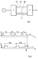
- the reference numeral 1 is a transducer, in particular in the form of a digital encoder or the like. Played.
- This transducer 1 stands with a transmitter station 2 acting as an evaluation unit in operative connection, so that the im Sensor 1 formed signals there after a A / D conversion can be prepared for forwarding.
- the one designed as an evaluation unit Transmitting station 2 is via a number of parallel signal lines S.1 to S.N with an as Control trained receiving station 3 connected.
- the delivered by the transducer 1 and measured value signals processed in the transmitting station become like a parallel bus on the signal lines S.1 to S.N by simultaneously applying the corresponding Level on the lines to the receiving station 3, which in particular as a controller trained, forwarded.
- a validity signal (Valid) provided.
- the receiving station 3 which is designed as a controller, accepts this on the signal lines S.1 to S.N present levels in the corresponding input memory for forwarding or conversion of the data.
- FIG. 2 shows the course of time over the axis t of the signal V, that is to say that of the transmitting station 2 formed valid signal for taking over those present on the signal lines S.1 to S.N. Data.
- Figure 2 is below the signal curve of the valid signal V also over the time axis t, the readiness to receive represented by the reference symbol E. the receiving station 3 shown in FIG. 1.
- Due to in the receiving station 3, which is designed, for example, as a control of the machine, processes running the receiving station 3 is separated from one another by time segments TE.1, TE.2 etc.
- Phases of readiness to receive. 2 is essential thereby that the readiness to receive E of the receiving station 3, which is not at level 0 ready to receive and ready to receive at level 1, irregular or unpredictable Times.
- the time rate of the transmission of the signals on the signal lines S.1 to S.N and thus also the sending of the signal V is not constant, but within a predetermined bandwidth between a maximum and a minimum value.
- this is done by correspondingly setting an in the transmitter station 2 existing timers or a specially provided random generator.
- the irregular time intervals by which the transmitting station 2 transmits data to the receiving stations 3 separately on the signal lines S.1 to SN ensures that the receiving station 3 can receive data during the phase of the readiness to receive E after a finite number of sending processes.
- the reference symbol t E represents that point in time at which a transmission process of the transmission station 2 on the signal lines S.1 to SN with the associated valid signal V enters a phase of the readiness for reception E of the reception station 3.
- the signals from the transmitting station 2 on the signal lines S.1 to SN are transferred to the corresponding drivers and downstream processing stages of the receiving station 3.
Landscapes
- Arrangements For Transmission Of Measured Signals (AREA)
- Communication Control (AREA)
- Accessory Devices And Overall Control Thereof (AREA)
Description
- Fig. 1
- prinzipiell der Übertragungskanal zwischen einer Sendestation und einer Empfangsstation, und
- Fig. 2
- den Signalverlauf des Signals V gegenüber der Empfangsbereitschaft E der Empfangsstation gemäß Fig. 1.
- 1
- Meßwertaufnehmer
- 2
- Sendestation (Auswerteeinheit)
- 3
- Empfangsstation (Steuerung)
- S.1-S.N
- Signalleitung
- V
- Leitung Gültigkeitssignal (Valid-Signal, Sendevorgang Station 2)
- E
- Empfangsbereitschaft (Empfangsstation 3)
- T.1, T.2,
- Zeitabstand Sendevorgang (Valid-Signal V)
- TE.1, TE.2,
- Zeitabstand Empfangsbereitschaft (Empfangsstation)
Claims (8)
- Verfahren zur Datenübertragung innerhalb einer Druckmaschine zwischen einer Sendestation und einer mit dieser über ein einkanaliges Übertragungsmedium verbundenen Empfangsstation, wobei zwischen Sendestation und Empfangsstation zumindest außerhalb der Sendezeiten keinerlei zeitliche Synchronisation erfolgt,
dadurch gekennzeichnet,
daß aufeinanderfolgende Sendevorgänge durch in der Länge unterschiedliche Zeitabstände voneinander getrennt werden. - Verfahren nach Anspruch 1,
dadurch gekennzeichnet,
daß bei einer auf einer Anzahl von Signalleitungen erfolgenden parallelen Datenübertragung die Zeitabstände (T.1, T.2, ....) zwischen zwei Sendevorgängen innerhalb eines vorgegebenen Zeitrahmens ständig variiert werden. - Verfahren nach Anspruch 1,
dadurch gekennzeichnet,
daß bei einer seriellen Datenübertragung die Zeitabstände zwischen einer zuletzt auf dem Übertragungskanal angelegten Information und einer nächsten Information (Datenblock) variiert wird. - Verfahren nach einem der vorhergehenden Ansprüche,
dadurch gekennzeichnet,
daß die Zeitraten zum Senden von Daten bzw. die zwischen zwei aufeinanderfolgenden Sendevorgängen vorgesehenen Zeitintervalle durch einen Zufallsgenerator vorgegeben werden. - Verfahren nach einem der vorhergehenden Ansprüche 1 bis 3,
dadurch gekennzeichnet,
daß zur Variation der Zeitrate zum Senden von Daten bzw. der zwischen zwei aufeinanderfolgenden Sendevorgängen vorgesehenen Zeitintervalle durch Setzen eines in der Sendestation vorgesehenen Timers erfolgt. - Vorrichtung zur Durchführung des Verfahrens nach einem der Ansprüche 1 bis 5, wobei zwischen einer Sendestation und einer mit dieser über ein einkanaliges Übertragungsmedium verbundenen Empfangsstation Daten unidirektional und asynchron übertragbar sind,
dadurch gekennzeichnet,
daß durch die Sendestation (2) auf den zwischen der Sendestation (2) und der Empfangsstation (3) zur Datenübertragung vorgesehenen Übertragungskanal (Signalleitung S.1 - S.N, Valid-Signal V) aufeinanderfolgende Daten mit jeweils wechselnder Zeitrate übertragbar sind. - Vorrichtung nach Anspruch 6,
dadurch gekennzeichnet,
daß zwischen der Sendestation (2) und der Empfangsstation (3) über eine Anzahl von Signalleitungen (S.1 - S.N) Parallelsignale übertragbar sind und die zur Übernahme in der Empfangsstation (3) übertragenen Valid-Signale (V) jeweils durch unregelmäßige Zeitabstände (T.1, T.2, .....) voneinander getrennt übertragbar sind. - Vorrichtung nach Anspruch 6,
dadurch gekennzeichnet,
daß bei einer zwischen der Sendestation (2) und der Empfangsstation (3) als serieller Übertragungskanal ausgebildeten Übertragungsmedium durch die Sendestation (2) nachfolgende Informationsblöcke (Daten) jeweils durch wechselnde Zeitabstände voneinander getrennt übertragbar sind.
Applications Claiming Priority (2)
| Application Number | Priority Date | Filing Date | Title |
|---|---|---|---|
| DE19613289A DE19613289C1 (de) | 1996-04-03 | 1996-04-03 | Verfahren und Vorrichtung zur Übertragung von Daten innerhalb einer Druckmaschine |
| DE19613289 | 1996-04-03 |
Publications (2)
| Publication Number | Publication Date |
|---|---|
| EP0799696A1 EP0799696A1 (de) | 1997-10-08 |
| EP0799696B1 true EP0799696B1 (de) | 1999-11-03 |
Family
ID=7790345
Family Applications (1)
| Application Number | Title | Priority Date | Filing Date |
|---|---|---|---|
| EP97104448A Expired - Lifetime EP0799696B1 (de) | 1996-04-03 | 1997-03-15 | Verfahren und Vorrichtung zur Übertragung von Daten innerhalb einer Druckmaschine |
Country Status (3)
| Country | Link |
|---|---|
| EP (1) | EP0799696B1 (de) |
| AT (1) | ATE186255T1 (de) |
| DE (2) | DE19613289C1 (de) |
Family Cites Families (4)
| Publication number | Priority date | Publication date | Assignee | Title |
|---|---|---|---|---|
| DE3720272A1 (de) * | 1987-06-19 | 1988-12-29 | Heidelberger Druckmasch Ag | Prozessorgesteuerte dateneingabe- und -ausgabeeinrichtung |
| DE3839248A1 (de) * | 1988-11-21 | 1990-05-23 | Roland Man Druckmasch | Dezentraler steuerrechner, insbesondere innerhalb einer rotationsdruckmaschine, der ueber einen bus mit mehreren peripheren einheiten verbunden ist |
| DE4129373C2 (de) * | 1991-09-04 | 1995-05-18 | Roland Man Druckmasch | Vorrichtung zur Passerverstellung an einem Plattenzylinder einer Druckmaschine |
| DE4207305C2 (de) * | 1992-03-07 | 1996-09-19 | Heidelberger Druckmasch Ag | Vorrichtung zur Steuerung des Stapelträgers in Druckmaschinen |
-
1996
- 1996-04-03 DE DE19613289A patent/DE19613289C1/de not_active Expired - Fee Related
-
1997
- 1997-03-15 DE DE59700645T patent/DE59700645D1/de not_active Expired - Fee Related
- 1997-03-15 AT AT97104448T patent/ATE186255T1/de not_active IP Right Cessation
- 1997-03-15 EP EP97104448A patent/EP0799696B1/de not_active Expired - Lifetime
Also Published As
| Publication number | Publication date |
|---|---|
| ATE186255T1 (de) | 1999-11-15 |
| DE19613289C1 (de) | 1997-10-09 |
| DE59700645D1 (de) | 1999-12-09 |
| EP0799696A1 (de) | 1997-10-08 |
Similar Documents
| Publication | Publication Date | Title |
|---|---|---|
| DE4342377B4 (de) | Anordnung und Verfahren zur seriellen Datenübertragung einer Positionsmeßeinrichtung | |
| EP0790489B1 (de) | Vorrichtung und Verfahren zur Umschaltung zwischen verschiedenen Betriebsmodi eines Messwertaufnehmers | |
| WO2002076033A2 (de) | Synchrones, getaktetes kommunikationssystem mit dezentralen ein-/ausgabe-baugruppen und verfahren zur einbindung dezentraler ein-/ausgabe-baugruppen in ein solches system | |
| DE102008008602A1 (de) | Transfervorrichtung für Werkstückträger | |
| EP1168120B1 (de) | Verfahren und Vorrichtung zur seriellen Datenübertragung zwischen einem Positionsmesssystem und einer Verarbeitungseinheit | |
| DE3900924C2 (de) | Verfahren zum Steuern mehrerer, in Reihe angeordneter Druckwerke und Druckmaschinen zum Bedrucken von Bahnabschnitten | |
| EP0829352A2 (de) | Diagnosesystem | |
| EP0747216B1 (de) | Steuerung für eine Druckmaschine | |
| EP3001627A1 (de) | Verfahren und vorrichtung zur seriellen datenübertragung über einen bidirektionalen datenübertragungskanal | |
| EP1393082A1 (de) | Raddrehzahlsensoranordnung mit übertragung von zusatzinformationen | |
| EP1125406B1 (de) | Verfahren und vorrichtung zum aufbereiten eines empfangenen signals, das daten codiert übermittelt | |
| EP0370223A2 (de) | Dezentraler Steuerrechner, insbesondere innerhalb einer Rotationsdruckmaschine, der über einen Bus mit mehreren peripheren Einheiten verbunden ist | |
| WO2009074545A2 (de) | Vorrichtung zur übertragung von elektrischer energie und information | |
| DE10335862B4 (de) | Verfahren zum Kalibrieren eines inkrementalen Winkelgebers an einem rotierenden Bauteil | |
| DE3300218C2 (de) | Datenfernübertragungssystem | |
| EP0799696A1 (de) | Verfahren und Vorrichtung zur Übertragung von Daten innerhalb einer Druckmaschine | |
| EP2746892B1 (de) | Automatisierte Anlage und Verfahren zur Synchronisation einer automatisierten Anlage | |
| DE3914831C2 (de) | ||
| DE102009032229A1 (de) | Verfahren und Einrichtung zur Protokollierung von Prozessvariablen eines digitalen Feldgerätes | |
| EP0694387B1 (de) | Verfahren und Vorrichtung zur Zustandsüberwachung einer umstellbaren Bogendruckmaschine | |
| EP0747215B1 (de) | Steuerung für eine Druckmaschine | |
| DE3318575A1 (de) | Verfahren und einrichtung zur auffahrsicherung bei automatisierten fahrzeugsystemen | |
| DE2846129C2 (de) | Informationsübertragungseinrichtung | |
| EP1067497B1 (de) | Verfahren zur seriellen Übertragung von digitalen Messdaten | |
| EP2850396B1 (de) | Verfahren zur informationsübermittelung und vorrichtung zur ausführung des verfahrens |
Legal Events
| Date | Code | Title | Description |
|---|---|---|---|
| PUAI | Public reference made under article 153(3) epc to a published international application that has entered the european phase |
Free format text: ORIGINAL CODE: 0009012 |
|
| 17P | Request for examination filed |
Effective date: 19970326 |
|
| AK | Designated contracting states |
Kind code of ref document: A1 Designated state(s): AT CH DE FR GB IT LI NL |
|
| GRAG | Despatch of communication of intention to grant |
Free format text: ORIGINAL CODE: EPIDOS AGRA |
|
| GRAG | Despatch of communication of intention to grant |
Free format text: ORIGINAL CODE: EPIDOS AGRA |
|
| GRAH | Despatch of communication of intention to grant a patent |
Free format text: ORIGINAL CODE: EPIDOS IGRA |
|
| GRAH | Despatch of communication of intention to grant a patent |
Free format text: ORIGINAL CODE: EPIDOS IGRA |
|
| 17Q | First examination report despatched |
Effective date: 19990423 |
|
| ITF | It: translation for a ep patent filed | ||
| GRAA | (expected) grant |
Free format text: ORIGINAL CODE: 0009210 |
|
| AK | Designated contracting states |
Kind code of ref document: B1 Designated state(s): AT CH DE FR GB IT LI NL |
|
| REF | Corresponds to: |
Ref document number: 186255 Country of ref document: AT Date of ref document: 19991115 Kind code of ref document: T |
|
| ET | Fr: translation filed | ||
| REG | Reference to a national code |
Ref country code: CH Ref legal event code: EP |
|
| GBT | Gb: translation of ep patent filed (gb section 77(6)(a)/1977) |
Effective date: 19991103 |
|
| REG | Reference to a national code |
Ref country code: CH Ref legal event code: NV Representative=s name: E. BLUM & CO. PATENTANWAELTE |
|
| REF | Corresponds to: |
Ref document number: 59700645 Country of ref document: DE Date of ref document: 19991209 |
|
| PLBE | No opposition filed within time limit |
Free format text: ORIGINAL CODE: 0009261 |
|
| STAA | Information on the status of an ep patent application or granted ep patent |
Free format text: STATUS: NO OPPOSITION FILED WITHIN TIME LIMIT |
|
| 26N | No opposition filed | ||
| PGFP | Annual fee paid to national office [announced via postgrant information from national office to epo] |
Ref country code: CH Payment date: 20010219 Year of fee payment: 5 |
|
| PGFP | Annual fee paid to national office [announced via postgrant information from national office to epo] |
Ref country code: AT Payment date: 20010226 Year of fee payment: 5 |
|
| PGFP | Annual fee paid to national office [announced via postgrant information from national office to epo] |
Ref country code: NL Payment date: 20010228 Year of fee payment: 5 |
|
| REG | Reference to a national code |
Ref country code: GB Ref legal event code: IF02 |
|
| PG25 | Lapsed in a contracting state [announced via postgrant information from national office to epo] |
Ref country code: AT Free format text: LAPSE BECAUSE OF NON-PAYMENT OF DUE FEES Effective date: 20020315 |
|
| PG25 | Lapsed in a contracting state [announced via postgrant information from national office to epo] |
Ref country code: LI Free format text: LAPSE BECAUSE OF NON-PAYMENT OF DUE FEES Effective date: 20020331 Ref country code: CH Free format text: LAPSE BECAUSE OF NON-PAYMENT OF DUE FEES Effective date: 20020331 |
|
| PG25 | Lapsed in a contracting state [announced via postgrant information from national office to epo] |
Ref country code: NL Free format text: LAPSE BECAUSE OF NON-PAYMENT OF DUE FEES Effective date: 20021001 |
|
| REG | Reference to a national code |
Ref country code: CH Ref legal event code: PL |
|
| NLV4 | Nl: lapsed or anulled due to non-payment of the annual fee |
Effective date: 20021001 |
|
| PGFP | Annual fee paid to national office [announced via postgrant information from national office to epo] |
Ref country code: GB Payment date: 20030226 Year of fee payment: 7 |
|
| PGFP | Annual fee paid to national office [announced via postgrant information from national office to epo] |
Ref country code: DE Payment date: 20030311 Year of fee payment: 7 |
|
| PGFP | Annual fee paid to national office [announced via postgrant information from national office to epo] |
Ref country code: FR Payment date: 20030314 Year of fee payment: 7 |
|
| PG25 | Lapsed in a contracting state [announced via postgrant information from national office to epo] |
Ref country code: GB Free format text: LAPSE BECAUSE OF NON-PAYMENT OF DUE FEES Effective date: 20040315 |
|
| PG25 | Lapsed in a contracting state [announced via postgrant information from national office to epo] |
Ref country code: DE Free format text: LAPSE BECAUSE OF NON-PAYMENT OF DUE FEES Effective date: 20041001 |
|
| GBPC | Gb: european patent ceased through non-payment of renewal fee |
Effective date: 20040315 |
|
| PG25 | Lapsed in a contracting state [announced via postgrant information from national office to epo] |
Ref country code: FR Free format text: LAPSE BECAUSE OF NON-PAYMENT OF DUE FEES Effective date: 20041130 |
|
| REG | Reference to a national code |
Ref country code: FR Ref legal event code: ST |
|
| PG25 | Lapsed in a contracting state [announced via postgrant information from national office to epo] |
Ref country code: IT Free format text: LAPSE BECAUSE OF NON-PAYMENT OF DUE FEES;WARNING: LAPSES OF ITALIAN PATENTS WITH EFFECTIVE DATE BEFORE 2007 MAY HAVE OCCURRED AT ANY TIME BEFORE 2007. THE CORRECT EFFECTIVE DATE MAY BE DIFFERENT FROM THE ONE RECORDED. Effective date: 20050315 |