EP0799466B1 - Verfahren zur darstellung von objekten mit hilfe einer bildwiedergabeeinrichtung - Google Patents
Verfahren zur darstellung von objekten mit hilfe einer bildwiedergabeeinrichtung Download PDFInfo
- Publication number
- EP0799466B1 EP0799466B1 EP95942044A EP95942044A EP0799466B1 EP 0799466 B1 EP0799466 B1 EP 0799466B1 EP 95942044 A EP95942044 A EP 95942044A EP 95942044 A EP95942044 A EP 95942044A EP 0799466 B1 EP0799466 B1 EP 0799466B1
- Authority
- EP
- European Patent Office
- Prior art keywords
- memory
- coordinates
- data
- image
- line
- Prior art date
- Legal status (The legal status is an assumption and is not a legal conclusion. Google has not performed a legal analysis and makes no representation as to the accuracy of the status listed.)
- Expired - Lifetime
Links
Images



Classifications
-
- G—PHYSICS
- G09—EDUCATION; CRYPTOGRAPHY; DISPLAY; ADVERTISING; SEALS
- G09G—ARRANGEMENTS OR CIRCUITS FOR CONTROL OF INDICATING DEVICES USING STATIC MEANS TO PRESENT VARIABLE INFORMATION
- G09G5/00—Control arrangements or circuits for visual indicators common to cathode-ray tube indicators and other visual indicators
- G09G5/36—Control arrangements or circuits for visual indicators common to cathode-ray tube indicators and other visual indicators characterised by the display of a graphic pattern, e.g. using an all-points-addressable [APA] memory
-
- G—PHYSICS
- G09—EDUCATION; CRYPTOGRAPHY; DISPLAY; ADVERTISING; SEALS
- G09G—ARRANGEMENTS OR CIRCUITS FOR CONTROL OF INDICATING DEVICES USING STATIC MEANS TO PRESENT VARIABLE INFORMATION
- G09G5/00—Control arrangements or circuits for visual indicators common to cathode-ray tube indicators and other visual indicators
- G09G5/36—Control arrangements or circuits for visual indicators common to cathode-ray tube indicators and other visual indicators characterised by the display of a graphic pattern, e.g. using an all-points-addressable [APA] memory
- G09G5/39—Control of the bit-mapped memory
- G09G5/395—Arrangements specially adapted for transferring the contents of the bit-mapped memory to the screen
-
- G—PHYSICS
- G09—EDUCATION; CRYPTOGRAPHY; DISPLAY; ADVERTISING; SEALS
- G09G—ARRANGEMENTS OR CIRCUITS FOR CONTROL OF INDICATING DEVICES USING STATIC MEANS TO PRESENT VARIABLE INFORMATION
- G09G5/00—Control arrangements or circuits for visual indicators common to cathode-ray tube indicators and other visual indicators
- G09G5/02—Control arrangements or circuits for visual indicators common to cathode-ray tube indicators and other visual indicators characterised by the way in which colour is displayed
- G09G5/022—Control arrangements or circuits for visual indicators common to cathode-ray tube indicators and other visual indicators characterised by the way in which colour is displayed using memory planes
Definitions
- the invention relates to a method for representing Objects with the aid of an image display device.
- Image display devices are becoming increasingly popular Presentation of information used in the form of Data are available and by means of the so-called Computer graphics made visible as flat objects become. For example, for airplanes Display devices have become known in which on a Various symbols are displayed on the screen the most important for the pilot Show information. Such an ad is described for example in EP 0 418 558 B2.
- the can be both areal and line-like Preparation of the graphic data before the registration in the Image storage requires considerable computing effort. So For example, all objects involved are new calculate if an object is beyond limits of one or moved several other objects. This is all the higher To provide computing power the faster Changes should be made.
- the object of the present invention is to provide a method for Representation of objects with the help of a Specify image display device in which a greatest possible variety of representations and a high one Rate of change with a given computing power possible are.
- This object is achieved in that data, which describe the shape and location of the objects and stored in at least one image memory that further data describing colors are supplied and in which exactly one color is assigned to each object extends over the entire object, at least one further memory can be written that the data describing the form and location from the minimum an image memory read out line by line and as addresses which are supplied with at least one further memory and that the further data under the addresses from the at least read out another memory as digital video signals which are fed to the image display device.
- Processing to video signals is preferably done in that the further properties of the objects descriptive further data in at least one further Memories that are written in the shape and location Descriptive read out data as addresses to the minimum another memory are supplied and that the other Data among the addresses from the at least one more Memory can be read out as digital video signals.
- the digital video signals are supplied with other digital video signals are mixed.
- the representation generated with the inventive method objects have a background.
- This can for example, be a map, the ones to be displayed Objects flight information, such as radio beacons, Air corridors, aircraft symbols and alphanumeric information, could be.
- the additional digital video signals supplied can also be used with another device after method according to the invention are generated. That's the way it is for example possible with a first device symbols, Generate scales and pointers and use them as Background signal generated with a second device Image to highlight a landscape or more imaging units for overlaying various types Cascade symbolism.
- Another development of the method according to the invention is that data that the shape and location of describe linear objects in a first Image storage and data showing the shape and location of describe areal objects in a second Image storage are stored and that from the Image data read out as addresses each one first and a second further memory are supplied. This is one adapted to the respective requirements different treatment of flat and linear Objects possible.
- the data describing the shape and location include several binary digits per picture element and that each a binary digit of a display level, especially one object to be displayed in this display level, assigned. It is preferably provided that in the at least one additional memory under one each Address the color and transparency of an object or one Combination of several overlapping objects be filed. A quick change in presentation individual objects or combinations of objects with respect to Color and transparency is possible because the others Data can be fed into each address independently and in the additional memories can be saved.
- any colors can be assigned. These can also be used during the representation, for example, can be changed. This can be done in the method according to the invention, without the graphics processor the object as such - the means, whose shape and location - needs to be recalculated.
- the lines in terms of color and priority required the lines in terms of color and priority to adapt to the other objects. For example required to break a line if it is partial lies behind a non-transparent areal object.
- Such adjustments are in the inventive
- the method can be achieved in an advantageous manner in that the the data describing the shape and location of several image elements Binary digits include that one binary digit each Presentation level, especially one in this Display level object to be displayed is assigned that the first further memory removable signals that the Specify the level of the respective linear object with the Data read from the second image memory compared and that the digital representing the lines Video signals through digital video signals what objects represent for those picture elements to be replaced at which the comparison shows that a line behind one Object runs.
- Another advantageous embodiment of this training consists in deriving the coordinates for one Circulation around the object along the contour one after the other supplied data, which contain the contour that the coordinates (X, Y) for three successive clock periods are buffered, that two successive and two by two Clock periods with each other delayed coordinates with each other be compared and that by logical connection of the Comparison results Instructions for changing, not changing or Set coordinates previously stored in the first memory be generated.
- the graphics generator that supplies it generates the coordinates already in the through the address space of the image memory given grid.
- a graphic generator available on the market use, whose resolution is greater than that by the Image memory and the image display device given Resolution is so that, for example, the fed Coordinates have ten binary positions compared to eight Binary digits ultimately through the frame buffer specified coordinates. Then it can happen that the coordinates (based on the image memory) of one Do not change output to the following.
- Preventing misinterpretation is according to another Training provided that a forwarding of Caching only takes place if it is different from Clock period to clock period at least one of the coordinates changes.
- the coordinates are stored in that under a the address representing the respective line the coordinates two picture elements are stored.
- the method according to the invention can be used to display a or several objects in one layer and with one color be applied. With the method according to the invention but also the representation of objects in several levels possible. In the case of the other embodiment then only a one-bit wide image memory for each level and a memory for the color according to the desired one Color resolution required. Since digital modules are often used Processing of eight bit wide signals are designed eight levels can be processed particularly cheaply. This means that practically all applications can be covered become.
- X1, Y1 mean the following coordinates, X2, Y2 the current coordinates and X3, Y3 the previous ones Coordinates.
- This embodiment is even very complicated Object shapes ensures that a even number of 1-bit signals occur. Such complicated shapes are present, for example, when a Object has a point or constrictions.
- bit widths of the individual specified below Signals have been carried out in a practical way device according to the invention as advantageous exposed. Depending on the requirements in detail and Possibilities of the technology used in each case can other bit widths and signal formats can also be selected.
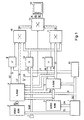
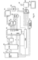
- Fig. 1 In the device according to Fig. 1 generates an in itself known graphics processor graphics data DL and DA, which Affect lines and areas. Furthermore, from Graphics processor 1 generates control data DC that later to be discribed. With the data DL, DA is a Video read / write memory (video RAM) 2, 3 loaded. Such video memories are for storing the for one image each specific data and line by line Reading trained. Are common with video stores Two memories are provided, which are loaded alternately and be read out. Because such video memory including the associated control circuits as Components are available, a description is unnecessary the video memory 2, 3 in detail.
- video RAM Video read / write memory
- the device When using the video memory 3 under the However, the device according to the invention Peculiarity in that one of the binary digits of the stored data in one level areal object is assigned. For such an object is only the presence in the video memory pro Image element or the spatial extent filed - not however, its attribute such as color or transparency. Colour, Transparency and, where appropriate, intensity are discussed in following also for the sake of simplicity as a property of a Area or line.
- the Video memory 3 With the from the Video memory 3 read eight-bit signals RA can each have two-dimensional objects in eight different levels.
- a special one advantageous method for generating the signals RA for the Areas is in the German patent application P 44 46 783.4 described.
- the signals RL and RA for the lines and the areas are each a read / write memory 4, 5 supplied. This are in the drawing because of their assignment to the lines or areas designated with L-RAM and A-RAM, the However, in the description, for the sake of simplicity, memory 4 and Memory 5 called.
- memories 4 and 5 there are one under each address Line color LC or a surface color AC and a Line factor LF or an area factor AF filed.
- the memory 4 contains one for each address Line intensity LI.
- the content of the two memories 4, 5 can from the graphics processor 1 depending on the requirements in individual for an operational phase as a whole or figuratively via a data bus 6 carrying the control data DC become.
- the signals RL contain the in binary coded form Information as to which of the colors stored in the memory 4 should receive the respective linear object. Further the signals RL contain intensity information which is used for later suppression of alias interference are required.
- the memory 5 is a varied variation of the Representation of areal objects by the RA signals are possible.
- the Color of areal objects that are not related to others Objects overlap, can be set arbitrarily.
- the signals RA have a 1 only in a binary position on. At this address, a any color and any factor can be stored, which are assigned to the respective object.
- the dimming circuits 8, 9 and a further dimming circuit 14 consist essentially of a multiplier, the Line factor LF, the area factor AF and that at 7 supplied background signal MAP with one dimming factor each multiplied, the dimming factors for the line factor and the area factor in the illustrated embodiment are the same, but can also be different.
- the Dimming factors are determined by the graphics processor 1 via the Bus system 6 written in a dimming register 15. Thereby, that not the line color LC or the area color AC, but the corresponding factors with the dimming factors can be multiplied, a control of the brightness of the reproduced image can be made without the entire image impression falsified and thus the recognizability of the individual objects is reduced.
- the eight bit wide data RL (Fig. 1) from the Video memory 2 in five bit wide data RMC and three bit split wide data RMI.
- C means color and I intensity.
- the binary digits representing the color RMC will have 21 address inputs from four via input Read / write memories 22, 23, 24, 25 are supplied.
- the the Binary digits representing intensity reach RMI an input 26 to address inputs of another Read / write memory 27.
- Read / write memory 22 to 25 and 27 can via the data bus 6 (Fig. 1) from Graphics processor 1 with those for the respective lines provided properties are loaded.
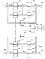
- the memory arrangement shown in FIG. 2 also contains a multiplexer control circuit 28 which is derived from the signal RA from the video memory 3 (FIG. 1) via an input 29 is controlled. Details of the multiplexer control circuit 28 are explained in FIG. 3. For every value at 21 supplied data RMC in the memory 22 is wider than 15 bits Value a line color and in memory 23 a six bit broader value stored as a line factor. In addition, the Memory 24 for each value of RMC a bit LT indicating whether the line in question is shown transparently per se shall be. In the memory 25 is RMC for each value filed a priority that states in which order the respective line between foreground and background should be displayed. This four bit wide signal LP and the one bit wide signal LT become the Multiplexer control circuit 28 fed.
- the three bit wide signal RMI is used to get out of memory 27 read out the signal LI (line intensity). This points a maximum in the middle of the lines and increases to the Edges off. Through the cross-fading between line and surface or background in the crossfader 12 Alias interference suppressed.
- a third multiplexer 36 serves the line intensity LI to be replaced by the value 0, which is also from the Multiplexer control circuit 28 is controlled. At exit 37 the signal LI is removable.
- the further signal AD read from table 44 takes the value 1 if there is an object in at least one level is available.
- the output 47 of the AND circuit carries a signal SACF, which controls the multiplexers 30, 31 (FIG. 2) in such a way that at the value 1 of the signal SACF from the multiplexers 30, 31 the signals AC and AF, ie the properties of the surface as signals LC and LF to the outputs 34, 35 (FIG. 2) of the Lines memory are routed.
- With the help of And circuit 46 given condition is that there must be a surface at all that the line is under the most forward area and that the Signal LT indicates transparency.
- a signal SOI derived taken from the exit 49 and the Multiplexer 36 (Fig. 2) is supplied.
- This signal causes the signal LI (line intensity) to be set to zero. It is generated by the AND operation at 48 (equal to 1 set), if there is any surface at all, if the respective line under the most forward area and if the surface is not transparent. The latter is the signal LT via an inverter 50 AND circuit 48 supplied.
- the TL signal denotes the highest priority level in which there is an area. For example, to that considered time or on the considered picture element if there is no area, all binary positions of the signal are RA and the signals TL and AD equal 0. It is for example, in the foremost level, through the Binary position (7) of the signal RA is shown, a Area, the signal is TL 1000 and the signal AD is 1. It is then irrelevant whether in the lower levels Areas are available, which is indicated by an X in the table is shown.
- Fig. 5 shows to illustrate the function of the Memory 5 (Fig. 1) is a table, the excerpt Represents the content of the memory.
- Fig. 4 serve as input variables or addresses Binary positions of the signal RA, so that a total of 256 Storage locations or lines of those shown in FIG. 5 Table are stored.
- the 12 binary digits of the AC signal are in three color values R, G, B like red, green and blue divided up.
- the memory 5 is designed as a read / write memory, that via the data bus 6 (FIG. 1) at the addresses RA any data can be fed. This can for example during the vertical frequency Blanking intervals happen so that the properties of objects can change almost continuously. It is however, it is also possible to reload the memory 5, when certain operating modes are set.
- Row a of the table shown in Fig. 5 represents the case of an object in the foremost level, to which the color red is assigned. In the other levels there are no objects.
- line b the case is one green object shown in level 2 while the line c shows an object on the third level, whose color is both has red as well as green parts.
- the signal AF is a measure of the transparency of each entire object represented by the signal AC.
- Maximum value 1111 is no transparency, for example in lines b and e.
- the objects according to lines a, c and However, d are moderately transparent. All entries of the The tables can be programmed independently of each other. So can for example another mixed color (R, G, B in row d) be loaded without the colors of the objects themselves be changed.
- Fig. 6 shows the crossfader 12 (Fig. 1) in more detail Presentation.
- For each color value signal R, G, B is a Crossfader 51, 52, 53 provided. Entrances 54, 55, 56 the six bit wide output signals of the Crossfader 10 (Fig. 1) fed.
- the inputs 57, 58, 59 receive six binary digits wide output signals the crossfader 11.
- Registers 61 to 66 are pairs of these signals, which refer to the same color, with a clock Clk in one of the crossfaders registered.
- Another register 60 is used for Buffering and writing the line intensity LI via the entrance 67.
- Each of the crossfaders 51, 52, 53 consists essentially of two multipliers 68, 69, which on the one hand have one of the input signals and on the other hand the inverted or non-inverted signal LI is forwarded. This is the one input signal with LI and the other input signal with one's complement multiplied by LI.
- the output signals of the multipliers 68, 69 arrive at an adder 70, the output 71, 72, 73 carries the signal R, G and B, respectively.
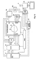
- a graphics generator 81 provided the coordinates X, Y of the points on the Contour of an object to be displayed is calculated and issues one after the other.
- data C is output, which are valid for the entire object and the color of the Describe the object.
- an image display device 82 which is periodically on writes a line-shaped raster is an image memory 83 provided, which is called contour storage in the following.
- the address space of this contour memory reflects that raster structure of the picture again with Ymax lines and Xmax picture elements per line.
- the image memory 83 has ADDR inputs for addresses for writing and writing Read, a data input DI and a data output DO.
- contour memory 83 One bit can be found in the contour memory 83 under each address be filed. To play an object 85 those picture elements that have the contour 84 of the object 85 form, set to the value "1" corresponding to that of the Graphics generator 81 generated coordinates X, Y while the other picture elements have the value "0". Then the Contour memory 83 read out in rows, for which addresses x, y are supplied by an address generator 86.
- a Timer circuit 97 ensures the timing of the individual functions, especially the writing and Reading processes in the contour memory 83.
- a filter circuit 95 is provided, which from the supplied coordinates X, Y signals A and B are derived. This are fed to a logic circuit 96 which is connected to a Output and an input of the contour memory is connected. Reading for one picture element is thereby Modify and rewrite what's under the The term read-modify-write has become known.
- the graphics generator 81 then begins with the Output of coordinates X, Y, from which, on the one hand, the addresses X, Y derived and on the other hand in the filter circuit 95 the signals A and B are generated. This can be done with the help the logic circuit 96 the respective addressed picture element leave unchanged, invert or to "0" (reset) or set to "1” (set). During these processes, a Generation of rectangular pulses at the output 92 of the D flip-flops 91 can be prevented by the Timer circuit of the data input of the D flip-flop 91 "0" is set.
- Fig. 8 shows the filter circuit 95, the 101 and 102 Coordinates X and Y from the graphics generator 1 (Fig. 7) supplied become.
- the coordinate X is clocked using two Registers 103, 104 each delayed by one clock period, see above that received three consecutively at the same time X coordinates X1, X2, X3 are available.
- the same way are the Y coordinates using registers 105, 106 Y1, Y2, Y3 generated.
- X1, X2 and X3 are each in pairs compared with one another in comparators 107, 108, 109.
- On The corresponding comparison of the Y components is carried out with the help of comparators 110, 111, 112.
- Each of the comparators generates output signals which characterize three states, namely that the signals at its inputs are the same and that the first signal or that the second signal is larger than the other signal.
- These output signals are fed to a logic circuit 113 which, in accordance with the truth table shown above, forms instructions for deriving the 1-bit signals - starting from a contour memory whose content is set to "0".
- Signals A and B are generated, which are encoded as follows, for example: Instruction A B do not invert (NI) 0 0 invert (I) 1 0 put (S) 1 1 reset (R) 0 1
- the signals A and B are converted using a register 114 delayed one clock period and via an output 115 of the Logic circuit 96 (Fig. 7) is supplied. At other exits 116, 117 the associated coordinates X, Y are removable. Due to the delay with the help of register 114, the Signals at output 115 in the time plane of coordinates X2, Y2. In relation to a picture element with these Coordinates represent the coordinates X1, Y1 each previous and the coordinates X3, Y3 each following picture element.
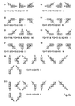
- FIGS. 9a and 9b presented and summarized in case groups for which the same condition applies or the same Output signals of the comparators (Fig. 8) are present.
- the Representations lie around the object in the Clockwise. With italic digits 1, 2, 3 the future, the present and the respective denoted previous picture element.
- the cases in group G1 concern inner corners on the right edge of the object.
- the object area is therefore on the left or below of the picture elements shown. That in each case the picture element lying in the corner is not inverted, the means that there is no 1-bit signal at these coordinates saved. It must be assumed that on the left Edge of the object already in the same line 1-bit signal is present or is still being generated. That still remaining 1-bit signal to identify the right one However, the edge cannot lie on this inner corner, because the contour continues to the right.
- the cases in group G2 each represent one at the bottom right lying outside corner, for which a 1-bit signal is set must become. The same applies to the one on the top left Outside corner according to group G3.
- Groups G4 and G5 in turn affect inner corners, namely on the left side of the object. No 1-bit signal is generated at these corners, that is, the ones previously written into the memory Zeros are not inverted.
- the groups G6 and G7 in turn refer to outside corners, namely those on left and right edges of the object so that a The picture element is inverted.
- the cases of the group G8 are again inside corners where there is no inversion is made.
- contour memory 121 is provided, in which one address spanning several bits Information can be filed.
- contour memory 121 has contour memory 121 several levels up. Because often in digital technology Eight-bit words (bytes) are used with memory Eight levels easily realized or available. In order to can the contours of eight different objects in the Contour memory 121 are stored, the colors of these Objects stored in an eight-fold color memory 122 can be.
- the requirements in individual cases can also be more or less than eight levels are provided. 10 are For the sake of clarity, only three levels are indicated. A logic circuit 123 and flip-flops 124 are corresponding the number of levels executed multiple times. A single on the arrow pointing at the middle level means that signals be fed to all levels. Are for the individual levels different signals determined, are several arrows shown that point to different levels.
- the inscription of the contours of the individual objects in the Contour memory 121 takes place sequentially, for which purpose Graphics generator during a time when the coordinates X, Y and the color C output for a first object logic circuit 123 is controlled such that a change in the 1-bit signals in the Read-Modify-Write cycle only in that bit of one under the address corresponding to the coordinates from the Contour memory 121 read bytes is made that belongs to the level of the respective object.
- the contour of an object in the associated level of the memory 121 registered is carried out by the graphics generator 81 Data output for the second object, where then in the Logic circuit 123 only those belonging to the second object Bits are processed.
- the contours are read out in such a way that in each case an address x, y read out the entire byte and point it to the Inputs of the flip-flops 124 is distributed. At the exits the flip-flops 124 are then line-by-line square-wave signals available, according to the location and width of the object on the relevant line.
- a multiplexer 126 With the output signals of the priority circuit 125 a multiplexer 126 is controlled such that signals are respectively on one of its inputs I1, I2, I3 to output O to get redirected.
- the inputs I1, I2, I3 of the Multiplexers 126 each receive signals from one level of the color memory 122.
- the output O of the multiplexer 126 is in the arrangement of FIG. 7 with a circuit 98 with the image display device 82.
- Fig. 11 In the arrangement shown in Fig. 11 is the Contour memory 131 designed differently than the contour memory 83, 121 in the arrangements according to Figures 7 and 10. Es is used to store one of the contours Picture elements are not a 1-bit signal under one Coordinates corresponding address filed, but the X coordinates of two lying on a line Contour-forming picture elements each at an address Y, which denotes this line. This is done for the contours of several objects, for which purpose in FIG. 11 representative of any number three levels are shown.
- Embodiments of the address generator 85 die Coordinates x, y generated such that y the addresses or coordinates x of all picture elements in one Line are generated one after the other.
- the contour memory 131 is designed so that when reading the under the respective address part y data stored in all levels Z. can be read out simultaneously.
- Each from one level read out data are compared with x in a comparator 133, 134, 135 compared. If the value x reaches one of the two X coordinates stored for a line and a level, becomes equality in the respective comparator 133, 134, 135 determined and a pulse for the duration of this clock period spent.
- These impulses are further processed then as in FIGS. 7 and 10 in connection with the described other embodiments.
Landscapes
- Engineering & Computer Science (AREA)
- Physics & Mathematics (AREA)
- Computer Hardware Design (AREA)
- General Physics & Mathematics (AREA)
- Theoretical Computer Science (AREA)
- Image Generation (AREA)
- Controls And Circuits For Display Device (AREA)
Description
- daß aus den zugeführten Daten, welche die Form und Lage jeweils eines Objekts beschreiben, Koordinaten der die Kontur bildenden Bildelemente abgeleitet werden,
- daß die Koordinaten in den Bildspeicher eingeschrieben werden,
- daß die ferner zugeführten Daten, in dem weiteren Speicher abgelegt werden,
- daß der Inhalt des Bildspeichers zeilenweise ausgelesen wird,
- daß bei dem ersten die Kontur bildenden Bildelement innerhalb jeweils einer Zeile ein der Bildwiedergabeeinrichtung zuzuführendes Signal auf einen durch die aus dem weiteren Speicher ausgelesenen Daten gebildeten Wert gesetzt wird und
- daß bei einem zweiten die Kontur bildenden Bildelement in der jeweils gleichen Zeile das der Bildwiedergabeeinrichtung zuzuführende Signal zurückgesetzt wird.
| Y2 = Y1 & Y2 < Y3 & Y2 < X1 | nicht invertieren |
| Y2 = Y1 & Y2 > Y3 & X2 > X1 | " " |
| Y2 < Y1 & Y2 = Y3 & X2 > X3 | " " |
| Y2 > Y1 & Y2 = Y3 & X2 < X3 | " " |
| Y2 < Y3 & Y2 = Y3 | " " |
| Y2 > Y3 & Y1 = Y3 | " " |
| Y2 = Y1 & Y2 < Y3 & X2 > X1 | invertieren |
| Y2 = Y1 & Y2 > Y3 & X2 < X1 | " |
| Y2 < Y1 & Y2 = Y3 & X2 < X3 | " |
| Y2 > Y1 & Y2 = Y3 6 X2 > X3 | " |
| Y2 < Y1 & Y2 > Y3 | " |
| Y2 > Y1 & Y2 < Y3 | invertieren |
| Y1 = Y2 = Y3 & X2 < X1 & X2 > X3 | Setzen auf "0" |
| Y1 = Y2 = Y3 & X2 > X1 & X2 < X3 | " " " |
| Y1 = Y2 = Y3 & X2 > X1 & X2 > X3 | Setzen auf "1" |
| Y1 = Y2 = Y3 & X2 < X1 & X2 < X3 | " " " |
- Fig. 1
- ein Blockschaltbild einer erfindungsgemäßen Einrichtung,
- Fig. 2
- einen bei der Einrichtung nach Fig. 1 vorgesehenen Speicher zur Erzeugung verschiedener Daten, welche darzustellende Linien betreffen, in detaillierterer Darstellung,
- Fig. 3
- ein Detail aus der Darstellung nach Fig. 2,
- Fig. 4
- eine Tabelle, die in einem Speicher bei der Anordnung nach Fig. 3 abgelegt ist,
- Fig. 5
- eine Tabelle zur Erläuterung eines Speichers bei der Einrichtung nach Fig. 1,
- Fig. 6
- eine detailliertere Darstellung eines bei der Einrichtung nach Fig. 1 vorgesehenen Überblenders,
- Fig. 7
- ein Blockschaltbild einer weiteren Anordnung zur Durchführung des erfindungsgemäßen Verfahrens,
- Fig. 8
- eine Schaltung zur logischen Verknüpfung mehrerer aufeinanderfolgender Koordinaten und zur Ableitung der 1-Bit-Signale,
- Fig. 9
- schematische Darstellungen zur Ableitung der 1-Bit-Signale,
- Fig. 10
- ein Blockschaltbild einer dritten Anordnung zur Durchführung des erfindungsgemäßen Verfahrens und
- Fig. 11
- ein Blockschaltbild einer vierten Anordnung zur Durchführung des erfindungsgemäßen Verfahrens.
- Die Farbe des Objekts in der ersten Ebene, das heißt, das Objekt in der ersten Ebene ist nicht transparent. Die weiteren Objekte sind hinter dem Objekt der ersten Ebene nicht sichtbar.
- Eine natürliche Mischfarbe, die sich beispielsweise ergeben würde, wenn mit transparenten Objekten bedruckte Folien übereinander liegen und von der Seite des einfallenden Lichtes betrachtet werden, so daß sich eine subtraktive Farbmischung ergibt. Für diesen Fall wäre bei einer Überlappung des Objekts in der Ebene 1 mit der Farbe Gelb und des Objekts in der Ebene 2 mit der Farbe Cyan und des Objekts in der Ebene 5 mit einem nicht transparenten Weiß für die obengenannte Adresse eine Farbe Grün im Speicher 5 abzulegen, so daß sich bei der Wiedergabe ein im wesentlichen natürlicher Eindruck ergibt.
- Die "Mischfarbe" kann abweichend von farbmetrischen Gesetzen festgelegt werden, beispielsweise als Warnfarbe, wenn sich zwei Objekte überschneiden.
| Anweisung | A | B |
| nicht invertieren (NI) | 0 | 0 |
| invertieren (I) | 1 | 0 |
| setzen (S) | 1 | 1 |
| rücksetzen (R) | 0 | 1 |
Claims (20)
- Verfahren zur Darstellung von Objekten mit Hilfe einer Bildwiedergabeeinrichtung, wobeiDaten, welche die Form und Lage der Objekte beschreiben, zugeführt und in mindestens einem Bildspeicher (2; 3; 83; 121; 131) abgelegt werden,weitere Daten, welche Farben beschreiben zugeordnet ist, zugeführt und in mindestens einen weiteren Speicher (4; 5; 94; 122; 142) eingeschrieben werden, wobei jedem Objekt genau eine Farbe die sich jeweils über das gesamte Objekt erstrecktdie die Form und Lage beschreibenden Daten aus dem mindestens einen Bildspeicher (2; 3; 83; 121; 131) zeilenweise ausgelesen und als Adressen dem mindestens einen weiteren Speicher (4; 5; 94; 122; 142) zugeführt werden unddie weiteren Daten unter den Adressen aus dem mindestens einen weiteren Speicher (4; 5; 94; 122; 142) als digitale Videosignale ausgelesen werden, die der Bildwiedergabeeinrichtung (13; 82) zugeführt werden.
- Verfahren nach Anspruch 1, wobei die digitalen Videosignale mit zugeführten weiteren digitalen Videosignalen gemischt werden.
- Verfahren nach Anspruch 1, wobei Daten, welche die Form und Lage von linienförmigen Objekten beschreiben, in einem ersten Bildspeicher (2) und Daten, welche die Form und Lage von flächenhaften Objekten beschreiben, in einem zweiten Bildspeicher (3) abgelegt werden und die aus den Bildspeichern (2; 3) ausgelesenen Daten als Adressen jeweils einem ersten und einem zweiten weiteren Speicher (4; 5) zugeführt werden.
- Verfahren nach einem der vorhergehenden Ansprüche, wobei ferner in dem mindestens einen weiteren Speicher (4; 5; 94; 122; 142) die Transparenz der Objekte abgelegt ist.
- Verfahren nach einem der vorhergehenden Ansprüche, wobei die die Form und Lage beschreibenden Daten je Bildelement mehrere Binärstellen umfassen und jeweils eine Binärstelle einer Darstellungsebene, insbesondere einem in dieser Darstellungsebene darzustellenden Objekt, zugeordnet ist.
- Verfahren nach Anspruch 5, wobei in dem mindestens einen weiteren Speicher (4; 5) unter jeweils einer Adresse die Farbe und Transparenz eines Objekts oder einer Kombination von mehreren sich überschneidenden Objekten abgelegt werden.
- Verfahren nach einem der Ansprüche 5 oder 6, die weiteren Daten für jede Adresse unabhängig zuführbar und in den weiteren Speichern speicherbar sind.
- Verfahren nach Anspruch 3, wobei digitale Videosignale, welche die linienförmigen Objekte betreffen, und digitale Videosignale, welche die Farbe der flächenhaften Objekte darstellen, jeweils unter Verwendung eines Transparenzfaktors mit einem Hintergrundsignal gemischt werden und daß die Mischprodukte untereinander unter Verwendung eines die Linienintensität beschreibenden weiteren Faktors gemischt werden.
- Verfahren nach Anspruch 8, wobei der die Linienintensität beschreibende Faktor zur Vermeidung von Alias-Störungen von den Mitten der Linien zu den Rändern allmählich abfällt.
- Verfahren nach Anspruch 4, wobei die die Form und Lage beschreibenden Daten je Bildelement mehrere Binärstellen umfassen, jeweils eine Binärstelle einer Darstellungsebene, insbesondere einem in dieser Darstellungsebene darzustellenden Objekt, zugeordnet ist, dem ersten weiteren Speicher (4) entnehmbare Signale, welche die Ebene des jeweiligen linienförmigen Objekts angeben, mit den aus dem zweiten Bildspeicher (3) ausgelesenen Daten verglichen werden und die die Linien darstellenden digitalen Videosignale durch digitale Videosignale, welche Objekte darstellen, für diejenigen Bildelemente ersetzt werden, bei denen der Vergleich ergibt, daß eine Linie hinter einem Objekt verläuft.
- Verfahren nach Anspruch 1, wobeiaus den zugeführten Daten, welche die Form und Lage jeweils eines Objekts beschreiben, Koordinaten der die Kontur bildenden Bildelemente abgeleitet werden,die Koordinaten in den Bildspeicher (83; 121; 131) eingeschrieben werden,die ferner zugeführten Daten, in dem weiteren Speicher (94; 122; 142) abgelegt werden,der Inhalt des Bildspeichers (83; 121; 131) zeilenweise ausgelesen wird,bei dem ersten die Kontur bildenden Bildelement innerhalb jeweils einer Zeile ein der Bildwiedergabeeinrichtung (82) zuzuführendes Signal auf einen durch die aus dem weiteren Speicher (94; 122; 142) ausgelesenen Daten gebildeten Wert gesetzt wird undbei einem zweiten die Kontur bildenden Bildelement in der jeweils gleichen Zeile das der Bildwiedergabeeinrichtung (82) zuzuführende Signal zurückgesetzt wird.
- Verfahren nach Anspruch 11, wobei die Koordinaten derart abgeleitet werden, daß die Anzahl der die Kontur bildenden Bildelemente jeweils eines Objekts innerhalb jeweils einer Zeile geradzahlig ist.
- Verfahren nach Anspruch 12, wobei Abschnitte der Kontur, die nicht in Zeilenrichtung verlaufen, von Bildelementen an ihren Endpunkten und von einem Bildelement pro geschnittener Zeile gebildet werden, in Zeilenrichtung verlaufende Abschnitte der Kontur von Bildelementen an denjenigen Enden gebildet werden, die an Außenecken des Objekts liegen und einzelne Bildelemente, die im Schnittpunkt zweier nicht in Zeilenrichtung verlaufender Abschnitte der Kontur liegen und eine Ecke des Objekts bilden, nicht in den Bildspeicher (83; 121; 131) eingeschrieben werden.
- Verfahren nach Anspruch 13, wobei zur Ableitung der Koordinaten für einen Umlauf um das Objekt entlang der Kontur nacheinander die zugeführten Daten, welche die Kontur enthalten, zugeführt werden, die Koordinaten (X, Y) für drei aufeinanderfolgende Taktperioden zwischengespeichert werden, jeweils zwei aufeinanderfolgende und zwei um zwei Taktperioden zueinander verzögerte Koordinaten miteinander verglichen werden und durch logische Verknüpfung der Vergleichsergebnisse Anweisungen zum Ändern, Nichtändern oder Setzen von zuvor im ersten Speicher (83; 121; 131) abgelegten Koordinaten erzeugt werden.
- Verfahren nach Anspruch 14, wobei eine weiterschaltung der Zwischenspeicherung nur dann erfolgt, wenn sich von Taktperiode zu Taktperiode mindestens eine der Koordinaten ändert.
- Verfahren nach einem der Ansprüche 14 oder 15, wobei bei den ersten zugeführten Daten unabhängig von der logischen Verknüpfung Koordinaten gespeichert werden, die nach Beendigung des Umlaufs um das Objekt an dieser Stelle korrigiert werden.
- Verfahren nach einem der Ansprüche 11 bis 16, wobei in dem Bildspeicher (121; 131) Koordinaten der Konturen mehrerer Objekte abgelegt werden, daß mit dem Ablegen der die Farbe der Objekte beschreibenden Daten in dem weiteren Speicher (122; 142) eine Rangfolge von Ebenen festgelegt wird, in welchen die Objekte dargestellt werden sollen, und daß beim Auslesen der Daten aus dem Speicher (122; 142) die Rangfolge berücksichtigt wird.
- Verfahren nach einem der Ansprüche 11 bis 17, wobei die Speicherung der Koordinaten dadurch erfolgt, daß unter einer die jeweilige Zeile darstellenden Adresse die Koordinaten zweier Bildelemente abgelegt werden.
- Verfahren nach einem der Ansprüche 11 bis 18, wobei die Speicherung der Koordinaten dadurch erfolgt, daß in dem Bildspeicher (83) in dem durch die jeweiligen Koordinaten gegebenen Element ein 1-Bit-Signal abgelegt wird.
- Verfahren nach Anspruch 19, wobei die logische Verknüpfung gemäß folgender Wahrheitstabelle erfolgt:
Y2 = Y1 & Y2 < Y3 & Y2 < X1 nicht invertieren Y2 = Y1 & Y2 > Y3 & X2 > X1 " " Y2 < Y1 & Y2 = Y3 & X2 > X3 " " Y2 > Y1 & Y2 = Y3 & X2 < X3 " " Y2 < Y3 & Y2 = Y3 " " Y2 > Y3 & Y1 = Y3 " " Y2 = Y1 & Y2 < Y3 & X2 > X1 invertieren Y2 = Y1 & Y2 > Y3 & X2 < X1 " Y2 < Y1 & Y2 = Y3 & X2 < X3 " Y2 > Y1 & Y2 = Y3 6 X2 > X3 " Y2 < Y1 & Y2 > Y3 " Y2 > Y1 & Y2 < Y3 " Y1 = Y2 = Y3 & X2 < X1 & X2 > X3 Setzen auf "0" Y1 = Y2 = Y3 & X2 > X1 & X2 < X3 " " " Y1 = Y2 = Y3 & X2 > X1 & X2 > X3 Setzen " "1" Y1 = Y2 = Y3 & X2 < X1 & X2 < X3 " " "
Applications Claiming Priority (5)
| Application Number | Priority Date | Filing Date | Title |
|---|---|---|---|
| DE4446783 | 1994-12-24 | ||
| DE4446783A DE4446783C1 (de) | 1994-12-24 | 1994-12-24 | Verfahren zur Darstellung von flächenhaften Objekten mit Hilfe einer Bildwiedergabeeinrichtung |
| DE19516090A DE19516090C2 (de) | 1995-05-03 | 1995-05-03 | Verfahren zur Darstellung von Objekten mit Hilfe einer Bildwiedergabeeinrichtung |
| DE19516090 | 1995-05-03 | ||
| PCT/DE1995/001854 WO1996020469A1 (de) | 1994-12-24 | 1995-12-21 | Verfahren zur darstellung von objekten mit hilfe einer bildwiedergabeeinrichtung |
Publications (2)
| Publication Number | Publication Date |
|---|---|
| EP0799466A1 EP0799466A1 (de) | 1997-10-08 |
| EP0799466B1 true EP0799466B1 (de) | 2001-05-30 |
Family
ID=25943369
Family Applications (1)
| Application Number | Title | Priority Date | Filing Date |
|---|---|---|---|
| EP95942044A Expired - Lifetime EP0799466B1 (de) | 1994-12-24 | 1995-12-21 | Verfahren zur darstellung von objekten mit hilfe einer bildwiedergabeeinrichtung |
Country Status (3)
| Country | Link |
|---|---|
| EP (1) | EP0799466B1 (de) |
| DE (1) | DE59509310D1 (de) |
| WO (1) | WO1996020469A1 (de) |
Family Cites Families (2)
| Publication number | Priority date | Publication date | Assignee | Title |
|---|---|---|---|---|
| US5248964A (en) * | 1989-04-12 | 1993-09-28 | Compaq Computer Corporation | Separate font and attribute display system |
| US5251296A (en) * | 1990-03-16 | 1993-10-05 | Hewlett-Packard Company | Methods and apparatus for generating arbitrarily addressed, arbitrarily shaped tiles in computer graphics systems |
-
1995
- 1995-12-21 DE DE59509310T patent/DE59509310D1/de not_active Expired - Lifetime
- 1995-12-21 WO PCT/DE1995/001854 patent/WO1996020469A1/de not_active Ceased
- 1995-12-21 EP EP95942044A patent/EP0799466B1/de not_active Expired - Lifetime
Also Published As
| Publication number | Publication date |
|---|---|
| WO1996020469A1 (de) | 1996-07-04 |
| EP0799466A1 (de) | 1997-10-08 |
| DE59509310D1 (de) | 2001-07-05 |
Similar Documents
| Publication | Publication Date | Title |
|---|---|---|
| DE3687358T2 (de) | Bildpufferspeicher mit variablem zugriff. | |
| DE4332573C2 (de) | Videographiksystem zum Anzeigen von Signalverläufen auf einem Videomonitor | |
| DE3786125T2 (de) | Raster-Bildschirm-Steuerung mit veränderlicher räumlicher Auflösung und variabler Datentiefe der Bildelemente. | |
| DE3718501A1 (de) | Videoanzeigegeraet | |
| DE3114275C2 (de) | ||
| DE3339178A1 (de) | Graphisches anzeigesystem | |
| DE2754392B2 (de) | Verfahren und Schaltungsanordnung zur Erzeugung sich bewegender Objekte auf einem Fernseh-Bildschirm | |
| DE2851772A1 (de) | Einrichtung zur darstellung farbiger graphischer zeichen auf einem bildschirm | |
| DE2920227C2 (de) | Digitalprozessor für einen als Datensichtgerät zu verwendenden Fernsehempfänger | |
| DE2845290A1 (de) | Datensichtgeraet | |
| DE3882386T2 (de) | Bildanzeigegerät. | |
| DE2920230C2 (de) | Digitaler Vektorengenerator für graphische Sichtgeräte | |
| DE4431304C2 (de) | Steuerschaltung für die Farbsteuerung einer Anzeigevorrichtung in unterschiedlichen Betriebsarten | |
| DE2213953C3 (de) | Schaltungsanordnung zum Darstellen von Zeichen auf dem Bildschirm eines Sichtgerätes | |
| DE2249140A1 (de) | Verfahren und vorrichtung zur streifenblattschreiberaehnlichen darstellung von veraenderlichen mittels kathodenstrahlroehre | |
| DE3938366A1 (de) | Steuervorrichtung fuer ein anzeigegeraet | |
| DE2439102A1 (de) | Verfahren zum darstellen von bildern in form von digitalen daten | |
| EP0598434B1 (de) | Verfahren und Schaltungsanordnung zum Darstellen von Zeichen mit Umrandung | |
| EP0337104B1 (de) | Schaltungsanordnung zum Steuern der bildlichen rasterartigen Darstellung von Informationen | |
| DE4446783C1 (de) | Verfahren zur Darstellung von flächenhaften Objekten mit Hilfe einer Bildwiedergabeeinrichtung | |
| EP0799466A1 (de) | Verfahren zur darstellung von objekten mit hilfe einer bildwiedergabeeinrichtung | |
| DE19516090C2 (de) | Verfahren zur Darstellung von Objekten mit Hilfe einer Bildwiedergabeeinrichtung | |
| DE69120616T2 (de) | Graphisches Anzeigesystem enthaltend einen Video-Direktzugriffsspeicher mit geteiltem Schieberegister und ein Laufzähler | |
| DE2720209C3 (de) | Schaltungsanordnung zum Darstellen von Kurven auf dem Bildschirm eines nach dem Zeilenrasterverfahren arbeitenden Sichtgerätes | |
| DE3689691T2 (de) | Kursorschaltung für einen Speicher mit zwei Eingängen. |
Legal Events
| Date | Code | Title | Description |
|---|---|---|---|
| PUAI | Public reference made under article 153(3) epc to a published international application that has entered the european phase |
Free format text: ORIGINAL CODE: 0009012 |
|
| 17P | Request for examination filed |
Effective date: 19970528 |
|
| AK | Designated contracting states |
Kind code of ref document: A1 Designated state(s): DE FR GB IT |
|
| GRAG | Despatch of communication of intention to grant |
Free format text: ORIGINAL CODE: EPIDOS AGRA |
|
| GRAG | Despatch of communication of intention to grant |
Free format text: ORIGINAL CODE: EPIDOS AGRA |
|
| GRAH | Despatch of communication of intention to grant a patent |
Free format text: ORIGINAL CODE: EPIDOS IGRA |
|
| 17Q | First examination report despatched |
Effective date: 20001009 |
|
| GRAH | Despatch of communication of intention to grant a patent |
Free format text: ORIGINAL CODE: EPIDOS IGRA |
|
| RAP1 | Party data changed (applicant data changed or rights of an application transferred) |
Owner name: DIEHL AVIONIK SYSTEME GMBH |
|
| GRAA | (expected) grant |
Free format text: ORIGINAL CODE: 0009210 |
|
| AK | Designated contracting states |
Kind code of ref document: B1 Designated state(s): DE FR GB IT |
|
| ET | Fr: translation filed | ||
| REF | Corresponds to: |
Ref document number: 59509310 Country of ref document: DE Date of ref document: 20010705 |
|
| ITF | It: translation for a ep patent filed | ||
| GBT | Gb: translation of ep patent filed (gb section 77(6)(a)/1977) |
Effective date: 20010810 |
|
| REG | Reference to a national code |
Ref country code: GB Ref legal event code: IF02 |
|
| PLBE | No opposition filed within time limit |
Free format text: ORIGINAL CODE: 0009261 |
|
| STAA | Information on the status of an ep patent application or granted ep patent |
Free format text: STATUS: NO OPPOSITION FILED WITHIN TIME LIMIT |
|
| 26N | No opposition filed | ||
| PGFP | Annual fee paid to national office [announced via postgrant information from national office to epo] |
Ref country code: DE Payment date: 20130220 Year of fee payment: 18 |
|
| PGFP | Annual fee paid to national office [announced via postgrant information from national office to epo] |
Ref country code: GB Payment date: 20131219 Year of fee payment: 19 |
|
| PGFP | Annual fee paid to national office [announced via postgrant information from national office to epo] |
Ref country code: IT Payment date: 20131216 Year of fee payment: 19 |
|
| PGFP | Annual fee paid to national office [announced via postgrant information from national office to epo] |
Ref country code: FR Payment date: 20131220 Year of fee payment: 19 |
|
| REG | Reference to a national code |
Ref country code: DE Ref legal event code: R119 Ref document number: 59509310 Country of ref document: DE |
|
| REG | Reference to a national code |
Ref country code: DE Ref legal event code: R119 Ref document number: 59509310 Country of ref document: DE Effective date: 20140701 |
|
| PG25 | Lapsed in a contracting state [announced via postgrant information from national office to epo] |
Ref country code: DE Free format text: LAPSE BECAUSE OF NON-PAYMENT OF DUE FEES Effective date: 20140701 |
|
| GBPC | Gb: european patent ceased through non-payment of renewal fee |
Effective date: 20141221 |
|
| REG | Reference to a national code |
Ref country code: FR Ref legal event code: ST Effective date: 20150831 |
|
| PG25 | Lapsed in a contracting state [announced via postgrant information from national office to epo] |
Ref country code: GB Free format text: LAPSE BECAUSE OF NON-PAYMENT OF DUE FEES Effective date: 20141221 |
|
| PG25 | Lapsed in a contracting state [announced via postgrant information from national office to epo] |
Ref country code: FR Free format text: LAPSE BECAUSE OF NON-PAYMENT OF DUE FEES Effective date: 20141231 |
|
| PG25 | Lapsed in a contracting state [announced via postgrant information from national office to epo] |
Ref country code: IT Free format text: LAPSE BECAUSE OF NON-PAYMENT OF DUE FEES Effective date: 20141221 |