EP0797105A2 - Procédé pour la mesure du temp de trajet d'un signal électrique, électromagnétique, ou acoustique - Google Patents
Procédé pour la mesure du temp de trajet d'un signal électrique, électromagnétique, ou acoustique Download PDFInfo
- Publication number
- EP0797105A2 EP0797105A2 EP97104518A EP97104518A EP0797105A2 EP 0797105 A2 EP0797105 A2 EP 0797105A2 EP 97104518 A EP97104518 A EP 97104518A EP 97104518 A EP97104518 A EP 97104518A EP 0797105 A2 EP0797105 A2 EP 0797105A2
- Authority
- EP
- European Patent Office
- Prior art keywords
- signal
- received signal
- wave group
- transit time
- determined
- Prior art date
- Legal status (The legal status is an assumption and is not a legal conclusion. Google has not performed a legal analysis and makes no representation as to the accuracy of the status listed.)
- Granted
Links
Images

Classifications
-
- G—PHYSICS
- G01—MEASURING; TESTING
- G01S—RADIO DIRECTION-FINDING; RADIO NAVIGATION; DETERMINING DISTANCE OR VELOCITY BY USE OF RADIO WAVES; LOCATING OR PRESENCE-DETECTING BY USE OF THE REFLECTION OR RERADIATION OF RADIO WAVES; ANALOGOUS ARRANGEMENTS USING OTHER WAVES
- G01S7/00—Details of systems according to groups G01S13/00, G01S15/00, G01S17/00
- G01S7/52—Details of systems according to groups G01S13/00, G01S15/00, G01S17/00 of systems according to group G01S15/00
- G01S7/523—Details of pulse systems
- G01S7/526—Receivers
- G01S7/527—Extracting wanted echo signals
- G01S7/5273—Extracting wanted echo signals using digital techniques
-
- G—PHYSICS
- G01—MEASURING; TESTING
- G01F—MEASURING VOLUME, VOLUME FLOW, MASS FLOW OR LIQUID LEVEL; METERING BY VOLUME
- G01F1/00—Measuring the volume flow or mass flow of fluid or fluent solid material wherein the fluid passes through a meter in a continuous flow
- G01F1/66—Measuring the volume flow or mass flow of fluid or fluent solid material wherein the fluid passes through a meter in a continuous flow by measuring frequency, phase shift or propagation time of electromagnetic or other waves, e.g. using ultrasonic flowmeters
- G01F1/667—Arrangements of transducers for ultrasonic flowmeters; Circuits for operating ultrasonic flowmeters
-
- G—PHYSICS
- G01—MEASURING; TESTING
- G01S—RADIO DIRECTION-FINDING; RADIO NAVIGATION; DETERMINING DISTANCE OR VELOCITY BY USE OF RADIO WAVES; LOCATING OR PRESENCE-DETECTING BY USE OF THE REFLECTION OR RERADIATION OF RADIO WAVES; ANALOGOUS ARRANGEMENTS USING OTHER WAVES
- G01S15/00—Systems using the reflection or reradiation of acoustic waves, e.g. sonar systems
- G01S15/02—Systems using the reflection or reradiation of acoustic waves, e.g. sonar systems using reflection of acoustic waves
- G01S15/06—Systems determining the position data of a target
- G01S15/08—Systems for measuring distance only
- G01S15/10—Systems for measuring distance only using transmission of interrupted, pulse-modulated waves
-
- G—PHYSICS
- G01—MEASURING; TESTING
- G01S—RADIO DIRECTION-FINDING; RADIO NAVIGATION; DETERMINING DISTANCE OR VELOCITY BY USE OF RADIO WAVES; LOCATING OR PRESENCE-DETECTING BY USE OF THE REFLECTION OR RERADIATION OF RADIO WAVES; ANALOGOUS ARRANGEMENTS USING OTHER WAVES
- G01S13/00—Systems using the reflection or reradiation of radio waves, e.g. radar systems; Analogous systems using reflection or reradiation of waves whose nature or wavelength is irrelevant or unspecified
- G01S13/02—Systems using reflection of radio waves, e.g. primary radar systems; Analogous systems
- G01S13/06—Systems determining position data of a target
- G01S13/08—Systems for measuring distance only
- G01S13/10—Systems for measuring distance only using transmission of interrupted, pulse modulated waves
Definitions
- the invention relates to a method for measuring the transit time of an electrical, electromagnetic or acoustic signal between a transmitter and a receiver, the transmitter emitting pulse-shaped signals which reach the receiver as a group of waves rising and falling over several vibrations.
- the transit time measurement for example of an ultrasound signal, is based on the fact that a pulse-shaped sound signal is coupled into the measuring medium by a transmitter transducer and is detected by a receiver transducer after passing through the measuring section.
- the sound propagation time is the time difference between the transmission process and the arrival of the ultrasound signal at the receiving location.
- the transmitted sound signal is reflected at a boundary layer between the measuring medium and an adjacent medium before it reaches the receiving transducer.
- a single sound transducer can also be operated alternately as a transmit and receive transducer.
- Ultrasonic transit time measurement can be used for a wide range of measurement tasks. These include, for example, distance measurement and flow measurement in gaseous or liquid media. Another typical area of application is non-destructive material testing, which in a broader sense also includes wall thickness measurement.
- the pulse-front method is described in the abovementioned publication for determining the transit time, which in the simplest case is based on the fact that the pulse front of the analog received signal is detected by means of a threshold value detector becomes.
- a runtime counter started with the transmission process is stopped when the reception signal comparator used for this purpose responds.
- the disadvantage here is that the exact stop time depends on the ratio of the set threshold value to the signal amplitude. As a result, the achievable accuracy of the transit time measurement with a variable signal amplitude is restricted.
- This disadvantage is avoided by using the signal zero crossing which follows the response of the received signal comparator for stopping the runtime counter.
- the zero crossing detection is carried out with a second comparator whose switching threshold is set close to the reference potential of the received signal. With this method, a runtime measurement that is almost independent of the received signal amplitude is possible.
- a disadvantage of the described method is the risk of false triggering in the case of disturbed received signals. Even if the received signal is only evaluated within a measurement window, interference pulses can occur before the arrival of the actual wave group of the received signal, the amplitude of which lies above the set threshold of the threshold value comparator and which falsify the transit time measurement as a result of incorrect triggering.
- Conventional frequency filtering is usually not sufficient to suppress these interference pulses, since interference pulses, especially in the case of acoustically induced interference, contain spectral components which excite the sensor of the receiver in the frequency range used for the measurement, so that it is very difficult to distinguish them from the useful signal.
- Such interference pulses occur in particular in ultrasonic flow measurement due to local eddies and cavitation effects at high flow velocities of a measuring medium, so that the measurement uncertainty increases sharply and, in extreme cases, even the rough temporal position of the wave group of the received signal can no longer be determined.
- a sufficient signal-to-noise ratio is a prerequisite for using the pulse front method.
- Method for improving the signal-to-noise ratio in the case of disturbed, repetitive signals such as. B. the averaging method, in which the signal is digitally sampled, stored and the mean value is formed from successive events, but are mostly phase sensitive and therefore especially for ultrasonic signals with variable transit times, eg. B. due to a change in the speed of sound due to temperature fluctuations, only applicable to a limited extent.
- Distortion of the received signal compared to a normal state is also critical for the application of the pulse front method.
- a media dependency of the shape of the wave groups arriving at the receiver has essentially two causes.
- the wavelengths in different media differ depending on the speed of sound, which often varies between 800 and 2000 m / s for liquids.
- Parasitic reflections have an effect, e.g. B. by interference, depending on the wavelength differently based on useful reflections. It can therefore not be assumed, for example for use in an ultrasonic flow meter, that the sound propagates in an undisturbed sound field.
- damping effects on the transmission path depend on the measuring medium. Due to the signal distortions, the unambiguous detection of a signal wave selected in the normal state for the zero-crossing measurement in measuring operation is problematic.
- the invention is based on the object of finding a method for measuring the transit time of an electrical, electromagnetic or acoustic signal which can also be used in the case of strongly disturbed signals, in particular in the case of ultrasonic flow measurement in gaseous or liquid media, gives good results.
- the analog received signal is sampled, digitized, stored and correlated with a second, previously stored signal of known shape and position.
- the maximum of the envelope of the correlation function is a measure of the temporal position of the received signal, based on the reference signal.
- the temporal resolution of this method is determined by the sampling frequency of the received signal.
- the accuracy in determining the temporal position of the maximum to intermediate values within the distance between the sampling times can be increased by interpolation methods. If, for example, a received signal whose vibrations of a wave group have a frequency of 2 MHz is sampled at a sampling rate of 20 MHz, the distance between the individual sampling times is 50 ns, and 500 times interpolation of the samples is required for a time resolution of 100 ps. Such a time resolution can also advantageously be achieved by evaluating a zero crossing of the correlation signal.
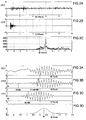
- FIG. 1 shows a course of a received signal that was recorded under real measuring conditions.
- the time in the unit 10 ⁇ s is plotted on the abscissa of the time diagram, and the voltage in the unit Volt is plotted on the ordinate, which was tapped on a piezo disk of an ultrasonic flow meter.
- a comparator whose threshold value is set so that it would switch to the undisturbed received signal according to FIG Switch half-wave, since their amplitude already exceeds the amplitude of the following half-wave. A selection of the wrong half-wave would inevitably lead to the selection of the wrong zero crossing and thus to a measurement error that is an entire wavelength.
- FIG. 2A shows the course of a disturbed received signal, which was sampled, digitized and stored at a sampling frequency of 1 MHz. Since the useful signal, a wave group rising and falling over several vibrations, is a band-limited signal, it is sufficient to select the sampling rate greater than twice the bandwidth of the useful signal. As a result, the entire area of the received signal relevant for the measurement can be evaluated with a comparatively small memory depth. For the rough sampling, a memory for 1000 samples is sufficient to cover a period of 1 ms. This period of time is sufficient for most applications of an ultrasonic flow measurement. In the course of the received signal shown, the wave group of the useful signal is hardly recognizable.
- FIG. 2B shows a reference signal recorded for the case of an undisturbed transmission with the same sampling frequency as in FIG. 2A. With this reference signal, the wave group again emerges clearly.
- a cross-correlation function according to FIG. 2C was obtained by correlating the received signal according to FIG. 2A with the stored reference signal according to FIG. 2B.
- the temporal position of the maximum of the correlation function is a measure of the temporal shift between the known reference signal and the useful signal that is contained in the disturbed received signal.
- the temporal position of the useful signal can thus be calculated with a resolution determined by the sampling rate, for example by evaluating the maximum of the envelope of the correlation function.
- This step of a rough sampling of the received signal in a larger measurement window can be omitted if the approximate temporal position of the useful signal is sufficiently known, for example when the transmission medium has an approximately known speed of sound, or if the position is related to others can be easily determined.
- a coded transmission signal could also serve as a reference signal.
- a smaller measurement window is generated, which is controlled in such a way that the scanning and digitization of the received signal is started immediately before the wave group arrives.
- a now high-resolution scan is carried out at a scan rate that is substantially greater than the carrier frequency of the useful signal and is at least more than four times, preferably more than ten times.
- FIG. 3A shows a disturbed received signal in a measurement window that is shorter in time
- FIG. 3B shows the received signal after filtering with a bandpass filter
- FIG. 3C shows a reference signal which corresponds to an undisturbed received signal
- FIG. 3D shows a correlation function of the filtered received signal according to FIG. 3B and the Reference signal according to Figure 3C.
- the time unit on the abscissa is 10 ⁇ s in each case, the unit on the ordinate is 1 V.
- a signal zero crossing 1 specified for the transit time measurement is shifted by a known time tN compared to an initial time t0 of the measurement window in FIG. 3C.
- 3D related to the value zero, corresponds to a time shift td between the known reference signal according to FIG. 3C and the filtered reception signal according to FIG. 3B within the measurement window.
- the transit time of the received signal can be calculated with a resolution determined by the sampling rate.
- the correlation can also take place with a coded transmission signal, the coding in the simplest case there is a burst-shaped transmission pulse sequence.
- the correlation between the successive received signals can be calculated from measurements upstream and downstream. The temporal position of the maximum of the envelope of the correlation function is then a direct measure of the time difference between the two signals. This method is particularly advantageous when the shape of the received signals deviates greatly from a reference signal obtained in the case of undisturbed transmission because of changed transmission conditions. In general, the match between the upstream and downstream received signals is better and the maximum of the correlation function is more evident.
- the time shift between the received and reference signals can be determined with a resolution that is significantly finer than the period of the oscillations of a wave group.
- a clear determination of the order of the zero crossings of the received signal i. H. a clear numbering within a wave group.
- a predetermined signal zero crossing, in FIG. 3B the signal zero crossing 2, which corresponds to a signal zero crossing 1 in FIG. 3C, which is particularly suitable for the transit time measurement, can thus be reliably selected or detected.
- the measurement window length and thus the memory requirement for storing the samples can be selected to be very small. Accordingly, correspondingly smaller amounts of data have to be processed, so that the processing speed of the runtime measurement increases.
- a storage of 1000 samples of the received signal is sufficient.
- FIG. 4 shows an excerpt from the filtered received signal according to FIG. 3B, which is extended over time.
- the time unit plotted on the abscissa is 1 ⁇ s.
- the individual samples are identified by crosses on the interpolated signal curve.
- the exact temporal position of the zero crossing 2 of the filtered received signal selected in the previous step is determined by an interpolation calculation, which uses several samples immediately before and after the selected zero crossing 2 as input variables, and by calculating the intersection of the interpolating function with the reference potential.
- Which interpolation method is used depends essentially on the performance of the computing unit used for the interpolation. Examples include linear, parabolic or trigonometric interpolation and parameter calculation using the least squares method.
- the zero crossing of predetermined polarity closest to point 2 is selected and the intersection 3 of the interpolating function with the reference potential is calculated.
- the interpolation and the calculation of the point of intersection with the reference potential can achieve a resolution of 10 to 100 ps, which gives very good results for the flow measurement.
- the received signal can be filtered with a narrow-band filter with a high slope before determining the position of the selected zero crossing.
Landscapes
- Physics & Mathematics (AREA)
- Engineering & Computer Science (AREA)
- General Physics & Mathematics (AREA)
- Radar, Positioning & Navigation (AREA)
- Remote Sensing (AREA)
- Computer Networks & Wireless Communication (AREA)
- Electromagnetism (AREA)
- Fluid Mechanics (AREA)
- Acoustics & Sound (AREA)
- Length Measuring Devices Characterised By Use Of Acoustic Means (AREA)
- Measurement Of Velocity Or Position Using Acoustic Or Ultrasonic Waves (AREA)
- Measuring Volume Flow (AREA)
Applications Claiming Priority (2)
| Application Number | Priority Date | Filing Date | Title |
|---|---|---|---|
| DE19611233 | 1996-03-21 | ||
| DE19611233A DE19611233A1 (de) | 1996-03-21 | 1996-03-21 | Verfahren zur Laufzeitmessung eines elektrischen, elektromagnetischen oder akustischen Signals |
Publications (3)
| Publication Number | Publication Date |
|---|---|
| EP0797105A2 true EP0797105A2 (fr) | 1997-09-24 |
| EP0797105A3 EP0797105A3 (fr) | 1999-09-22 |
| EP0797105B1 EP0797105B1 (fr) | 2004-08-11 |
Family
ID=7789025
Family Applications (1)
| Application Number | Title | Priority Date | Filing Date |
|---|---|---|---|
| EP97104518A Expired - Lifetime EP0797105B1 (fr) | 1996-03-21 | 1997-03-17 | Procédé pour la mesure du temp de trajet d'un signal électrique, électromagnétique, ou acoustique |
Country Status (2)
| Country | Link |
|---|---|
| EP (1) | EP0797105B1 (fr) |
| DE (2) | DE19611233A1 (fr) |
Cited By (23)
| Publication number | Priority date | Publication date | Assignee | Title |
|---|---|---|---|---|
| WO2000028348A1 (fr) * | 1998-11-10 | 2000-05-18 | Electronics For Imaging, Inc. | Systeme de positionnement d'un stylet emetteur |
| EP1043602A1 (fr) * | 1999-04-06 | 2000-10-11 | Leica Geosystems AG | Méthode de détection de la distance d'au moins une cible |
| EP1043603A1 (fr) * | 1999-04-06 | 2000-10-11 | Leica Geosystems AG | Méthode de détection de la distance d'au moins une cible |
| WO2000073804A1 (fr) * | 1999-05-27 | 2000-12-07 | The University Of Sydney | Debitmetres acoustiques |
| FR2803383A1 (fr) * | 1999-12-29 | 2001-07-06 | Schlumberger Ind Sa | Procede et dispositif de detection d'un dysfonctionnement pour un debitmetre a ultrasons |
| DE10140346A1 (de) * | 2001-08-17 | 2003-03-06 | Bosch Gmbh Robert | Verfahren zur Entfernungsmessung |
| DE10142538A1 (de) * | 2001-08-30 | 2004-02-12 | Advanced Acoustix Gmbh I.Ins. | Verfahren zur Laufzeitmessung mittels Kreuzkorrelationsfunktion und Kurvenanpassung |
| EP1498700A2 (fr) | 2003-07-16 | 2005-01-19 | AVL List GmbH | Capteur ultrasonique de débit de gaz et dispositif pour mesurer des écoulements de gaz d'échappement de moteurs à combustion interne et procédé pour déterminer le débit de gaz |
| WO2005083626A3 (fr) * | 2003-10-14 | 2005-12-29 | Lord Corp | Procede magnetostrictif de traitement par ondelettes permettant de mesure la duree de propagation de l'impulsion |
| WO2006105761A2 (fr) * | 2005-04-04 | 2006-10-12 | Viasys Healthcare Gmbh | Procede pour determiner la position temporelle d'un paquet de d'ondes et appareil de mesure de flux |
| WO2006128913A1 (fr) * | 2005-06-03 | 2006-12-07 | Siemens Aktiengesellschaft | Procede et dispositif de mesure acoustique de la densite specifique d'un milieu gazeux ou liquide |
| EP2315053A3 (fr) * | 2009-10-20 | 2011-12-21 | Riegl Laser Measurement Systems Gmbh | Dispositifs et procédé de mesure des moments de réception d'impulsions |
| WO2012159703A1 (fr) * | 2011-05-21 | 2012-11-29 | Volkswagen Aktiengesellschaft | Dispositif de détection de l'environnement placé dans un véhicule automobile et procédé de détection de l'environnement utilisant une corrélation |
| WO2013124156A3 (fr) * | 2012-02-23 | 2014-01-23 | Avl List Gmbh | Procédé d'identification des caractéristiques de transmission d'un système, ainsi que caractéristiques de temps de propagation d'ultrasons servant à la détermination de la vitesse de propagation dans un milieu |
| WO2016001638A1 (fr) * | 2014-07-01 | 2016-01-07 | Pcme Limited | Procédé de mesure de temps de vol d'une impulsion ultrasonore |
| CN107131918A (zh) * | 2017-07-02 | 2017-09-05 | 中国计量大学 | 一种低功耗超声波流量计回波信号处理方法及电路 |
| FR3050828A1 (fr) * | 2016-04-28 | 2017-11-03 | Snecma | Procede de determination d'une vitesse d'ecoulement d'un fluide s'ecoulant dans un troncon de conduite et dispositif associe |
| EP3301410A1 (fr) * | 2016-09-29 | 2018-04-04 | Sick AG | Localisation d'un événement au niveau du signal de capteur |
| FR3068126A1 (fr) * | 2017-06-27 | 2018-12-28 | Sagemcom Energy & Telecom Sas | Procede de mesure d'une vitesse d'un fluide |
| CN111323101A (zh) * | 2020-03-24 | 2020-06-23 | 成都千嘉科技有限公司 | 超声波表自适应的自动标定方法 |
| CN113124948A (zh) * | 2021-05-20 | 2021-07-16 | 中国计量大学 | 一种基于fpga与互相关法的高精度时差测量方法 |
| EP3751238A4 (fr) * | 2019-03-15 | 2021-09-15 | Shenzhen Goodix Technology Co., Ltd. | Circuit de correction et circuit de traitement de signal associé, et puce |
| US11543269B2 (en) | 2020-01-27 | 2023-01-03 | Temposonics GmbH & Co. KG | Target detection in magnetostrictive sensors using a target frequency range |
Families Citing this family (10)
| Publication number | Priority date | Publication date | Assignee | Title |
|---|---|---|---|---|
| DE19804958A1 (de) * | 1998-02-07 | 1999-08-12 | Itt Mfg Enterprises Inc | Auswertekonzept für Abstandsmeßverfahren |
| DE10126858A1 (de) * | 2001-06-01 | 2002-12-19 | Siemens Ag | Verfahren zur Bestimmung der Laufzeit in einem Übertragungssystem und zugehörige Komponenten |
| US7925392B2 (en) | 2002-04-23 | 2011-04-12 | Lord Corporation | Aircraft vehicular propulsion system monitoring device and method |
| DK174756B1 (da) * | 2002-06-30 | 2003-10-20 | Siemens Flow Instr As | Fremgangsmåde til måling af flow ved hjælp af en ultralydsflowmåler |
| DE10353598B3 (de) * | 2003-11-12 | 2005-04-21 | Institut für Bioprozess- und Analysenmesstechnik e.V. | Vorrichtung und Verfahren zur Bestimmung einer Stoffkonzentration in einer Probenflüssigkeit |
| JP4283170B2 (ja) * | 2003-12-17 | 2009-06-24 | 株式会社デンソー | 物体検出装置 |
| DE102004027958B4 (de) * | 2004-06-08 | 2007-07-12 | M & Fc Holding Llc | Verfahren und Vorrichtung zum Messen der Strömungsgeschwindigkeit von Fluiden |
| AU2009240769B2 (en) * | 2008-04-22 | 2013-03-21 | Riegl Laser Measurement Systems Gmbh | Apparatus and method for measurement of the reception time of a pulse |
| DE102012212901A1 (de) * | 2012-07-24 | 2014-01-30 | Continental Automotive Gmbh | Verfahren und Vorrichtung zum Betreiben einer akustischen Messvorrichtung |
| CN110646042A (zh) * | 2019-10-16 | 2020-01-03 | 上海交通大学 | 一种用于低功耗超声流量计飞行时间差计算的互相关插值方法 |
Citations (6)
| Publication number | Priority date | Publication date | Assignee | Title |
|---|---|---|---|---|
| EP0109129A1 (fr) * | 1982-11-16 | 1984-05-23 | Philips Patentverwaltung GmbH | Procédé et dispositif de mesure de temps de parcours d'une impulsion ultrasonore |
| DE3726670A1 (de) * | 1987-08-01 | 1989-02-09 | Wanisch Josef Thomas | Abstandsmessgeraet, das auf dem prinzip einer ultraschall-laufzeitmessung beruht |
| WO1994011753A1 (fr) * | 1992-11-12 | 1994-05-26 | Siemens Aktiengesellschaft | Procede d'inspection ultrasonore pour detecter des modeles tridimensionnels |
| US5437506A (en) * | 1991-06-24 | 1995-08-01 | Enel (Ente Nazionale Per L'energia Elettrica) & Cise S.P.A. | System for measuring the transfer time of a sound-wave in a gas and thereby calculating the temperature of the gas |
| WO1995023344A1 (fr) * | 1994-02-28 | 1995-08-31 | Siemens Aktiengesellschaft | Procede permettant de determiner de maniere ultrasonore la position d'un objet par rapport a un arriere-plan |
| WO1995028619A1 (fr) * | 1994-04-19 | 1995-10-26 | Valtion Teknillinen Tutkimuskeskus | Procede de mesure acoustique d'ecoulement et appareil de mesure mettant en oeuvre ce procede |
Family Cites Families (7)
| Publication number | Priority date | Publication date | Assignee | Title |
|---|---|---|---|---|
| DE2607187C3 (de) * | 1976-02-23 | 1986-07-10 | Krautkrämer GmbH, 5000 Köln | Verfahren zur Messung des zeitlichen Impulsabstandes von zwei elektrischen Impulsen |
| DE2923963C2 (de) * | 1979-06-13 | 1986-03-27 | Endress U. Hauser Gmbh U. Co, 7867 Maulburg | Verfahren zur Impulsabstandsmessung und Anordnung zur Durchführung des Verfahrens |
| DE3215097A1 (de) * | 1981-04-27 | 1982-11-18 | International Standard Electric Corp., 10022 New York, N.Y. | Radargeraet, von dem digital kodierte impulse abgestrahlt werden |
| DE3476701D1 (en) * | 1984-10-31 | 1989-03-16 | Honeywell Regelsysteme Gmbh | Method for the emission and reception of a periodical pulse train |
| DE3446837A1 (de) * | 1984-12-21 | 1986-06-26 | Institut Dr. Friedrich Förster Prüfgerätebau GmbH & Co KG, 7410 Reutlingen | Verfahren und vorrichtung zum genauen ermitteln des zeitlichen abstandes zweier elektrischer impulse |
| DK0452531T3 (da) * | 1990-04-20 | 1995-06-19 | Siemens Ag | Fremgangsmåde til løbstidsmåling af et elektrisk signal |
| DE4233677C2 (de) * | 1992-10-07 | 1995-07-13 | Grieshaber Vega Kg | Verfahren zum Korrelationsempfang von vorbekannten periodisch ausgesendeten Impulsen und Vorrichtung zur Durchführung des Verfahrens sowie Verwendung derselben |
-
1996
- 1996-03-21 DE DE19611233A patent/DE19611233A1/de not_active Withdrawn
-
1997
- 1997-03-17 EP EP97104518A patent/EP0797105B1/fr not_active Expired - Lifetime
- 1997-03-17 DE DE59711841T patent/DE59711841D1/de not_active Expired - Lifetime
Patent Citations (6)
| Publication number | Priority date | Publication date | Assignee | Title |
|---|---|---|---|---|
| EP0109129A1 (fr) * | 1982-11-16 | 1984-05-23 | Philips Patentverwaltung GmbH | Procédé et dispositif de mesure de temps de parcours d'une impulsion ultrasonore |
| DE3726670A1 (de) * | 1987-08-01 | 1989-02-09 | Wanisch Josef Thomas | Abstandsmessgeraet, das auf dem prinzip einer ultraschall-laufzeitmessung beruht |
| US5437506A (en) * | 1991-06-24 | 1995-08-01 | Enel (Ente Nazionale Per L'energia Elettrica) & Cise S.P.A. | System for measuring the transfer time of a sound-wave in a gas and thereby calculating the temperature of the gas |
| WO1994011753A1 (fr) * | 1992-11-12 | 1994-05-26 | Siemens Aktiengesellschaft | Procede d'inspection ultrasonore pour detecter des modeles tridimensionnels |
| WO1995023344A1 (fr) * | 1994-02-28 | 1995-08-31 | Siemens Aktiengesellschaft | Procede permettant de determiner de maniere ultrasonore la position d'un objet par rapport a un arriere-plan |
| WO1995028619A1 (fr) * | 1994-04-19 | 1995-10-26 | Valtion Teknillinen Tutkimuskeskus | Procede de mesure acoustique d'ecoulement et appareil de mesure mettant en oeuvre ce procede |
Cited By (43)
| Publication number | Priority date | Publication date | Assignee | Title |
|---|---|---|---|---|
| EP1635186A2 (fr) | 1998-11-10 | 2006-03-15 | Luidia, Inc. | Système de localisation par stylo émetteur |
| US6414673B1 (en) | 1998-11-10 | 2002-07-02 | Tidenet, Inc. | Transmitter pen location system |
| EP1635186A3 (fr) * | 1998-11-10 | 2007-12-05 | Luidia, Inc. | Système de localisation par stylo émetteur |
| WO2000028348A1 (fr) * | 1998-11-10 | 2000-05-18 | Electronics For Imaging, Inc. | Systeme de positionnement d'un stylet emetteur |
| EP1043602A1 (fr) * | 1999-04-06 | 2000-10-11 | Leica Geosystems AG | Méthode de détection de la distance d'au moins une cible |
| EP1043603A1 (fr) * | 1999-04-06 | 2000-10-11 | Leica Geosystems AG | Méthode de détection de la distance d'au moins une cible |
| US6516286B1 (en) | 1999-04-06 | 2003-02-04 | Leica Geosystems Ag | Method for measuring the distance to at least one target |
| WO2000073804A1 (fr) * | 1999-05-27 | 2000-12-07 | The University Of Sydney | Debitmetres acoustiques |
| US6595070B1 (en) | 1999-05-27 | 2003-07-22 | The University Of Sydney | Acoustic flow meters |
| FR2803383A1 (fr) * | 1999-12-29 | 2001-07-06 | Schlumberger Ind Sa | Procede et dispositif de detection d'un dysfonctionnement pour un debitmetre a ultrasons |
| WO2001050095A1 (fr) * | 1999-12-29 | 2001-07-12 | Schlumberger Industries, S.A. | Procede et dispositif de detection d'un dysfonctionnement pour un debitmetre a ultrasons |
| US6766276B1 (en) | 1999-12-29 | 2004-07-20 | Actaris S.A.S. | Method and device for detecting a dysfunction of an ulatrasonic flowmeter |
| DE10140346A1 (de) * | 2001-08-17 | 2003-03-06 | Bosch Gmbh Robert | Verfahren zur Entfernungsmessung |
| DE10140346B4 (de) * | 2001-08-17 | 2012-04-26 | Robert Bosch Gmbh | Verfahren zur Entfernungsmessung |
| US6804168B2 (en) | 2001-08-17 | 2004-10-12 | Robert Bosch Gmbh | Method for measuring distance |
| DE10142538A1 (de) * | 2001-08-30 | 2004-02-12 | Advanced Acoustix Gmbh I.Ins. | Verfahren zur Laufzeitmessung mittels Kreuzkorrelationsfunktion und Kurvenanpassung |
| EP1498700A2 (fr) | 2003-07-16 | 2005-01-19 | AVL List GmbH | Capteur ultrasonique de débit de gaz et dispositif pour mesurer des écoulements de gaz d'échappement de moteurs à combustion interne et procédé pour déterminer le débit de gaz |
| CN1867813B (zh) * | 2003-10-14 | 2011-01-26 | 洛德公司 | 用于测量距离的磁致伸缩传感器 |
| WO2005083626A3 (fr) * | 2003-10-14 | 2005-12-29 | Lord Corp | Procede magnetostrictif de traitement par ondelettes permettant de mesure la duree de propagation de l'impulsion |
| WO2006105761A2 (fr) * | 2005-04-04 | 2006-10-12 | Viasys Healthcare Gmbh | Procede pour determiner la position temporelle d'un paquet de d'ondes et appareil de mesure de flux |
| US8103461B2 (en) | 2005-04-04 | 2012-01-24 | Carefusion Germany 234 Gmbh | Method for determining the temporal position of a wave packet and flow measuring device |
| WO2006105761A3 (fr) * | 2005-04-04 | 2007-05-10 | Viasys Healthcare Gmbh | Procede pour determiner la position temporelle d'un paquet de d'ondes et appareil de mesure de flux |
| WO2006128913A1 (fr) * | 2005-06-03 | 2006-12-07 | Siemens Aktiengesellschaft | Procede et dispositif de mesure acoustique de la densite specifique d'un milieu gazeux ou liquide |
| US7890269B2 (en) | 2005-06-03 | 2011-02-15 | Siemens Aktiengesellschaft | Method and device for acoustic measurement of the specific density of a gaseous or liquid medium |
| EP2315053A3 (fr) * | 2009-10-20 | 2011-12-21 | Riegl Laser Measurement Systems Gmbh | Dispositifs et procédé de mesure des moments de réception d'impulsions |
| US9322916B2 (en) | 2011-05-21 | 2016-04-26 | Volkswagen Ag | Environment monitoring device in a motor vehicle and method for monitoring the environment using a correlation |
| WO2012159703A1 (fr) * | 2011-05-21 | 2012-11-29 | Volkswagen Aktiengesellschaft | Dispositif de détection de l'environnement placé dans un véhicule automobile et procédé de détection de l'environnement utilisant une corrélation |
| CN103703388A (zh) * | 2011-05-21 | 2014-04-02 | 大众汽车有限公司 | 利用相关检测机动车的周围环境的装置和方法 |
| WO2013124156A3 (fr) * | 2012-02-23 | 2014-01-23 | Avl List Gmbh | Procédé d'identification des caractéristiques de transmission d'un système, ainsi que caractéristiques de temps de propagation d'ultrasons servant à la détermination de la vitesse de propagation dans un milieu |
| US20170138773A1 (en) * | 2014-07-01 | 2017-05-18 | Pcme Limited | Method Of Measuring Time Of Flight Of An Ultrasound Pulse |
| WO2016001638A1 (fr) * | 2014-07-01 | 2016-01-07 | Pcme Limited | Procédé de mesure de temps de vol d'une impulsion ultrasonore |
| US10852168B2 (en) | 2014-07-01 | 2020-12-01 | Pcme Limited | Method of measuring time of flight of an ultrasound pulse |
| FR3050828A1 (fr) * | 2016-04-28 | 2017-11-03 | Snecma | Procede de determination d'une vitesse d'ecoulement d'un fluide s'ecoulant dans un troncon de conduite et dispositif associe |
| EP3301410A1 (fr) * | 2016-09-29 | 2018-04-04 | Sick AG | Localisation d'un événement au niveau du signal de capteur |
| FR3068126A1 (fr) * | 2017-06-27 | 2018-12-28 | Sagemcom Energy & Telecom Sas | Procede de mesure d'une vitesse d'un fluide |
| WO2019002145A1 (fr) * | 2017-06-27 | 2019-01-03 | Sagemcom Energy & Telecom Sas | Procede de mesure d'une vitesse d'un fluide |
| US11199429B2 (en) | 2017-06-27 | 2021-12-14 | Sagemcom Energy & Telecom Sas | Method for measuring a speed of a fluid |
| CN107131918A (zh) * | 2017-07-02 | 2017-09-05 | 中国计量大学 | 一种低功耗超声波流量计回波信号处理方法及电路 |
| CN107131918B (zh) * | 2017-07-02 | 2023-09-12 | 中国计量大学 | 一种低功耗超声波流量计回波信号处理方法及电路 |
| EP3751238A4 (fr) * | 2019-03-15 | 2021-09-15 | Shenzhen Goodix Technology Co., Ltd. | Circuit de correction et circuit de traitement de signal associé, et puce |
| US11543269B2 (en) | 2020-01-27 | 2023-01-03 | Temposonics GmbH & Co. KG | Target detection in magnetostrictive sensors using a target frequency range |
| CN111323101A (zh) * | 2020-03-24 | 2020-06-23 | 成都千嘉科技有限公司 | 超声波表自适应的自动标定方法 |
| CN113124948A (zh) * | 2021-05-20 | 2021-07-16 | 中国计量大学 | 一种基于fpga与互相关法的高精度时差测量方法 |
Also Published As
| Publication number | Publication date |
|---|---|
| DE19611233A1 (de) | 1997-09-25 |
| EP0797105B1 (fr) | 2004-08-11 |
| DE59711841D1 (de) | 2004-09-16 |
| EP0797105A3 (fr) | 1999-09-22 |
Similar Documents
| Publication | Publication Date | Title |
|---|---|---|
| EP0797105B1 (fr) | Procédé pour la mesure du temp de trajet d'un signal électrique, électromagnétique, ou acoustique | |
| EP0337293B1 (fr) | Instrument mesureur de niveau | |
| DE2607187C3 (de) | Verfahren zur Messung des zeitlichen Impulsabstandes von zwei elektrischen Impulsen | |
| DE4040190C2 (de) | Verfahren zur Laufzeitmessung von Ultraschall bei der Impuls-Reflexionsmethode | |
| EP0452531B1 (fr) | Dispositif électrique pour mesurer le temps de propagation d'un signal électrique | |
| DE69321141T2 (de) | Rauschreduktion in einem magnetostriktiven positionsgeber durch die ermittlung eines gültigen zeitbereichs für die übertragung von akustischen referenzimpulsen | |
| EP2045625A1 (fr) | Procédé de mesure de distance et dispositif de mesure de distance | |
| DE112009005228T5 (de) | Ultraschall-Detektionsvorrichtung | |
| EP1754025A2 (fr) | Determination de l'instant de reception d'un signal ultrasonore par detection de forme d'impulsion | |
| DE2853170C2 (fr) | ||
| DE3420794C2 (de) | Einrichtung zur Untersuchung von Flüssigkeitseigenschaften | |
| DE3119343C2 (de) | Verfahren zur Ultraschall-Wanddickenmessung | |
| DE102004035715B4 (de) | Schalllaufzeitmessvorrichtung | |
| DE3435989C2 (de) | Verfahren zur Wanddickenmessung von Körpern mittels Ultraschallimpulsen und Vorrichtung zur Durchführung des Verfahrens | |
| EP3517946B1 (fr) | Procédé de détermination d'une valeur corrigée de la vitesse sonique dépendant de la viscosité dans un fluide à analyser | |
| EP0072770B1 (fr) | Procédé et dispositif pour la mesure des différences du temps de transit des impulsions ultrasonores pour la détermination des champs d'écoulement | |
| DE911663C (de) | Verfahren zur Kontrolle, insbesondere zur Entfernungsbestimmung von Objekten nach dem Rueckstrahlprinzip durch impulsweises Aussenden und Wiederempfangen von hochfrequenten Schwingungen | |
| EP1030189A1 (fr) | Dispositif pour détecter la position | |
| DE102010039978A1 (de) | Verfahren und Vorrichtung zur Messung einer Laufzeit eines Pulses | |
| DE10142538A1 (de) | Verfahren zur Laufzeitmessung mittels Kreuzkorrelationsfunktion und Kurvenanpassung | |
| DE102009049069A1 (de) | Verfahren und Vorrichtung zur verbesserten Ultraschall- Laufzeitmessung | |
| DE2813754A1 (de) | Verfahren und vorrichtung zum erkennen der stroemung eines materials durch wellenenergiestrahlung | |
| EP4134699A1 (fr) | Dispositif et procédé de détection d'objets dans une zone de surveillance | |
| DE10353598B3 (de) | Vorrichtung und Verfahren zur Bestimmung einer Stoffkonzentration in einer Probenflüssigkeit | |
| DE10217934A1 (de) | Verfahren und Vorrichtung zur Bestimmung einer Flüssigkeitshöhe mit Hilfe von Ultraschallimpulsen |
Legal Events
| Date | Code | Title | Description |
|---|---|---|---|
| PUAI | Public reference made under article 153(3) epc to a published international application that has entered the european phase |
Free format text: ORIGINAL CODE: 0009012 |
|
| AK | Designated contracting states |
Kind code of ref document: A2 Designated state(s): CH DE DK GB LI NL |
|
| PUAL | Search report despatched |
Free format text: ORIGINAL CODE: 0009013 |
|
| AK | Designated contracting states |
Kind code of ref document: A3 Designated state(s): CH DE DK GB LI NL |
|
| RIC1 | Information provided on ipc code assigned before grant |
Free format text: 6G 01S 15/10 A, 6G 01S 7/527 B, 6G 01F 1/66 B |
|
| 17P | Request for examination filed |
Effective date: 20000317 |
|
| 17Q | First examination report despatched |
Effective date: 20030918 |
|
| GRAP | Despatch of communication of intention to grant a patent |
Free format text: ORIGINAL CODE: EPIDOSNIGR1 |
|
| GRAS | Grant fee paid |
Free format text: ORIGINAL CODE: EPIDOSNIGR3 |
|
| GRAA | (expected) grant |
Free format text: ORIGINAL CODE: 0009210 |
|
| AK | Designated contracting states |
Kind code of ref document: B1 Designated state(s): CH DE DK GB LI NL |
|
| PG25 | Lapsed in a contracting state [announced via postgrant information from national office to epo] |
Ref country code: NL Free format text: LAPSE BECAUSE OF FAILURE TO SUBMIT A TRANSLATION OF THE DESCRIPTION OR TO PAY THE FEE WITHIN THE PRESCRIBED TIME-LIMIT Effective date: 20040811 |
|
| REG | Reference to a national code |
Ref country code: GB Ref legal event code: FG4D Free format text: NOT ENGLISH |
|
| REG | Reference to a national code |
Ref country code: CH Ref legal event code: EP |
|
| REF | Corresponds to: |
Ref document number: 59711841 Country of ref document: DE Date of ref document: 20040916 Kind code of ref document: P |
|
| PG25 | Lapsed in a contracting state [announced via postgrant information from national office to epo] |
Ref country code: DK Free format text: LAPSE BECAUSE OF FAILURE TO SUBMIT A TRANSLATION OF THE DESCRIPTION OR TO PAY THE FEE WITHIN THE PRESCRIBED TIME-LIMIT Effective date: 20041111 |
|
| GBT | Gb: translation of ep patent filed (gb section 77(6)(a)/1977) |
Effective date: 20041230 |
|
| NLV1 | Nl: lapsed or annulled due to failure to fulfill the requirements of art. 29p and 29m of the patents act | ||
| PG25 | Lapsed in a contracting state [announced via postgrant information from national office to epo] |
Ref country code: LI Free format text: LAPSE BECAUSE OF NON-PAYMENT OF DUE FEES Effective date: 20050331 Ref country code: CH Free format text: LAPSE BECAUSE OF NON-PAYMENT OF DUE FEES Effective date: 20050331 |
|
| PLBE | No opposition filed within time limit |
Free format text: ORIGINAL CODE: 0009261 |
|
| STAA | Information on the status of an ep patent application or granted ep patent |
Free format text: STATUS: NO OPPOSITION FILED WITHIN TIME LIMIT |
|
| 26N | No opposition filed |
Effective date: 20050512 |
|
| REG | Reference to a national code |
Ref country code: CH Ref legal event code: PL |
|
| PG25 | Lapsed in a contracting state [announced via postgrant information from national office to epo] |
Ref country code: DE Free format text: LAPSE BECAUSE OF NON-PAYMENT OF DUE FEES Effective date: 20111001 |
|
| PGFP | Annual fee paid to national office [announced via postgrant information from national office to epo] |
Ref country code: GB Payment date: 20120312 Year of fee payment: 16 |
|
| PGFP | Annual fee paid to national office [announced via postgrant information from national office to epo] |
Ref country code: DE Payment date: 20120518 Year of fee payment: 16 |
|
| GBPC | Gb: european patent ceased through non-payment of renewal fee |
Effective date: 20130317 |
|
| REG | Reference to a national code |
Ref country code: DE Ref legal event code: R119 Ref document number: 59711841 Country of ref document: DE Effective date: 20131001 |
|
| PG25 | Lapsed in a contracting state [announced via postgrant information from national office to epo] |
Ref country code: GB Free format text: LAPSE BECAUSE OF NON-PAYMENT OF DUE FEES Effective date: 20130317 |
|
| PG25 | Lapsed in a contracting state [announced via postgrant information from national office to epo] |
Ref country code: DE Free format text: LAPSE BECAUSE OF NON-PAYMENT OF DUE FEES Effective date: 20131001 |