EP0797040A2 - Flexible Rohrverbindung - Google Patents
Flexible Rohrverbindung Download PDFInfo
- Publication number
- EP0797040A2 EP0797040A2 EP96108062A EP96108062A EP0797040A2 EP 0797040 A2 EP0797040 A2 EP 0797040A2 EP 96108062 A EP96108062 A EP 96108062A EP 96108062 A EP96108062 A EP 96108062A EP 0797040 A2 EP0797040 A2 EP 0797040A2
- Authority
- EP
- European Patent Office
- Prior art keywords
- face
- restricting
- cylindrical member
- groove
- peripheral face
- Prior art date
- Legal status (The legal status is an assumption and is not a legal conclusion. Google has not performed a legal analysis and makes no representation as to the accuracy of the status listed.)
- Granted
Links
- 230000002093 peripheral effect Effects 0.000 claims abstract description 121
- 238000003780 insertion Methods 0.000 claims abstract description 14
- 230000037431 insertion Effects 0.000 claims abstract description 14
- 230000000717 retained effect Effects 0.000 claims description 12
- 229910001018 Cast iron Inorganic materials 0.000 claims description 7
- 238000005452 bending Methods 0.000 claims description 6
- XEEYBQQBJWHFJM-UHFFFAOYSA-N Iron Chemical compound [Fe] XEEYBQQBJWHFJM-UHFFFAOYSA-N 0.000 claims 2
- 150000002500 ions Chemical class 0.000 claims 1
- 229910052742 iron Inorganic materials 0.000 claims 1
- 238000010276 construction Methods 0.000 description 19
- 230000005489 elastic deformation Effects 0.000 description 8
- 230000004323 axial length Effects 0.000 description 6
- 229910001220 stainless steel Inorganic materials 0.000 description 5
- 239000010935 stainless steel Substances 0.000 description 5
- 239000012530 fluid Substances 0.000 description 4
- 230000014759 maintenance of location Effects 0.000 description 4
- 239000000463 material Substances 0.000 description 4
- 238000007789 sealing Methods 0.000 description 4
- 239000003566 sealing material Substances 0.000 description 4
- 229920003048 styrene butadiene rubber Polymers 0.000 description 4
- 229920003051 synthetic elastomer Polymers 0.000 description 4
- 239000005061 synthetic rubber Substances 0.000 description 4
- 230000000694 effects Effects 0.000 description 3
- 230000006872 improvement Effects 0.000 description 2
- 238000010008 shearing Methods 0.000 description 2
- 239000008399 tap water Substances 0.000 description 2
- 235000020679 tap water Nutrition 0.000 description 2
- XLYOFNOQVPJJNP-UHFFFAOYSA-N water Substances O XLYOFNOQVPJJNP-UHFFFAOYSA-N 0.000 description 2
- 230000008901 benefit Effects 0.000 description 1
- 230000003247 decreasing effect Effects 0.000 description 1
- 238000000034 method Methods 0.000 description 1
- 230000004048 modification Effects 0.000 description 1
- 238000012986 modification Methods 0.000 description 1
- 230000003449 preventive effect Effects 0.000 description 1
- 230000008569 process Effects 0.000 description 1
- 238000003466 welding Methods 0.000 description 1
Images


Classifications
-
- F—MECHANICAL ENGINEERING; LIGHTING; HEATING; WEAPONS; BLASTING
- F16—ENGINEERING ELEMENTS AND UNITS; GENERAL MEASURES FOR PRODUCING AND MAINTAINING EFFECTIVE FUNCTIONING OF MACHINES OR INSTALLATIONS; THERMAL INSULATION IN GENERAL
- F16L—PIPES; JOINTS OR FITTINGS FOR PIPES; SUPPORTS FOR PIPES, CABLES OR PROTECTIVE TUBING; MEANS FOR THERMAL INSULATION IN GENERAL
- F16L27/00—Adjustable joints; Joints allowing movement
- F16L27/02—Universal joints, i.e. with mechanical connection allowing angular movement or adjustment of the axes of the parts in any direction
- F16L27/026—Universal and axially displaceable joints
-
- F—MECHANICAL ENGINEERING; LIGHTING; HEATING; WEAPONS; BLASTING
- F16—ENGINEERING ELEMENTS AND UNITS; GENERAL MEASURES FOR PRODUCING AND MAINTAINING EFFECTIVE FUNCTIONING OF MACHINES OR INSTALLATIONS; THERMAL INSULATION IN GENERAL
- F16L—PIPES; JOINTS OR FITTINGS FOR PIPES; SUPPORTS FOR PIPES, CABLES OR PROTECTIVE TUBING; MEANS FOR THERMAL INSULATION IN GENERAL
- F16L27/00—Adjustable joints; Joints allowing movement
- F16L27/02—Universal joints, i.e. with mechanical connection allowing angular movement or adjustment of the axes of the parts in any direction
- F16L27/04—Universal joints, i.e. with mechanical connection allowing angular movement or adjustment of the axes of the parts in any direction with partly-spherical engaging surfaces
-
- F—MECHANICAL ENGINEERING; LIGHTING; HEATING; WEAPONS; BLASTING
- F16—ENGINEERING ELEMENTS AND UNITS; GENERAL MEASURES FOR PRODUCING AND MAINTAINING EFFECTIVE FUNCTIONING OF MACHINES OR INSTALLATIONS; THERMAL INSULATION IN GENERAL
- F16L—PIPES; JOINTS OR FITTINGS FOR PIPES; SUPPORTS FOR PIPES, CABLES OR PROTECTIVE TUBING; MEANS FOR THERMAL INSULATION IN GENERAL
- F16L27/00—Adjustable joints; Joints allowing movement
- F16L27/12—Adjustable joints; Joints allowing movement allowing substantial longitudinal adjustment or movement
- F16L27/125—Adjustable joints; Joints allowing movement allowing substantial longitudinal adjustment or movement having longitudinal and rotary movement
Definitions
- the present invention relates to a flexible pipe connector, and more particularly to a pipe connector including a first cylindrical member and a second cylindrical member inserted into the first cylindrical member, the first cylindrical member defining, in an inner peripheral face thereof, an annular restricting groove, the second cylindrical member defining, in an outer peripheral face thereof, an annular attaching groove having a shorter axial length than the annular restricting groove of the first cylindrical member, the attaching groove being detachably attached with a radially deformable retaining member for coming into contact with an axial end face of the restricting groove for restricting range of relative axial movement between the two cylindrical members, the outer peripheral face of the second cylindrical member and the inner peripheral face of the first cylindrical member being provided with a radial opposing distance therebetween determined so as to allow insertion and withdrawal of the retaining member.
- the second cylindrical member is inserted into the first cylindrical member, when a leading end of the second cylindrical member is placed at an axially intermediate portion of the restricting groove defined in the inner peripheral face of the first cylindrical member. Then, through the annular gap formed between the outer peripheral face of the second cylindrical member and the inner peripheral face of the first cylindrical member, the retaining member which is being radially expanded is inserted from the leading end of the second cylindrical member to the attaching groove of the same. In this condition, the radially expanded condition of the retaining member is released to allow this retaining member to be reduced radially to elastically fit the attaching groove.
- the annular gap for insertion/withdrawal of the retaining member is formed between the outer peripheral face of the second cylindrical member and the inner peripheral face of the first cylindrical member. Therefore, an external force in the withdrawing direction generated in association with an earthquake or differential settlement affects both of the two cylindrical members which are un-withdrawably and expandably connected to each other within the movable range determined by the length of the restricting groove.
- the retaining member fitted to the attaching groove of the second cylindrical member is strongly pressed in the axial direction against one end face of the restricting groove located on the side of the entrance opening of the first cylindrical member, when the retaining member is urged to elastically deform or expand radially, so that this retaining member may be inadvertently detached or withdrawn from the attaching groove of the second cylindrical member.
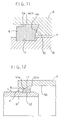
- a conventional flexible pipe connector has a construction shown in Fig. 12.
- a contact face 50a of the restricting groove 50 and a contact face 51a of the retaining member 51 are formed respectively as a tapered face having a decreasing diameter toward the entrance opening (a) of the first cylindrical member A, so that these tapered contact faces 50a, 51a come into contact against each other in the axial direction when such withdrawing-direction external force is applied to the two cylindrical members A, B.
- the tapered contact face 50a of the restricting groove 50 has a minimum diameter which is same as or smaller than a minimum outside diameter of the tapered contact face 51a of the retaining member 51 (see Japanese un-examined utility model gazette No. 4-136392 for example).
- the present invention attends to the above-described state of the art, and its primary object is to provide a flexible pipe connector which may be formed compact in the radial direction and which yet is capable of preventing inadvertent withdrawal of the two cylindrical members more effectively.
- a flexible pipe connector for accomplishing the above-noted object, comprises:
- the portion of the retaining member contacting against the one end face of the restricting groove of the first cylindrical member and the further portion of the retaining member contacting against the attaching groove of the second cylindrical member are radially displaced relative to each other.
- at least those port ion of the mutually contacting respective end faces of the restricting groove and the retaining member are formed as faces extending substantially normal to the cylinder axis or as tapered faces extending radially outward as approaching the entrance opening of the first cylindrical member.
- the retaining member is twisted and pivoted in a direction where a diagonal direction of a cross section of this retaining member is aligned with the cylinder radial direction, with using the portion of the retaining member contacting the end face of the restricting groove of the first cylindrical member and the further portion of the retaining member contacting the attaching groove of the second cylindrical member as reaction points for the pivotal movement.
- the retaining member comes into contact with the radial-expansion restricting portion, whereby the retaining member may be reliably prevented from being withdrawn from the attaching groove.
- the flexible pipe connector since the radial length of the retaining member (consequently, the diagonal length of the cross section of this retaining member) functions effectively for preventing inadvertent withdrawal, the flexible pipe connector, according to the present invention, may be formed compact in the radial direction, yet may achieve superior withdrawal preventive effect, in comparison with the conventional construction described hereinbefore.
- the radial-expansion restricting portion comprises a radial-expansion restricting face formed at an end of an inner peripheral face of the restricting groove in such a manner as to come into contact with or come closer to the outer peripheral face of the retaining member contacting against the end face of the restricting groove.
- the withdrawing external force applied to the two cylindrical members may be received in a distributed state by the large mutually contacting portions of the end face of the retaining member and the one end face of the attaching groove of the second cylindrical member, respectively.
- the radial-expansion restricting portion comprises a radial-expansion restricting face of a restricting member engaged and retained at one end of the inner peripheral face of the restricting groove in such a manner as to come into contact with or come closer to the outer peripheral face of the retaining member contacting against the end face of the restricting groove.
- a conventional flexible pipe connector in which a radial mutual opposing distance between the outer peripheral face of the second cylindrical member and the inner peripheral face of the restricting groove of the first cylindrical member is set so as to allow insertion/withdrawal of the restricting member over the entire axial length of the restricting groove, may be modified to achieve the above-described effect, with such simple and economical modification for causing the restricting member to be engaged and retained at the one end of the inner peripheral face of the restricting groove of this pipe connector.
- the outer peripheral face and the radial-expansion restricting face of the retaining member are formed respectively as a tapered face gradually reduced in the radial direction as approaching the entrance opening of the first cylindrical member.
- the two cylindrical members may move more smoothly relatively to each other within the range defined by the length of the restricting groove, while the radial-expansion restricting face of the radial-expansion restricting portion is brought into contact with the outer peripheral face of the retaining member fitted to the attaching groove of the second cylindrical member when the retaining member comes into contact against the one end face of the restricting groove in association with application of withdrawing external force.
- the restricting member is capable of radially inward bending deformation and this restricting member is engaged and retained, under a radially reduced condition, at the one end of the inner peripheral face of the restricting groove.
- the restricting member may be caused to be engaged and retained at the one end of the inner peripheral face of the restricting groove, by utilizing the radially inward elastic resilience of this restricting member per se. Accordingly, this construction provides the advantage of facilitating the process needed for causing the restricting member to be engaged and retained at a predetermined position within the restricting groove.
- an intermediate portion of the restricting groove of the first cylindrical member relative to the cylinder axis is formed as a radially bulging portion.
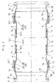
- Figs. 1 through 3 show a flexible pipe connector 1 for use in transport of fluid (e.g. tap water).
- fluid e.g. tap water
- a second connector pipe 2 made of cast iron Into each of opposed ends of a first connector pipe made of cast iron as a first cylindrical member A, there is slidably inserted a second connector pipe 2 made of cast iron and forming, on the side of one end thereof, a partially spherical outer peripheral face 2a along a direction of cylinder axis X (cylinder axis direction). Further, on each of the outer peripheral face 2a of a spherical pipe portion 2A of the second connector pipe 2, there is slidably fitted a partially spherical inner peripheral face 3a formed at one end of a third connector pipe 3 made of cast iron and provided as a third cylindrical member C.
- An annular attaching groove 5 is defined in the outer peripheral face of a straight pipe portion 2B of the second connector pipe 2.
- This attaching groove 5 has an axial length along the cylinder axis X shorter than an axial length of an annular restricting groove 4 defined at an intermediate portion in the cylinder axis direction X in the inner peripheral face of the first connector pipe 1.
- a retaining member 6 which is made of stainless steel and which is radially flexible. This restricting member 6 is brought into face contact with an end face 4a of the restricting groove 4 in the cylinder axis direction X, so as to restrict range of relative movement between the first connector pipe 1 and the second connector pipe 2 in the direction of cylinder axis X.
- a mutually opposing radial distance between the outer peripheral face of the straight pipe portion 2B of the second connector pipe 2 and the inner peripheral face of the first connector pipe 1 is designed so as to allow insertion and withdrawal of the retaining member 6.
- an annular space for allowing insertion/withdrawal of the retaining member 6 is formed between the opposing faces, i.e. between the outer peripheral face of the straight pipe portion 2B of the second connector pipe 2 and the inner peripheral face 4b of the restricting groove 4.
- a radial-expansion restricting portion 7 When an external force in the withdrawing direction generated in association with an earthquake or differential settlement is applied to the flexible pipe connector to cause the respective retaining member 6 fitted to the attaching groove 5 of the second connector pipe 2 to come into contact, along the cylinder axis X, against the end face 4a of the restricting groove 4 located on the side of the entrance opening (a) of the first connector pipe 1 (i.e. the side for allowing insertion of the second connector pipe 2), the radial-expansion restricting portion 7 functions to prevent, through contact, withdrawal of this restricting member 6 from the attaching groove 5 in the direction of cylinder axis X. Further, as shown in Fig.
- the outer peripheral face of the straight pipe portion 2B of the second connector pipe 2 includes, as an integral projection thereof, an annular stopper portion 8.
- This annular stopper portion 8 comes into face contact with the end face 1a of the first connector pipe 1 in the direction of cylinder axis X when the first connector pipe 1 and the second connector pipe 2 are moved relative to each other beyond a predetermined movement range.
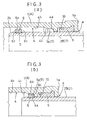
- Each of the radial-expansion restricting portion 7 is constructed from a radial-expansion restricting face 7a formed adjacent one end of the inner peripheral face 4b of the restricting groove 4 in the vicinity of the outer peripheral face 6a of the retaining member 6 when contacting the end face 4a of the restricting groove 4.
- the outer peripheral face 6a of the retaining member 6 and the radial-expansion restricting face 7a are respectively formed parallel with or substantially parallel with the cylinder axis X.
- each of the end face 6c of the retaining member 6 in the direction of cylinder axis X and the opposed end faces 4a of the restricting groove 4 in the direction of cylinder axis X is formed as a flat face extending normal or substantially normal to the cylinder axis X.
- a border portion 4c extending continuously from the radial-expansion restricting face 7a is formed as a tapered face.
- An annular seal retaining groove 10 is formed adjacent each of opposed ends, in the direction of the cylinder axis X, in the inner peripheral face of the first connector pipe 1.
- This seal retaining groove 10 retains a first elastic sealing material 9 made of synthetic rubber material (e.g. styrene-butadiene rubber) for sealing between the inner peripheral face of the first connector pipe 1 and the outer peripheral face of the straight pipe portion 2B of the second connector pipe 2.
- the inner peripheral face 3a of the spherical pipe portion 3A of the third connector pipe 3 defines an annular seal retaining groove 12.
- This seal retaining groove 12 retains a second elastic sealing material 11 made of synthetic rubber material (e.g.
- a connector flange 3C is formed integrally with the end of the straight pipe portion 3B of the third connector pipe 3.
- This connector flange 3C includes a plurality of connecting through holes 3b coaxially arranged for fixedly connecting a certain external piping device P such as a fluid transport pipe (e.g. water pipe) or a sluice valve by means of bolts and nuts.
- the sliding guide member 13 On the inner peripheral face, in the vicinity of the entrance opening, of the spherical pipe portion 3A of the third connector pipe 3, there are attached a sliding guide member 13 made of cast iron and a stopper member 14 made of stainless steel.
- the sliding guide member 13 includes a partially spherical sliding face 13a for coming into sliding contact with the outer peripheral face 2a of the spherical pipe portion 2A of the second connector pipe 2.
- the stopper member 14 is constructed as a C-shaped member radially flexible for preventing inadvertent withdrawal of the sliding guide member 13.
- the straight pipe portion 2B of the second connector pipe 2 defines, at the leading end thereof, a tapered face 2b adapted for guiding the retaining member 6 while radially expanding it.
- the retaining member 6 is constructed as a C-shaped ring member having one peripheral portion thereof cutaway, and at opposed free ends of this C-shaped member, there are formed radial-expansion operating holes 6b for allowing elastic radial expansion of the retaining member 6 by some appropriate tool.
- the portion of the retaining member 6 contacting against the one end face 4a of the restricting groove 4 of the first connector pipe 1 and the further portion of the retaining member 6 contacting against the end face of the attaching groove 5 of the second connector pipe 2 are radially displaced relative to each other.
- the respective end faces 4a, 6c of the restricting groove 4 and the retaining member 6 are formed as flat faces extending substantially normal to the cylinder axis X.
- the retaining member 6 is twisted and pivoted in a direction where a diagonal direction of a cross section of this retaining member 6 is aligned with the cylinder radial direction, with using the portion of the retaining member 6 contacting the end face 4a of the restricting groove 4 of the first connector pipe 1 and the further portion of the retaining member 6 contacting the end face of the attaching groove 5 of the second connector pipe 2 as reaction points for the pivotal movement.
- the retaining member 6 comes into contact with the radial-expansion restricting face 7a, whereby the retaining member 6 may be reliably prevented from being withdrawn from the attaching groove 5.
- the second connector pipe 2 and the third connector pipe 3 may be flexed relative to each other, thereby to restrict damage to the flexible pipe connector.
- the stopper portion 8 formed as a projection from the outer peripheral face of the straight pipe portion 2B of the second connector pipe 2 is designed so as to remain outside the flexion pivoting range of the opened end face of the spherical pipe portion 3A of the third connector pipe 3.
- the stopper portion 8 prevents, through contact, the end face 1a of the first connector pipe 1 slidably radially retracting relative to the straight pipe portion 2B of the second connector pipe 2 from coming into the flexion pivotal range of the opened end of the spherical pipe portion 3A of the third connector pipe 3, so that the second connector pipe 2 and the third connector pipe 3 may always flex relative to each other to the maximum angle in a reliable manner.
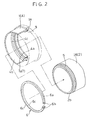
- Figs. 4 and 5 show a flexible pipe connector for use in transport of fluid (e.g. tap water).
- fluid e.g. tap water.
- Each of opposed ends of a second connector pipe 16 in the form of a straight pipe made of cast iron as a second cylindrical member B is slidably inserted, in the direction of cylinder axis X, into a first spherical ring member 15 made of cast iron as a first cylindrical member A having a partially spherical configuration.
- a partially spherical inner peripheral face 17a formed at one end of a third connector pipe 3.
- An annular attaching groove 5 is defined at an end in the direction of cylinder axis X in the outer peripheral face of the second connector pipe 16.
- This attaching groove 5 has an axial length along the cylinder axis X shorter than an axial length of an annular restricting groove 4 defined at an intermediate portion in the cylinder axis direction X of the inner peripheral face of the spherical ring member 15.
- a retaining member 6 which is made of stainless steel and which is radially flexible.
- This retaining member 6 is brought into face contact with an end face 4a, 4d of the restricting groove 4 in the cylinder axis direction X, so as to restrict range of relative movement between the spherical ring member 15 and the second connector pipe 16 in the direction of cylinder axis X.
- a mutually opposing radial distance between the outer peripheral face of the second connector pipe 16 and the inner peripheral face 4b of the restricting groove 4 is designed so as to allow insertion and withdrawal of the retaining member 6.
- an annular space for allowing insertion/withdrawal of the retaining member 6 is formed between the opposing faces, i.e. between the outer peripheral face of the second connector pipe 2 and the inner peripheral face 4b of the restricting groove 4.
- a radial-expansion restricting portion 7 When an external force in the withdrawing direction generated in association with an earthquake or differential settlement is applied to the flexible pipe connector to cause the retaining member 6 fitted to the attaching groove 5 of the second connector pipe 16 to come into contact, along the cylinder axis X, against the end face 4a of the restricting groove 4 located on the side of the entrance opening (a) of the spherical ring member 15 (i.e. the side for allowing insertion of the second connector pipe 16), the radial-expansion restricting portion 7 functions to prevent, through contact, withdrawal of this restricting member 6 from the attaching groove 5 in the direction of cylinder axis X.
- Each of the radial-expansion restricting portion 7 is constructed from a radial-expansion restricting face 7a formed adjacent one end of the inner peripheral face 4b of the restricting groove 4 in the vicinity of the outer peripheral face 6a of the retaining member 6 when contacting the end face 4a of the restricting groove 4.
- the outer peripheral face 6a of the retaining member 6 and the radial-expansion restricting face 7a are respectively formed parallel with or substantially parallel with the cylinder axis X.
- each of the end face 6c of the retaining member 6 in the direction of cylinder axis X and the opposed end faces 4a, 4d of the restricting groove 4 in the direction of cylinder axis X is formed as a flat face extending normal or substantially normal to the cylinder axis X.
- a border portion 4c extending continuously from the each radial-expansion restricting face 7a is formed as a tapered face.
- An annular seal retaining groove 19 is formed adjacent each of opposed ends, in the direction of the cylinder axis X, in the inner peripheral face of the spherical ring member 15.
- This zeal retaining groove 19 retains a third elastic sealing material 18 made of synthetic rubber material (e.g. styrene-butadiene rubber) for sealing between the inner peripheral face of the spherical ring member and the outer peripheral face of the second connector pipe 16.
- the inner peripheral face 17a of the spherical pipe portion 17A of the third connector pipe 17 defines an annular seal retaining groove 21.
- This seal retaining groove 21 retains a fourth elastic sealing material 20 made of synthetic rubber material (e.g.
- a connector flange 17C is formed integrally with an end of the straight pipe portion 17B of the third connector pipe 17.
- This connector flange 17C includes a plurality of connecting through holes 17b coaxially arranged for fixedly connecting a certain external piping device P such as a fluid transport pipe (e.g. water pipe) or a sluice valve by means of bolts and nuts.
- the outer peripheral face of the second connector pipe 16 includes, adjacent the leading end thereof, a tapered face 16a adapted for guiding the retaining member 6 while radially expanding it.
- the retaining member 6 is constructed as a C-shaped ring member having one peripheral portion thereof cutaway, and at opposed free ends of this C-shaped there are formed radial-expansion operating holes for allowing elastic radial expansion of the retaining member 6 by some appropriate tool.
- the portion of the retaining member 6 contacting against the one end face 4a of the restricting groove 4 of the spherical ring member 15 and the further portion of the retaining member 6 contacting against the end face of the attaching groove 5 of the second connector pipe 16 are radially displaced relative to each other.
- the respective end faces 4a, 6c of the restricting groove 4 and the retaining member 6 are formed as flat faces extending substantially normal to the cylinder axis X.
- the retaining member 6 is twisted and pivoted in a direction where a diagonal direction of a cross section of this retaining member 6 is aligned with the cylinder radial direction, with using the portion of the retaining member 6 contacting the end face 4a of the restricting groove 4 of the spherical ring member 15 and the further portion of the retaining member 6 contacting the end face of the attaching groove 5 of the second connector pipe 16 as reaction points for the pivotal movement.
- the retaining member 6 comes into contact with the radial-expansion restricting face 7a, whereby the retaining member 6 may be reliably prevented from being withdrawn from the attaching groove 5.
- each of the outer peripheral face 6a of the retaining member 6 and the radial-expansion restricting face 7a is formed as a flat face extending parallel with or substantially parallel with the cylinder axis X.
- each of at least a portion of the outer peripheral face 6a of the retaining member 6 and the radial-expansion restricting face 7a may be formed as a tapered face gradually reduced in diameter toward the entrance opening (a) of the first connector pipe 1 (i.e. the side for allowing insertion of the second connector pipe 2) to come into contact with or come close to the outer peripheral face 6a of the retaining member 6 when contacting the end face 4a of the restricting groove 4.
- each of at least a portion of the outer peripheral face 6a of the retaining member 6 and the radial-expansion restricting face 7a described in the second embodiment may be formed as a tapered face gradually reduced in diameter toward the entrance opening of the spherical ring member 15 (i.e. the side for allowing insertion of the second connector pipe 16) to come into contact with or come close to the outer peripheral face 6a of the retaining member 6 contacting the end face 4a of the restricting groove 4.
- the radial-expansion restricting portion 7 is constructed from the radial-expansion restricting face 7a formed at one end of the inner peripheral face 4b of the restricting groove 4 in the vicinity of the outer peripheral face 6a of the retaining member 6 contacting the one end face 4a of the restricting groove 4.
- the radial-expansion restricting portion 7 may be constructed from a radial-expansion restricting face 7a of the inner peripheral face of the restricting member 7A formed of stainless steel engaged and retained at one end of the inner peripheral face 4b of the restricting groove 4 for coming into contact with or coming closer to the outer peripheral face 6a of the retaining member 6 when contacting the one end face 4a of the restricting groove 4.
- the restricting member 7A is comprised of an annular ring member having one peripheral portion thereof cutaway and this member 7A is capable of elastic deformation (bending deformation) radially inwards (radially reducing direction) and is engaged and retained, under the radially reduced condition, at the one end of the inner peripheral face 4b of the restricting groove 4.
- a radial-reduction operating hole 7b for allowing this restricting member 7A to effect the radially reducing elastic deformation (bending deformation) by means of some appropriate tool.
- the radial-expansion restricting face 7a described in the second embodiment may be constructed from a radial-expansion restricting face 7a of the inner peripheral face of the restricting member 7A formed of stainless steel engaged and retained at one end of the inner peripheral face 4b of the restricting groove 4 for coming into contact with or coming closer to the outer peripheral face 6a of the retaining member 6 when contacting the one end face 4a of the restricting groove 4.
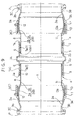
- Fig. 9 shows a construction in which a portion of the first connector pipe 1 described in the first embodiment is modified for improvement. Namely, in this first connector pipe 1, a portion 1A thereof located at an intermediate position of the restricting groove 4 in the direction of cylinder axis X is formed as a radially bulging portion.
- Figs. 10(a) and (b) show improvement of the flexible pipe connector described in the second embodiment.
- the radial-expansion restricting portion 7 is provided. This portion 7 prevents the restricting member 6 from being withdrawn from the attaching groove 5 when an external force in the withdrawing direction is applied to the flexible pipe connector due to an earthquake or differential settlement to cause the restricting member 6 fitted to the attaching groove 5 of the second connector pipe 16 to come into contact, along the direction of cylinder axis X, with the one end face 4a of the restricting groove 4 located on the side of the entrance opening (a) of the spherical ring member 15.
- another radial-expansion restricting portion 7 is provided to the other end face 4d of the restricting groove 4 of the spherical ring member 15.
- This restricting portion 7 prevents the retaining member 6 from being withdrawn from the attaching groove 5 when an external force in the withdrawing direction is applied to the flexible pipe connector due to an earthquake or differential settlement to cause the restricting member 6 fitted to the attaching groove 5 of the second connector pipe 16 to come into face contact, along the direction of cylinder axis X, with the other end face 4d of the restricting groove 4 of the spherical ring member 15.
- the radial-expansion restricting portions 7 constructed respectively from the radial-expansion restricting faces 7a formed at the opposed ends of the inner peripheral face 4b of the restricting groove 4 in the vicinity of the outer peripheral face 6a of the retaining member 6 contacting the end faces 4a, 4d of the restricting groove 4.
- each of the end face 4a of the restricting groove 4 and the end face 6c of the retaining member 6 is formed as a face extending normal or substantially normal to the cylinder axis X.
- at least a portion of the contacting faces, i.e. of the end face 4a of the restricting groove 4 of the first cylindrical member A (i.e. the first connector pipe 1 or the spherical ring member 15) and the end face 6c of the retaining member 6 fitted to the attaching groove 5 of the second cylindrical member B (i.e. the second connector pipe 2 or 16) may be formed as a tapered face extending radially outwards as approaching the entrance opening (a) of the first cylindrical member A.
Landscapes
- Engineering & Computer Science (AREA)
- General Engineering & Computer Science (AREA)
- Mechanical Engineering (AREA)
- Quick-Acting Or Multi-Walled Pipe Joints (AREA)
- Joints Allowing Movement (AREA)
- Joints With Sleeves (AREA)
- Mutual Connection Of Rods And Tubes (AREA)
Applications Claiming Priority (3)
| Application Number | Priority Date | Filing Date | Title |
|---|---|---|---|
| JP6399296 | 1996-03-21 | ||
| JP63992/96 | 1996-03-21 | ||
| JP06399296A JP3415985B2 (ja) | 1996-03-21 | 1996-03-21 | 伸縮管継手 |
Publications (3)
| Publication Number | Publication Date |
|---|---|
| EP0797040A2 true EP0797040A2 (de) | 1997-09-24 |
| EP0797040A3 EP0797040A3 (de) | 1999-03-24 |
| EP0797040B1 EP0797040B1 (de) | 2002-07-31 |
Family
ID=13245290
Family Applications (1)
| Application Number | Title | Priority Date | Filing Date |
|---|---|---|---|
| EP96108062A Expired - Lifetime EP0797040B1 (de) | 1996-03-21 | 1996-05-21 | Flexible Rohrverbindung |
Country Status (7)
| Country | Link |
|---|---|
| US (2) | US5897146A (de) |
| EP (1) | EP0797040B1 (de) |
| JP (1) | JP3415985B2 (de) |
| CA (1) | CA2176855C (de) |
| DE (1) | DE69622687T2 (de) |
| SG (1) | SG45475A1 (de) |
| TW (1) | TW384360B (de) |
Cited By (6)
| Publication number | Priority date | Publication date | Assignee | Title |
|---|---|---|---|---|
| DE29813385U1 (de) * | 1998-07-28 | 1999-12-09 | Seppelfricke Armaturen GmbH & Co., 45881 Gelsenkirchen | Anschlußarmatur für einen Wasserzähler o.dgl. |
| EP1201983A3 (de) * | 2000-09-27 | 2002-05-15 | General Electric Company | Methode und Vorrichtung zum Zusammensetzen von Verbindungen zur Flüssigkeitsübertragung |
| EP1079163A3 (de) * | 1999-08-26 | 2002-12-18 | Waterworks Technology Development Organization Co., Ltd. | Flexible Dehnverbindung für Rohrleitungen und Verfahren zu ihrem Zusammenbau |
| WO2003029716A1 (en) * | 2001-10-04 | 2003-04-10 | Oystertec Plc | Connections |
| WO2007020504A3 (en) * | 2005-08-15 | 2007-04-19 | Eaton Corp | Fluid line assembly |
| CN104728546A (zh) * | 2015-03-13 | 2015-06-24 | 中益诚达建设集团有限公司 | 一种抗震管道软连接 |
Families Citing this family (44)
| Publication number | Priority date | Publication date | Assignee | Title |
|---|---|---|---|---|
| JPH1061853A (ja) * | 1996-06-11 | 1998-03-06 | Nippon Buikutoritsuku Kk | 伸縮可撓継手 |
| US6119825A (en) * | 1998-08-21 | 2000-09-19 | Reliance Electric Technologies, Llc | Motor brake having improved torque adjustment mechanism |
| US6131960A (en) * | 1998-10-16 | 2000-10-17 | Mchughs; Larry | Packing sealed expansion joint |
| US6449942B1 (en) * | 1999-06-24 | 2002-09-17 | Lockheed Martin Corporation | Slip joint duct system |
| JP4409668B2 (ja) * | 1999-07-27 | 2010-02-03 | 株式会社水道技術開発機構 | 伸縮管継手の組立方法 |
| DE10015911B4 (de) * | 2000-03-30 | 2006-06-29 | Zf Sachs Ag | Axiale Sicherung zweier Bauteile mit einem Sicherungsring |
| US7108289B1 (en) * | 2000-06-08 | 2006-09-19 | United States Pipe And Foundry Company, Llc | Restraining gasket for mechanical joints of pipes |
| US7104573B2 (en) * | 2000-06-08 | 2006-09-12 | United States Pipe And Foundy Company, Llc | Energized restraining gasket for mechanical joints of pipes |
| US6688652B2 (en) * | 2001-12-12 | 2004-02-10 | U.S. Pipe And Foundry Company | Locking device and method for securing telescoped pipe |
| US6854486B2 (en) * | 2002-05-13 | 2005-02-15 | Eaton Corporation | Fluid line assembly |
| US20030230897A1 (en) * | 2002-06-12 | 2003-12-18 | Ebaa Iron, Inc. | Restrained sleeve pipe coupling |
| JP3678720B2 (ja) * | 2002-08-29 | 2005-08-03 | 株式会社水道技術開発機構 | 可撓管継手 |
| US6811349B1 (en) * | 2003-05-14 | 2004-11-02 | General Motors Corporation | Retaining ring apparatus |
| US7137653B2 (en) * | 2003-09-25 | 2006-11-21 | United States Pipe And Foundry Company, Llc | Centroidally twistable compression ring for pipe joints |
| EP1723361A4 (de) * | 2004-03-09 | 2010-05-19 | Clemens Lesley Anne | Rohreinsatz |
| US7195284B2 (en) * | 2004-07-19 | 2007-03-27 | Snyder Industries, Inc. | Flexible synthetic resin coupling |
| US8220839B2 (en) * | 2005-03-09 | 2012-07-17 | Hydrocom Pty Ltd | Pipe insert |
| RU2305786C2 (ru) * | 2005-10-03 | 2007-09-10 | Открытое акционерное общество "Авиадвигатель" | Охлаждаемая турбина газотурбинного двигателя |
| US20070103263A1 (en) * | 2005-11-07 | 2007-05-10 | Gutierrez Orlando E | Snap ring for holding solenoid in housing |
| DE102006029705B4 (de) * | 2006-06-28 | 2009-08-20 | Airbus Deutschland Gmbh | Rohrverbindung und Rohrverbindungssystem mit derartigen Rohrverbindungen |
| US7784835B1 (en) * | 2006-12-05 | 2010-08-31 | Keays Steven J | Pipe connecting member |
| US7717473B1 (en) | 2007-02-15 | 2010-05-18 | Parker-Hannifin Corporation | Dual walled transfer tube |
| US8480133B2 (en) * | 2008-07-17 | 2013-07-09 | Parker-Hannifin Corporation | Pressure balanced transfer tube assembly with first and second inner housings that move telescopically |
| US8231144B2 (en) * | 2009-06-23 | 2012-07-31 | Honeywell International, Inc. | Joint assemblies |
| US9145994B2 (en) | 2011-05-04 | 2015-09-29 | Thomas & Belts International, LLC | Non-metallic expansion/deflection coupling modules |
| US8764066B1 (en) * | 2012-09-21 | 2014-07-01 | Tyler S. Rice | Expansion coupling system |
| KR101348259B1 (ko) * | 2013-05-10 | 2014-01-09 | 조인트유창써멀시스템 주식회사 | 매립 배관의 자동 잠금 스토퍼가 부착된 신축이음부 |
| US9945506B2 (en) | 2013-08-14 | 2018-04-17 | GE—Hitachi Nuclear Energy Americas LLC | Seismic slip joint, seismic-mitigating piping system, and method of mitigating seismic effects on a piping system |
| US9829137B2 (en) | 2014-03-20 | 2017-11-28 | Griffin Pipe Products Co., Llc | Flexible pipe joint |
| JP6228061B2 (ja) * | 2014-03-31 | 2017-11-08 | 株式会社水道技術開発機構 | 被覆体付き伸縮可撓管 |
| JP6438681B2 (ja) * | 2014-05-23 | 2018-12-19 | 株式会社水道技術開発機構 | 伸縮可撓継手 |
| US10203043B2 (en) | 2015-11-16 | 2019-02-12 | Ge-Hitachi Nuclear Energy Americas Llc | Systems and methods for high-reliability valve opening |
| RU2639399C1 (ru) * | 2016-09-22 | 2017-12-21 | Публичное акционерное общество "ОДК - Уфимское моторостроительное производственное объединение" (ПАО "ОДК-УМПО") | Компенсатор относительных перемещений внутреннего и внешнего корпусов турбомашины |
| DE102017109366A1 (de) * | 2017-05-02 | 2018-11-08 | Minimax Gmbh & Co. Kg | Anschlussadapter für Löschmittelbehälter an Feuerlöschanlagen |
| FR3092893B1 (fr) * | 2019-02-20 | 2021-08-27 | Avon Polymeres France | Dispositif de liaison articulée de deux composants tubulaires. |
| EP3890099B1 (de) * | 2020-03-31 | 2022-03-23 | Samsung SDI Co., Ltd. | Robuste schnittstelle für einen kühler zum gehäuse |
| US12107248B2 (en) | 2020-03-31 | 2024-10-01 | Samsung Sdi Co., Ltd. | Robust interface for cooler to housing |
| CN113531176A (zh) * | 2020-04-14 | 2021-10-22 | 路达(厦门)工业有限公司 | 单向截止阀 |
| CN113349067B (zh) * | 2021-07-08 | 2022-09-09 | 上海市农业科学院 | 一种笼养鸡舍恒温通风装置 |
| JP7751284B2 (ja) * | 2021-10-28 | 2025-10-08 | 株式会社水道技術開発機構 | 伸縮管継手、及び、その伸縮管継手の組立方法 |
| CN117167565A (zh) * | 2023-07-26 | 2023-12-05 | 超聚变数字技术有限公司 | 管连接器和计算系统 |
| CN117685431A (zh) * | 2023-11-30 | 2024-03-12 | 新兴铸管股份有限公司 | 一种承插式球形管道的抗震接口及其连接方法 |
| GB202400242D0 (en) * | 2024-01-08 | 2024-02-21 | Rolls Royce Plc | Articulatable ducting systems |
| CN119163725B (zh) * | 2024-11-22 | 2025-02-14 | 河北峰诚管道有限公司 | 一种喷涂缠绕保温管 |
Family Cites Families (16)
| Publication number | Priority date | Publication date | Assignee | Title |
|---|---|---|---|---|
| CA671103A (en) * | 1963-09-24 | S. Hunt Dennis | Coupling means for pipes | |
| US2848255A (en) * | 1955-03-24 | 1958-08-19 | Mcneil Machine & Eng Co | Lubricant fitting coupler with wedged lock ring |
| NL258363A (de) | 1959-11-27 | |||
| GB932001A (en) * | 1962-03-07 | 1963-07-24 | Stanton & Staveley Ltd | Improvements in and relating to means for interconnecting and disconnecting adjacent pipe lengths |
| GB1156882A (en) * | 1967-03-14 | 1969-07-02 | Vickers Ltd | Improvements in or relating to Pipe Couplings |
| BE755765A (fr) * | 1969-09-10 | 1971-02-15 | British Steel Corp | Joint de tuyaux avec auto-ancrage |
| US3637239A (en) * | 1969-10-30 | 1972-01-25 | Johns Manville | Thrust-resistant pipe joint |
| US3938833A (en) * | 1974-10-10 | 1976-02-17 | Tadashi Miyaoka | Universal pipe joint construction |
| CA1032574A (en) * | 1975-03-17 | 1978-06-06 | Sidney Berger | Pipe joint for metal conduit |
| GB2038435B (en) * | 1978-12-22 | 1983-03-09 | Kubota Ltd | Slipping off preventing pipe joint |
| JPS6329985Y2 (de) * | 1979-10-26 | 1988-08-11 | ||
| JPH0240385Y2 (de) * | 1986-02-14 | 1990-10-29 | ||
| JPH04136392A (ja) | 1990-09-28 | 1992-05-11 | Yoshida Kogyo Kk <Ykk> | 網の取付方法及びその装置 |
| JP2669723B2 (ja) * | 1991-02-08 | 1997-10-29 | 矢野技研株式会社 | 伸縮管継手 |
| GB9320017D0 (en) | 1993-09-28 | 1993-11-17 | J J R Services Limited | A method and apparatus for retaining a panel within an aperture |
| US5570910A (en) * | 1995-08-18 | 1996-11-05 | Aeroquip Corporation | Coupling assembly |
-
1996
- 1996-03-21 JP JP06399296A patent/JP3415985B2/ja not_active Expired - Lifetime
- 1996-05-16 US US08/648,724 patent/US5897146A/en not_active Expired - Lifetime
- 1996-05-17 CA CA002176855A patent/CA2176855C/en not_active Expired - Lifetime
- 1996-05-17 SG SG1996009825A patent/SG45475A1/en unknown
- 1996-05-21 DE DE69622687T patent/DE69622687T2/de not_active Expired - Lifetime
- 1996-05-21 EP EP96108062A patent/EP0797040B1/de not_active Expired - Lifetime
- 1996-06-14 TW TW085107176A patent/TW384360B/zh not_active IP Right Cessation
-
1999
- 1999-04-27 US US09/300,285 patent/US6299217B1/en not_active Expired - Lifetime
Cited By (6)
| Publication number | Priority date | Publication date | Assignee | Title |
|---|---|---|---|---|
| DE29813385U1 (de) * | 1998-07-28 | 1999-12-09 | Seppelfricke Armaturen GmbH & Co., 45881 Gelsenkirchen | Anschlußarmatur für einen Wasserzähler o.dgl. |
| EP1079163A3 (de) * | 1999-08-26 | 2002-12-18 | Waterworks Technology Development Organization Co., Ltd. | Flexible Dehnverbindung für Rohrleitungen und Verfahren zu ihrem Zusammenbau |
| EP1201983A3 (de) * | 2000-09-27 | 2002-05-15 | General Electric Company | Methode und Vorrichtung zum Zusammensetzen von Verbindungen zur Flüssigkeitsübertragung |
| WO2003029716A1 (en) * | 2001-10-04 | 2003-04-10 | Oystertec Plc | Connections |
| WO2007020504A3 (en) * | 2005-08-15 | 2007-04-19 | Eaton Corp | Fluid line assembly |
| CN104728546A (zh) * | 2015-03-13 | 2015-06-24 | 中益诚达建设集团有限公司 | 一种抗震管道软连接 |
Also Published As
| Publication number | Publication date |
|---|---|
| CA2176855C (en) | 2007-01-09 |
| EP0797040B1 (de) | 2002-07-31 |
| EP0797040A3 (de) | 1999-03-24 |
| CA2176855A1 (en) | 1997-09-22 |
| US6299217B1 (en) | 2001-10-09 |
| DE69622687D1 (de) | 2002-09-05 |
| DE69622687T2 (de) | 2003-04-03 |
| SG45475A1 (en) | 1998-01-16 |
| TW384360B (en) | 2000-03-11 |
| JP3415985B2 (ja) | 2003-06-09 |
| US5897146A (en) | 1999-04-27 |
| JPH09257178A (ja) | 1997-09-30 |
Similar Documents
| Publication | Publication Date | Title |
|---|---|---|
| EP0797040B1 (de) | Flexible Rohrverbindung | |
| US6056329A (en) | Telescopic pivotal pipe joint | |
| US11421804B2 (en) | Quick installation coupling | |
| US6131957A (en) | Fixing construction for pipe joint | |
| CA1203267A (en) | Screw coupling joint | |
| RU2322633C2 (ru) | Стопорное кольцо для трубных соединений, поддающееся скручиванию вокруг центроидной оси | |
| US5378024A (en) | Quick connector | |
| US5707085A (en) | Fluid coupling | |
| EP0264207A2 (de) | Dichtring für geteilte Rohrverbindungen | |
| EP0787939B1 (de) | Rohrkupplung zum Fördern von Flüssigkeiten | |
| JP4190502B2 (ja) | 管接続構造 | |
| GB1574298A (en) | Pipe connectors | |
| JP2561694B2 (ja) | 管継手 | |
| US5004274A (en) | Snap ring joint assembly | |
| JP7546471B2 (ja) | 管連結装置 | |
| JP3761266B2 (ja) | 管継手構造 | |
| JPH11173472A (ja) | 管継手構造 | |
| JP4494602B2 (ja) | 結合金具 | |
| JP4270666B2 (ja) | 管継手構造 | |
| JP2000065269A (ja) | 管継手 | |
| JP2000146058A (ja) | 管継手 | |
| JP4089793B2 (ja) | 管接続装置 | |
| JP3669859B2 (ja) | 管継手 | |
| JPH10141561A (ja) | 防食メカニカル管継手及び防食メカニカル管接続構造 | |
| JPH01247889A (ja) | 管継手 |
Legal Events
| Date | Code | Title | Description |
|---|---|---|---|
| PUAI | Public reference made under article 153(3) epc to a published international application that has entered the european phase |
Free format text: ORIGINAL CODE: 0009012 |
|
| AK | Designated contracting states |
Kind code of ref document: A2 Designated state(s): DE FR GB IT |
|
| PUAL | Search report despatched |
Free format text: ORIGINAL CODE: 0009013 |
|
| AK | Designated contracting states |
Kind code of ref document: A3 Designated state(s): DE FR GB IT |
|
| 17P | Request for examination filed |
Effective date: 19990825 |
|
| 17Q | First examination report despatched |
Effective date: 19991222 |
|
| GRAG | Despatch of communication of intention to grant |
Free format text: ORIGINAL CODE: EPIDOS AGRA |
|
| GRAG | Despatch of communication of intention to grant |
Free format text: ORIGINAL CODE: EPIDOS AGRA |
|
| GRAH | Despatch of communication of intention to grant a patent |
Free format text: ORIGINAL CODE: EPIDOS IGRA |
|
| GRAH | Despatch of communication of intention to grant a patent |
Free format text: ORIGINAL CODE: EPIDOS IGRA |
|
| GRAA | (expected) grant |
Free format text: ORIGINAL CODE: 0009210 |
|
| AK | Designated contracting states |
Kind code of ref document: B1 Designated state(s): DE FR GB IT |
|
| REG | Reference to a national code |
Ref country code: GB Ref legal event code: FG4D |
|
| REF | Corresponds to: |
Ref document number: 69622687 Country of ref document: DE Date of ref document: 20020905 |
|
| ET | Fr: translation filed | ||
| PLBE | No opposition filed within time limit |
Free format text: ORIGINAL CODE: 0009261 |
|
| STAA | Information on the status of an ep patent application or granted ep patent |
Free format text: STATUS: NO OPPOSITION FILED WITHIN TIME LIMIT |
|
| 26N | No opposition filed |
Effective date: 20030506 |
|
| REG | Reference to a national code |
Ref country code: FR Ref legal event code: PLFP Year of fee payment: 20 |
|
| PGFP | Annual fee paid to national office [announced via postgrant information from national office to epo] |
Ref country code: GB Payment date: 20150520 Year of fee payment: 20 Ref country code: DE Payment date: 20150424 Year of fee payment: 20 |
|
| PGFP | Annual fee paid to national office [announced via postgrant information from national office to epo] |
Ref country code: IT Payment date: 20150427 Year of fee payment: 20 Ref country code: FR Payment date: 20150429 Year of fee payment: 20 |
|
| REG | Reference to a national code |
Ref country code: DE Ref legal event code: R071 Ref document number: 69622687 Country of ref document: DE |
|
| REG | Reference to a national code |
Ref country code: GB Ref legal event code: PE20 Expiry date: 20160520 |
|
| PG25 | Lapsed in a contracting state [announced via postgrant information from national office to epo] |
Ref country code: GB Free format text: LAPSE BECAUSE OF EXPIRATION OF PROTECTION Effective date: 20160520 |