US9829137B2 - Flexible pipe joint - Google Patents
Flexible pipe joint Download PDFInfo
- Publication number
- US9829137B2 US9829137B2 US14/437,152 US201514437152A US9829137B2 US 9829137 B2 US9829137 B2 US 9829137B2 US 201514437152 A US201514437152 A US 201514437152A US 9829137 B2 US9829137 B2 US 9829137B2
- Authority
- US
- United States
- Prior art keywords
- cartridge
- pipe
- gasket
- spigot
- socket
- Prior art date
- Legal status (The legal status is an assumption and is not a legal conclusion. Google has not performed a legal analysis and makes no representation as to the accuracy of the status listed.)
- Active, expires
Links
Images


Classifications
-
- F—MECHANICAL ENGINEERING; LIGHTING; HEATING; WEAPONS; BLASTING
- F16—ENGINEERING ELEMENTS AND UNITS; GENERAL MEASURES FOR PRODUCING AND MAINTAINING EFFECTIVE FUNCTIONING OF MACHINES OR INSTALLATIONS; THERMAL INSULATION IN GENERAL
- F16L—PIPES; JOINTS OR FITTINGS FOR PIPES; SUPPORTS FOR PIPES, CABLES OR PROTECTIVE TUBING; MEANS FOR THERMAL INSULATION IN GENERAL
- F16L37/00—Couplings of the quick-acting type
- F16L37/50—Couplings of the quick-acting type adjustable; allowing movement of the parts joined
- F16L37/52—Universal joints, i.e. with a mechanical connection allowing angular movement or adjustment of the axes of the parts in any direction
-
- F—MECHANICAL ENGINEERING; LIGHTING; HEATING; WEAPONS; BLASTING
- F16—ENGINEERING ELEMENTS AND UNITS; GENERAL MEASURES FOR PRODUCING AND MAINTAINING EFFECTIVE FUNCTIONING OF MACHINES OR INSTALLATIONS; THERMAL INSULATION IN GENERAL
- F16L—PIPES; JOINTS OR FITTINGS FOR PIPES; SUPPORTS FOR PIPES, CABLES OR PROTECTIVE TUBING; MEANS FOR THERMAL INSULATION IN GENERAL
- F16L27/00—Adjustable joints, Joints allowing movement
- F16L27/02—Universal joints, i.e. with mechanical connection allowing angular movement or adjustment of the axes of the parts in any direction
- F16L27/04—Universal joints, i.e. with mechanical connection allowing angular movement or adjustment of the axes of the parts in any direction with partly spherical engaging surfaces
-
- F—MECHANICAL ENGINEERING; LIGHTING; HEATING; WEAPONS; BLASTING
- F16—ENGINEERING ELEMENTS AND UNITS; GENERAL MEASURES FOR PRODUCING AND MAINTAINING EFFECTIVE FUNCTIONING OF MACHINES OR INSTALLATIONS; THERMAL INSULATION IN GENERAL
- F16L—PIPES; JOINTS OR FITTINGS FOR PIPES; SUPPORTS FOR PIPES, CABLES OR PROTECTIVE TUBING; MEANS FOR THERMAL INSULATION IN GENERAL
- F16L37/00—Couplings of the quick-acting type
- F16L37/08—Couplings of the quick-acting type in which the connection between abutting or axially overlapping ends is maintained by locking members
- F16L37/084—Couplings of the quick-acting type in which the connection between abutting or axially overlapping ends is maintained by locking members combined with automatic locking
- F16L37/092—Couplings of the quick-acting type in which the connection between abutting or axially overlapping ends is maintained by locking members combined with automatic locking by means of elements wedged between the pipe and the frusto-conical surface of the body of the connector
- F16L37/0925—Couplings of the quick-acting type in which the connection between abutting or axially overlapping ends is maintained by locking members combined with automatic locking by means of elements wedged between the pipe and the frusto-conical surface of the body of the connector with rings which bite into the wall of the pipe
Definitions
- This disclosure relates generally to pipes and, more particularly, to methods and apparatus for joining pipes.
- Pipe used for underground work is typically provided with a flared bell at one end and a spigot at the opposite end.
- the inner diameter of the flared bell end is greater than the outer diameter of the spigot end. This allows lengths of pipe to be joined end-to-end by inserting the spigot end of one pipe into the flared bell end of another pipe. Since the inner diameter of the flared bell is greater than the outer diameter of the spigot, an annular space is created therebetween.
- the annular space is typically sealed by various means in order to prevent fluid leakage when the pipes are connected together. Unfortunately, shifting and settling of the earth may cause deflection between joined pipes which can lead to fluid leakage as well as damage to the pipes themselves. In order to accommodate this shifting and settling, several means have been employed.
- Some joints utilize a ball and socket joint, wherein a stationary gasket in the large flared socket seals against a spherically shaped spigot.
- the spherically shaped spigot is a separate casting and must be attached to the straight spigot by some mechanical means. This creates potential weaknesses in the pipe, increases the cost of manufacturing, and increases the complexity of assembly.
- Flexible expansion joints are also used to accommodate these large deflections. In all cases these flexible expansion joints require a raised rib or stop on the spigot to prevent separation and a unitary ball for the gasket to seal upon.
- the ball joints have to be connected to a pipe end or spigot through a flange joint or usually a mechanical joint with restraint. That is, the ends of the ball joints have either a Flange or an MJ joint which can then be connected to a pipe spigot, introducing additional potential points of mechanical weakness and further complexity of assembly.
- a flexible annular cartridge for joining and sealing a bell and spigot pipe joint, wherein the outer contour of the cartridge is approximately frustoellipsoidal, the cartridge comprising: (a) an annular member having outer and inner surfaces and opposite first and second ends, comprising a plurality of pipe gripping members positioned on the inner surface; (b) a flexible annular gasket having outer and inner surfaces, opposite first and second ends, and a circumferentially extending sealing lip projecting inwardly from the gasket inner surface, wherein the annular member first end engages the flexible annular gasket second end; and (c) a backup ring having a hardness that exceeds the hardness of the gasket, wherein the backup ring engages the gasket at the gasket first end.
- the outer contour of the cartridge is approximately frustospherical.
- a method of joining and sealing a bell and spigot pipe joint comprising: (a) providing a pipe socket having an approximately ellipsoidal inner contour, and defining an opening and a longitudinal socket axis; (b) providing the flexible annular cartridge which defines a longitudinal cartridge axis; (c) orienting the cartridge such that the longitudinal cartridge axis is approximately perpendicular to the longitudinal socket axis; (d) inserting the cartridge into the socket; and (e) rotating the cartridge such that the longitudinal cartridge axis is approximately parallel to the longitudinal socket axis.
- a pipe joint comprising: a pipe socket having an ellipsoidal inner contour; and the flexible annular cartridge inserted within the socket, such that the outer contour of the cartridge complements the inner contour of the socket, and such that the cartridge is free to rotate within the socket.
- Embodiments of the present disclosure allow for the deflection of a pipe joint with a gasket sealing on the inside of a frustoellipsoidal shaped socket and plain spigot. Some such embodiments prevent joint separation and gasket blowout via interconnected gripping members acting on a spigot. Such embodiments are advantageous in that a socket can be cast as an integral part of a pipe with no requirement for a separate ball casting to be mechanically attached to a spigot.
- FIG. 1 is a perspective view of a portion of two pipes joined together, one pipe having a spigot end inserted within a bell end of the other.
- FIG. 2 is a plan view of the two pipes of FIG. 1 .
- FIG. 3 is a cross-sectional view of the two pipes of FIG. 2 taken along lines 2 A- 2 A, and illustrating an embodiment of the flexible annular cartridge joining the two pipes together.
- FIG. 4 is an enlarged cross-sectional view of the flexible annular cartridge of FIG. 3 .
- FIG. 5 is an enlarged cross-sectional view of a pipe gripping member in the flexible annular cartridge of FIG. 3 .
- FIG. 6 is a perspective view of an embodiment of the flexible annular cartridge for joining two pipes together.
- FIG. 7 is an exploded view of the flexible annular cartridge of FIG. 6 illustrating the annular member and the flexible annular gasket.
- FIG. 8 is an exploded partial view of the flexible annular cartridge of FIG. 6 cut in half and illustrating the annular member, the flexible annular gasket, and the sealing lip of the flexible annular gasket.
- FIG. 9 is a perspective view of an interlocking segment of the annular member of FIG. 8 .
- FIG. 10 is a perspective view of the flexible annular cartridge of FIG. 6 cut in half to better illustrate the sealing lip of the flexible annular cartridge.
- FIG. 11 illustrates a step in an embodiment of the method of joining and sealing a bell and spigot pipe joint with the flexible annular cartridge of FIG. 6 , in which the cartridge is approximately perpendicular to the axis of the socket prior to insertion.
- FIG. 12 illustrates a step in an embodiment of the method of joining and sealing a bell and spigot pipe joint with the flexible annular cartridge of FIG. 6 , in which the cartridge is inserted into the socket.
- FIG. 13 illustrates a step in an embodiment of the method of joining and sealing a bell and spigot pipe joint with the flexible annular cartridge of FIG. 6 , in which the cartridge is further rotated while in the socket.
- FIG. 14 illustrates a step in an embodiment of the method of joining and sealing a bell and spigot pipe joint with the flexible annular cartridge of FIG. 6 , in which the cartridge has been rotated while in the socket such that the cartridge axis is parallel to the socket and the annular member faces outward toward the bell end.
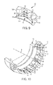
- FIG. 15 is a cross-sectional view of two pipes joined together via the flexible annular cartridge of FIG. 6 .
- FIG. 16 illustrates deflection of the two pipes of FIG. 15 .
- phrases such as “between X and Y”, “X-Y”, “between about X and Y”, and “about X-Y” should be interpreted to include X and Y.
- phrases such as “between about X and Y” and “about X-Y” mean “between about X and about Y.”
- phrases such as “from about X to Y” and “from about X-Y” mean “from about X to about Y.”
- spatially relative terms such as “under”, “below”, “lower”, “over”, “upper” and the like, may be used herein for ease of description to describe one element or feature's relationship to another element(s) or feature(s) as illustrated in the figures. It will be understood that the spatially relative terms are intended to encompass different orientations of a device in use or operation in addition to the orientation depicted in the figures. For example, if a device in the figures is inverted, elements described as “under” or “beneath” other elements or features would then be oriented “over” the other elements or features. Thus, the exemplary term “under” can encompass both an orientation of over and under.
- the device may be otherwise oriented (rotated 90 degrees or at other orientations) and the spatially relative descriptors used herein interpreted accordingly.
- the terms “upwardly”, “downwardly”, “vertical”, “horizontal” and the like are used herein for the purpose of explanation only unless specifically indicated otherwise.
- first and second are used herein to describe various features or elements, these features or elements should not be limited by these terms. These terms are only used to distinguish one feature or element from another feature or element. Thus, a first feature or element discussed below could be termed a second feature or element, and similarly, a second feature or element discussed below could be termed a first feature or element without departing from the teachings of the present invention.
- the terms “about” and “approximately” shall generally mean an acceptable degree of error or variation for the quantity measured given the nature or precision of the measurements. For example, when these terms are used in the context of durometer values they account for the lack of precision generally resulting from durometer measurements. Typical, exemplary degrees of error or variation are within 20 percent (%), preferably within 10%, and more preferably within 5% of a given value or range of values. Numerical quantities given herein are approximate unless stated otherwise, meaning that the term “about” or “approximately” can be inferred when not expressly stated.
- bell refers to the enlarged female end of a pipe configured to receive a portion of an adjoining pipe therein.
- ellipsoid refers to a closed quadric surface that is a three-dimensional analogue of an ellipse. As defined herein, a sphere is one species of ellipsoid.
- frustoellipsoidal means having the shape of a frustum of an ellipsoid, i.e. an ellipsoid that is truncated by two planes.
- frustospherical means having the shape of a frustum of a sphere, i.e. a sphere that is truncated by two planes.
- a frustoellipsoidal object may be frustospherical (and all frustospherical objects are frustoellipsoidal).
- the common abbreviation “e.g.” means “exempli gratia,” and may be used to introduce or specify a general example or examples of a previously mentioned item, and is not intended to be limiting of such item.
- a flexible annular cartridge 20 is provided for joining and sealing a bell and spigot pipe joint 1 , wherein the outer contour of the cartridge is approximately frustoellipsoidal, the cartridge 20 comprising: an annular member 30 having outer and inner surfaces ( 30 a and 30 b ) and opposite first and second ends ( 30 c and 30 d ), comprising a plurality of pipe gripping members 40 positioned on the inner surface 30 a ; a flexible annular gasket 50 having outer and inner surfaces ( 50 a and 50 b ), opposite first and second ends ( 50 c and 50 d ), and a circumferentially extending sealing lip 52 projecting inwardly from the gasket inner surface 50 a , wherein the annular member first end 30 c engages the flexible annular gasket second end 50 d ; and a backup ring 70 having a hardness that exceeds the hardness of the gasket 50 , wherein the backup ring 70 engages the gasket 50 at the gasket first end 50 c .
- the cartridge 20
- the annular cartridge 20 may be adapted to be inserted within a bell socket 14 to surround and seal a pipe spigot 10 a inserted therein.
- the illustrated annular cartridge 20 in FIGS. 3 and 4 (shown in cross-section view) is located within the bell socket 14 of pipe 12 .
- the annular member 30 and the flexible annular gasket 50 may be secured together.
- the annular member 30 may be constructed from any suitable material. Ideally it will be durable enough to retain the spigot 10 a in the socket 14 under separating forces.
- the annular member 30 is constructed from a metal material.
- the annular member 30 is constructed from ductile iron.
- the annular member 30 may also be constructed from a polymeric material sufficiently resistant to deformation to prevent extrusion of the cartridge 20 after insertion into the pipe joint 1 under operating pressure. The materials would depend on the intended operating pressure, as understood by those of ordinary skill in the art.
- the annular member 30 may include a plurality of circumferentially spaced-apart pipe gripping members or wedges 40 .
- the gripping members 40 are harder than the material from which the pipe spigot 10 a is constructed, such that the gripping members 40 will dig into the outer surface of the spigot 10 a when under a separating force.
- the gripping elements 40 may have a hardness of about 40-55 according to the ASTM E18-2000 standard employing the Rockwell C scale (this range is particularly suitable for the use of ductile iron pipe spigots).
- each pipe gripping member 40 includes a pair of adjacent teeth 42 t extending from surface 40 a thereof.
- the backup ring 70 is adjacent to the flexible annular gasket 50 .
- the gasket 50 may be constructed of any elastomeric material that is known in the art to be suitable in pipe joints carrying various fluids, such fluids including but not limited to water, treated drinking water, wastewater, natural gas, liquefied natural gas, steam, and compressed air.
- suitable elastomers for pipe joints carrying water at ambient temperatures include styrene butadiene rubber, ethylene propylene diene monomer, nitrile, and neoprene.
- the flexible annular gasket 50 includes a plurality of prongs 54 that extend outwardly from the second end 50 d thereof.
- the prongs 54 are configured to engage a respective plurality of cavities 38 formed within the annular member first end 30 c .
- each one of the plurality of prongs 54 is adhesively secured within a respective one of the plurality of cavities 38 , by virtue of an adhesive.
- a conventional push-on joint requires the gasket placed inside the bell to remain stationary during insertion of the spigot. As is frequently the case, as the spigot is pushed into the socket, it catches the gasket and dislodges it causing a leak. In some designs an annular surface, perpendicular to the longitudinal axis of the pipe, is cast within the socket as a stop for the gasket to bear against during spigot insertion to prevent the dislodging of the gasket. Applicant discovered that this function can be provided by a movable backup ring 70 ( FIGS. 3, 4 ) placed beyond the sealing gasket 50 ( FIGS. 3, 4 ) in the bottom of a socket 14 .
- the backup ring 70 may have a hardness that exceeds the hardness of the gasket 50 in order to resist “fish-mouthing” under high pressures. Some embodiments of the backup ring 70 have a hardness of at least about 70 according to the ASTM D2240 standard employing durometer type Shore A. Further embodiments of the backup ring 70 have a hardness of about 70-95 according to the ASTM D2240 standard employing durometer type Shore A. Still further embodiments of the backup ring 70 have a hardness of about 75-90 according to the ASTM D2240 standard employing durometer type Shore A. Any of the above cartridges, in a specific embodiment of the backup ring 70 has a hardness of about 80 according to the ASTM D2240 standard employing durometer type Shore A. A backup ring 70 with excessively high hardness tends to be brittle, and may crack, while a backup ring 70 with excessively low hardness will tend to deform or “fishmouth” when pressed against the socket 14 under pressure.
- this backup ring 70 serves as a stop to prevent the gasket 50 from dislodging during insertion of the spigot 10 a , yet move with the gasket 50 as deflection takes place.
- the backup ring 70 is an integral part of the cartridge 20 , and may be molded or adhered to the sealing gasket 50 and gripping members 40 , but in other embodiments it can be a separate component.
- the backup ring 70 is harder than the sealing portion of the gasket 50 .
- the backup ring 70 is flexible enough as a ring to be inserted into the bell 14 .
- the backup ring 70 includes outer and inner surfaces 70 a , 70 b , and opposite first and second ends 70 c and 70 d .
- the backup ring first end 70 c is configured to engage the flexible annular gasket first end 50 c .
- the backup ring first end 70 c matingly engages and/or adhesively engages the flexible annular gasket first end 50 c.
- the flexible annular cartridge 20 defines a longitudinal cartridge axis A and includes annular member 30 connected to flexible annular gasket 50 .
- the illustrated annular member 30 has outer and inner surfaces 30 a , 30 b and opposite first and second ends 30 c , 30 d .
- a plurality of pipe gripping members 40 are positioned on the annular member inner surface 30 b in circumferentially spaced-apart relationship.
- the annular member 30 comprise a plurality of interlocking segments 32 , each segment comprising a pipe gripping member 40 positioned to grip a surface of the pipe spigot 10 a .
- the segments 32 may be interlocked so as to allow them to flex relative to one another, although the segments 32 themselves need not be significantly flexible.
- the segmented nature of the annular member 30 allows the annular member 30 to be constructed of a hard and durable material, while still allowing the annular member 30 to deform radially as necessary for insertion into a pre-formed pipe bell 14 .
- the illustrated annular member 30 includes a plurality of circumferentially interlocking elements or segments 32 .
- each segment 32 includes inner and outer surfaces 32 a , 32 b and opposite first and second ends 32 c , 32 d .
- a male connector 34 extends outwardly from first end 32 c and a female connector 36 is located within second end 32 d , as illustrated.
- the annular member 30 is assembled by arranging the plurality of segments 32 such that a male connector 34 of an element engages a female connector 36 of an adjacent element 32 .
- the plurality of elements 32 do not require adhesive or other fastening means to remain connected as the annular member 30 . However, such adhesive or fastening means may be employed to increase the strength of the engagement between the gasket 50 and the annular member 30 .
- Each illustrated segment 32 includes a pipe gripping member 40 configured to grip a surface of a pipe spigot 10 a ( FIG. 3 ). Under external forces or internal pressure tending to withdraw the pipe end (i.e., pipe spigot 10 a ) from the bell socket 14 , the pipe gripping members 40 act against the external surface 10 b of the spigot 10 a and clamp the pipe end, preventing its withdrawal.
- each pipe gripping member 40 includes a pipe engaging face 40 a with a plurality of elongated teeth 42 t extending outwardly from the pipe engaging face 40 a in adjacent, spaced-apart relationship.
- each pipe gripping member 40 has three teeth 42 t .
- embodiments of the present gripping member 40 are not limited to the illustrated configuration.
- Various numbers of teeth 42 t including a single tooth 42 t , may be utilized.
- embodiments of the interlocking segment 32 do not require that each interlocking segment 32 have a pipe gripping member 40 .
- the annular member 30 may include any number of pipe gripping members 40 and may include even a single pipe gripping member 40 .
- each elongated tooth 42 t has an arcuate configuration that substantially conforms to an outer surface 10 b of a pipe spigot 10 a ( FIG. 3 ).
- each elongated tooth 42 t may be substantially straight (i.e., non-arcuate).
- Each of the illustrated interlocking segments 32 includes a cavity 38 formed on each side of the pipe gripping member 40 . These cavities 38 are utilized for engagement with the flexible annular gasket 50 , as will be described below.
- the interlocking segments 32 are formed from ductile iron, and may be formed via sand molded casting. However, various types of materials may be utilized, as well as various manufacturing techniques.
- the illustrated flexible annular gasket 50 includes outer and inner surfaces 50 a , 50 b , and opposite first and second ends 50 c , 50 d .
- a circumferentially extending sealing lip 52 projects inwardly from the gasket inner surface 50 b (best seen in FIG. 8 ).
- the sealing lip 52 is configured to snugly and sealingly engage the outer surface 10 b of a pipe spigot 10 a ( FIG. 3 ) inserted therethrough.
- the flexible annular gasket 50 may be formed from an elastomeric material, such as rubber, and the like.
- the illustrated annular gasket 50 includes a plurality of prongs 54 that extend outwardly from the second end 50 d .
- the prongs 54 are configured to engage a respective plurality of cavities 38 within the annular member 30 . As such, the annular member first end 30 c is secured to the flexible annular gasket second end 50 d.
- each one of the plurality of prongs 54 is adhesively secured within a respective one of the plurality of cavities 38 .
- embodiments of the present invention do not require the use of adhesive.
- the illustrated prongs 54 and the corresponding cavities 38 may have various shapes and configurations. Embodiments of the present invention are not limited to the illustrated configuration of either.
- a method of joining and sealing a bell and spigot pipe joint 1 comprising: providing a pipe socket 14 having an approximately ellipsoidal inner contour, and defining an opening 14 a and a longitudinal socket axis B; providing the flexible annular cartridge 20 as described above, defining a longitudinal cartridge axis A; orienting the cartridge 20 such that the longitudinal cartridge axis A is approximately perpendicular to the longitudinal socket axis B; inserting the cartridge 20 into the socket 14 ; and rotating the cartridge 20 such that the longitudinal cartridge axis A is approximately parallel to the longitudinal socket axis B.
- the cartridge 20 may be any disclosed in the previous sections.
- the method may further comprise inserting a pipe spigot 10 a through the cartridge 20 into the socket 14 .
- the opening 14 a defined by the socket 14 refers to the mouth of the bell, and should not be confused with any other opening on the pipe 12 connected to the socket 14 .
- the socket 14 also defines a longitudinal socket axis B, which is the axis parallel to the direction of fluid flow through the pipe joint 1 .
- the longitudinal socket axis B can also be defined as the axis that is perpendicular to the radial axes of the socket 14 .
- the flexible annular cartridge 20 defines a longitudinal cartridge axis A ( FIG. 6 ), which is the axis that is perpendicular to the radial axes of the annulus.
- the flexible properties of the cartridge 20 allow it to be deformed to decrease one of its radial dimensions so as to allow it to pass through the opening of the socket 14 to be inserted, and afterward resume its relaxed shape.
- the method may thus comprise stretching the cartridge 20 in a radial direction that is approximately parallel to the longitudinal socket axis B during insertion.
- Some embodiments of the method comprise compressing the cartridge 20 in a first radial direction prior to or during insertion, or compressing the cartridge 20 in a first radial direction and distending the cartridge 20 in a second radial direction approximately perpendicular to the first radial direction prior to or during insertion.
- the stretching, compressing, and distending of the cartridge 20 is distinct from the conventional means of inserting a thin flexible gasket by folding it in on itself, to form a saddle shape (or a C shape as seen edgewise).
- Some embodiments of the cartridge 20 of the instant disclosure are capable of flexing to increase or decrease a given radial diameter, but cannot flex to form a saddle shape or a C shape as seen edgewise. Thus they can be stretched to form an ellipse when viewed from the front.
- the flexible cartridge 20 is illustrated being placed within the bell socket 14 of a pipe 12 and ready to receive a pipe spigot 10 a therein.
- the flexible cartridge 20 is rotated ninety degrees (90°) relative to the opening 14 a of the bell socket 14 and then inserted into the bell socket 14 .
- the flexibility of the cartridge 20 allows the cartridge 20 to be deformed for insertion into the bell socket 14 .
- the cartridge 20 also has resiliency such that it returns to its former shape once inserted into the bell socket 14 . As illustrated in FIGS.
- the cartridge 20 is rotated ninety degrees (90°) relative to the opening 14 a of the bell socket 14 and such that the annular member 20 is facing outwardly.
- the annular member 30 prevents the displacement of the annular gasket 50 into the bell socket 14 during insertion of a pipe spigot 10 a of an adjoining pipe 10 .
- the end of an adjoining pipe spigot 10 a ( FIG. 15 ) is inserted into the bell socket opening 14 a and through the annular member 30 of the cartridge 20 .
- the insertion is completed when the pipe end 10 a passes through the annular gasket 50 , as illustrated in FIG. 15 .
- the pipe gripping members 40 which surround the pipe end 10 a , stabilize the cartridge 20 during insertion.
- the cartridge 20 simulates an ellipsoid or sphere and the adjoining pipe 10 can then be deflected from alignment with the axis of the first pipe 12 by as much as fifteen degrees (15°), as illustrated in FIG. 16 .
- a pipe joint 1 comprising: a pipe socket 14 having an ellipsoidal inner contour; and the flexible annular cartridge 20 as described above inserted within the socket 14 , such that the outer contour of the cartridge 20 complements the inner contour of the socket 14 , and such that the cartridge 20 is free to rotate within the socket 14 .
- the outer contour of the cartridge 20 complements the inner contour of the socket 14 such that they define roughly identical frustums of ellipses, although it is to be understood that the outer contour of the cartridge 20 will be smaller than the inner contour of the socket 14 , to a degree that will allow rotation of the cartridge 20 within the socket 14 while still allowing the socket 14 to be sealed with the cartridge 20 .
- the joint 1 may include a pipe spigot 10 a inserted within the socket 14 and through the cartridge 20 . In some such embodiments of the joint 1 the spigot 10 a is sealed by the cartridge 20 .
- the outer contour of the cartridge 20 complements the inner contour of the socket 14 such that the cartridge 20 is free to rotate with at least two degrees of freedom within the socket 14 . In further embodiments of the joint 1 , the outer contour of the cartridge 20 complements the inner contour of the socket 14 such that the cartridge 20 is free to rotate with three degrees of freedom within the socket 14 . Because the flexible annular cartridge 20 may be inserted into the bell 14 after casting, in some embodiments of the joint 1 the pipe socket 12 is an integral part of a pipe. For example, the pipe socket may be integrally cast (or otherwise manufactured) as part of the pipe 12 .
- Pipe 10 has a spigot portion 10 a that is inserted within the bell socket 14 of the other pipe 12 and through the flexible annular cartridge 20 , which grips and holds the pipe 10 .
- the bell socket 14 has an internal surface in the form of a sphere.
Abstract
Description
Claims (28)
Priority Applications (1)
| Application Number | Priority Date | Filing Date | Title |
|---|---|---|---|
| US14/437,152 US9829137B2 (en) | 2014-03-20 | 2015-03-20 | Flexible pipe joint |
Applications Claiming Priority (3)
| Application Number | Priority Date | Filing Date | Title |
|---|---|---|---|
| US201461968130P | 2014-03-20 | 2014-03-20 | |
| PCT/US2015/021788 WO2015143345A1 (en) | 2014-03-20 | 2015-03-20 | Flexible pipe joint |
| US14/437,152 US9829137B2 (en) | 2014-03-20 | 2015-03-20 | Flexible pipe joint |
Publications (2)
| Publication Number | Publication Date |
|---|---|
| US20160305592A1 US20160305592A1 (en) | 2016-10-20 |
| US9829137B2 true US9829137B2 (en) | 2017-11-28 |
Family
ID=54145393
Family Applications (1)
| Application Number | Title | Priority Date | Filing Date |
|---|---|---|---|
| US14/437,152 Active 2036-01-03 US9829137B2 (en) | 2014-03-20 | 2015-03-20 | Flexible pipe joint |
Country Status (2)
| Country | Link |
|---|---|
| US (1) | US9829137B2 (en) |
| WO (1) | WO2015143345A1 (en) |
Cited By (3)
| Publication number | Priority date | Publication date | Assignee | Title |
|---|---|---|---|---|
| US20160178098A1 (en) * | 2014-12-23 | 2016-06-23 | Winfried Felber | Device for connecting tubular pipe elements |
| US20220163156A1 (en) * | 2020-11-23 | 2022-05-26 | North American Pipe Corporation | Pipe joint insert device, pipe joint assembly, and methods of forming same |
| US11353148B2 (en) * | 2019-03-11 | 2022-06-07 | S & B Technical Services, Inc. | Sealing and restraint system for joining plastic pipe sections having pre-formed sockets |
Families Citing this family (1)
| Publication number | Priority date | Publication date | Assignee | Title |
|---|---|---|---|---|
| CN106959192B (en) * | 2017-03-22 | 2024-01-09 | 天津市久盛通达科技有限公司 | Socket type pipeline hydraulic test system |
Citations (30)
| Publication number | Priority date | Publication date | Assignee | Title |
|---|---|---|---|---|
| US2953398A (en) | 1956-05-28 | 1960-09-20 | United States Pipe Foundry | Pipe joint |
| US3724880A (en) * | 1970-07-10 | 1973-04-03 | G Seiler | Thrust safety in socket connections of pipes |
| US3963298A (en) | 1972-05-29 | 1976-06-15 | Georg Seiler | Socket connection of tubes or tubular elements, in particular of metal |
| US4138145A (en) | 1975-10-02 | 1979-02-06 | The Tungum Company Limited | Pipe couplings |
| US4336014A (en) | 1980-09-15 | 1982-06-22 | Rieber & Son A/S | System for mounting a forming element on a mandrel |
| EP0121322A1 (en) | 1983-03-02 | 1984-10-10 | AMSTED Industries Incorporated | Snap ring, boltless pipe joint |
| US4637618A (en) * | 1984-07-13 | 1987-01-20 | Vassallo Research & Development Corporation | Composite gasket and fitting including same |
| US4693483A (en) * | 1984-07-13 | 1987-09-15 | Vassallo Research & Development Corporation | Composite gasket and fitting including same |
| US4776617A (en) | 1986-02-14 | 1988-10-11 | Kabushiki Kaisha Suiken Technology | Telescopic swivel pipe joint |
| US4871197A (en) | 1988-08-15 | 1989-10-03 | United States Pipe And Foundry Company | Earthquake resistant pipe joints |
| US5476290A (en) | 1993-08-02 | 1995-12-19 | Eisenwerke Fried.Wilh.Duker Gmbh & Co. | Plug-in socket joint secured against sliding movement |
| US5897146A (en) | 1996-03-21 | 1999-04-27 | Yano Giken Co., Ltd. | Flexible pipe connector |
| US6277315B1 (en) * | 1992-03-10 | 2001-08-21 | Haallstedt Goeran | Method for manufacturing sealing rings |
| US6367802B1 (en) | 1999-11-30 | 2002-04-09 | Malcolm Mann Inc. | Annular gasket with locking structure |
| US7140618B2 (en) | 2003-01-16 | 2006-11-28 | Vassallo Research & Development Corporation | Socket with dual-functional composite gasket |
| WO2007033390A1 (en) | 2005-09-15 | 2007-03-29 | E. Hawle Armaturenwerke Gmbh | Connector piece for an end of a round in particular tubular object |
| US7284310B2 (en) * | 2004-12-07 | 2007-10-23 | S & B Technical Products, Inc. | Method of manufacturing a seal and restraining system |
| EP1881251A2 (en) | 2006-07-17 | 2008-01-23 | Semperit Aktiengesellschaft Holding | Gasket and connecting device for a socket joint |
| US7500699B2 (en) | 2001-01-19 | 2009-03-10 | Victaulic Company | Clamping mechanical pipe coupling derived from a standard fitting |
| US7774915B2 (en) | 2007-05-16 | 2010-08-17 | S & B Technical Products, Inc. | Ductile iron pressure fit gasket |
| US7806445B2 (en) | 2006-06-30 | 2010-10-05 | Tiroler Roehren- Und Metallwerke Ag | Spigot-and-socket joint |
| US20100264645A1 (en) * | 2009-04-20 | 2010-10-21 | S & B Technical Products, Inc. | Seal and Restraint System for Plastic Pipe with Low Friction Coating |
| US8096585B2 (en) | 2006-10-31 | 2012-01-17 | Saint-Gobain Pam | Tubular joint |
| CN102384324A (en) | 2011-11-11 | 2012-03-21 | 马鞍山宏力橡胶制品有限公司 | Sealing ring used for preventing disengagement of pipelines |
| US8235427B2 (en) | 2005-06-10 | 2012-08-07 | S & B Technical Products, Inc. | Self restrained ductile iron fitting |
| WO2013171223A1 (en) | 2012-05-14 | 2013-11-21 | Trelleborg Pipe Seals Lelystad BV | Pipe seal |
| JP5534821B2 (en) | 2010-01-08 | 2014-07-02 | 株式会社クボタ | Sealing material with separation prevention function and separation prevention pipe joint |
| US20140191504A1 (en) | 2013-01-04 | 2014-07-10 | Yijun WU | PVC-Coated and Adaptive Pipe Coupling |
| US20140360004A1 (en) | 2009-10-12 | 2014-12-11 | Mueller International, Llc | Self-restrained pipe joint method of assembly |
| US8925977B2 (en) | 2009-10-09 | 2015-01-06 | Mueller International, Llc | Simplified low insertion force sealing device capable of self restraint and joint deflection |
Family Cites Families (1)
| Publication number | Priority date | Publication date | Assignee | Title |
|---|---|---|---|---|
| US8544851B2 (en) * | 2010-08-24 | 2013-10-01 | Mueller International, Llc | Gasket for parabolic ramp self restraining bell joint |
-
2015
- 2015-03-20 US US14/437,152 patent/US9829137B2/en active Active
- 2015-03-20 WO PCT/US2015/021788 patent/WO2015143345A1/en active Application Filing
Patent Citations (31)
| Publication number | Priority date | Publication date | Assignee | Title |
|---|---|---|---|---|
| US2953398A (en) | 1956-05-28 | 1960-09-20 | United States Pipe Foundry | Pipe joint |
| US3724880A (en) * | 1970-07-10 | 1973-04-03 | G Seiler | Thrust safety in socket connections of pipes |
| US3963298A (en) | 1972-05-29 | 1976-06-15 | Georg Seiler | Socket connection of tubes or tubular elements, in particular of metal |
| US4138145A (en) | 1975-10-02 | 1979-02-06 | The Tungum Company Limited | Pipe couplings |
| US4336014A (en) | 1980-09-15 | 1982-06-22 | Rieber & Son A/S | System for mounting a forming element on a mandrel |
| EP0121322A1 (en) | 1983-03-02 | 1984-10-10 | AMSTED Industries Incorporated | Snap ring, boltless pipe joint |
| US4637618A (en) * | 1984-07-13 | 1987-01-20 | Vassallo Research & Development Corporation | Composite gasket and fitting including same |
| US4693483A (en) * | 1984-07-13 | 1987-09-15 | Vassallo Research & Development Corporation | Composite gasket and fitting including same |
| US4776617A (en) | 1986-02-14 | 1988-10-11 | Kabushiki Kaisha Suiken Technology | Telescopic swivel pipe joint |
| US4871197A (en) | 1988-08-15 | 1989-10-03 | United States Pipe And Foundry Company | Earthquake resistant pipe joints |
| US6277315B1 (en) * | 1992-03-10 | 2001-08-21 | Haallstedt Goeran | Method for manufacturing sealing rings |
| US5476290A (en) | 1993-08-02 | 1995-12-19 | Eisenwerke Fried.Wilh.Duker Gmbh & Co. | Plug-in socket joint secured against sliding movement |
| US5897146A (en) | 1996-03-21 | 1999-04-27 | Yano Giken Co., Ltd. | Flexible pipe connector |
| US6367802B1 (en) | 1999-11-30 | 2002-04-09 | Malcolm Mann Inc. | Annular gasket with locking structure |
| US7500699B2 (en) | 2001-01-19 | 2009-03-10 | Victaulic Company | Clamping mechanical pipe coupling derived from a standard fitting |
| US7140618B2 (en) | 2003-01-16 | 2006-11-28 | Vassallo Research & Development Corporation | Socket with dual-functional composite gasket |
| US7537248B2 (en) | 2004-12-07 | 2009-05-26 | S & B Technical Products, Inc. | Combination seal and restraint system for plastic pipe |
| US7284310B2 (en) * | 2004-12-07 | 2007-10-23 | S & B Technical Products, Inc. | Method of manufacturing a seal and restraining system |
| US8235427B2 (en) | 2005-06-10 | 2012-08-07 | S & B Technical Products, Inc. | Self restrained ductile iron fitting |
| WO2007033390A1 (en) | 2005-09-15 | 2007-03-29 | E. Hawle Armaturenwerke Gmbh | Connector piece for an end of a round in particular tubular object |
| US7806445B2 (en) | 2006-06-30 | 2010-10-05 | Tiroler Roehren- Und Metallwerke Ag | Spigot-and-socket joint |
| EP1881251A2 (en) | 2006-07-17 | 2008-01-23 | Semperit Aktiengesellschaft Holding | Gasket and connecting device for a socket joint |
| US8096585B2 (en) | 2006-10-31 | 2012-01-17 | Saint-Gobain Pam | Tubular joint |
| US7774915B2 (en) | 2007-05-16 | 2010-08-17 | S & B Technical Products, Inc. | Ductile iron pressure fit gasket |
| US20100264645A1 (en) * | 2009-04-20 | 2010-10-21 | S & B Technical Products, Inc. | Seal and Restraint System for Plastic Pipe with Low Friction Coating |
| US8925977B2 (en) | 2009-10-09 | 2015-01-06 | Mueller International, Llc | Simplified low insertion force sealing device capable of self restraint and joint deflection |
| US20140360004A1 (en) | 2009-10-12 | 2014-12-11 | Mueller International, Llc | Self-restrained pipe joint method of assembly |
| JP5534821B2 (en) | 2010-01-08 | 2014-07-02 | 株式会社クボタ | Sealing material with separation prevention function and separation prevention pipe joint |
| CN102384324A (en) | 2011-11-11 | 2012-03-21 | 马鞍山宏力橡胶制品有限公司 | Sealing ring used for preventing disengagement of pipelines |
| WO2013171223A1 (en) | 2012-05-14 | 2013-11-21 | Trelleborg Pipe Seals Lelystad BV | Pipe seal |
| US20140191504A1 (en) | 2013-01-04 | 2014-07-10 | Yijun WU | PVC-Coated and Adaptive Pipe Coupling |
Non-Patent Citations (1)
| Title |
|---|
| Lee, Jong Kyung "Written Opinion and International Search Report" Korean Intellectual Property Office; dated Jun. 23, 2015; pp. 1-26. |
Cited By (5)
| Publication number | Priority date | Publication date | Assignee | Title |
|---|---|---|---|---|
| US20160178098A1 (en) * | 2014-12-23 | 2016-06-23 | Winfried Felber | Device for connecting tubular pipe elements |
| US10781950B2 (en) * | 2014-12-23 | 2020-09-22 | Winfried Felber | Device for connecting tubular pipe elements |
| US11353148B2 (en) * | 2019-03-11 | 2022-06-07 | S & B Technical Services, Inc. | Sealing and restraint system for joining plastic pipe sections having pre-formed sockets |
| EP4111083A4 (en) * | 2019-03-11 | 2024-03-06 | S & B Technical Products Inc | Sealing and restraint system for joining plastic pipe sections having pre-formed sockets |
| US20220163156A1 (en) * | 2020-11-23 | 2022-05-26 | North American Pipe Corporation | Pipe joint insert device, pipe joint assembly, and methods of forming same |
Also Published As
| Publication number | Publication date |
|---|---|
| US20160305592A1 (en) | 2016-10-20 |
| WO2015143345A1 (en) | 2015-09-24 |
Similar Documents
| Publication | Publication Date | Title |
|---|---|---|
| US9829137B2 (en) | Flexible pipe joint | |
| US9791083B2 (en) | Fitting for joining pipe elements | |
| US10036494B2 (en) | Seal with lip projections | |
| ES2432741T3 (en) | Pipe coupling | |
| TWI660140B (en) | Coupling and seal | |
| US20090200793A1 (en) | Crown seal with integral sealing projections for undersea hydraulic couplings | |
| CN104948858A (en) | Torque retention arrangement | |
| US10041325B2 (en) | High pressure seal with composite anti-extrusion mechanism | |
| EP2372210A2 (en) | Coupling element | |
| CN104763809B (en) | Low-load double fins seal assembly | |
| US7401543B2 (en) | Pump sealing apparatus | |
| US5111879A (en) | Sanitary locking lip split well seal | |
| EP1461547B1 (en) | Components, systems and methods for forming a gasketless seal between components in an ultrahigh pressure system | |
| US245263A (en) | Fifths to ralph robb | |
| US3307854A (en) | High pressure closure | |
| KR101150212B1 (en) | Hermetic pipe connection | |
| WO2016164025A1 (en) | System and method for retaining a gasket on a sealing face | |
| AU716392B2 (en) | A seal | |
| US20200149672A1 (en) | Pipe Repair Clamp Sealing Assembly | |
| WO2016003686A1 (en) | Cap for a quick-connector coupling | |
| JP2002213666A (en) | Pipe joint structure | |
| KR20120119945A (en) | One touch type pipe connector |
Legal Events
| Date | Code | Title | Description |
|---|---|---|---|
| AS | Assignment |
Owner name: GRIFFIN PIPE PRODUCTS CO., INC., ILLINOIS Free format text: ASSIGNMENT OF ASSIGNORS INTEREST;ASSIGNOR:KENNEDY, HAROLD, JR;REEL/FRAME:035407/0366 Effective date: 20150325 |
|
| AS | Assignment |
Owner name: GRIFFIN PIPE PRODUCTS CO., LLC, ILLINOIS Free format text: ASSIGNMENT OF ASSIGNORS INTEREST;ASSIGNOR:KENNEDY, HAROLD, JR;REEL/FRAME:035724/0886 Effective date: 20150325 |
|
| AS | Assignment |
Owner name: GRIFFIN PIPE PRODUCTS CO., LLC, ILLINOIS Free format text: CORRECTIVE ASSIGNMENT TO CORRECT THE NAME OF THE ASSIGNEE PREVIOUSLY RECORDED AT REEL: 035407 FRAME: 0366. ASSIGNOR(S) HEREBY CONFIRMS THE ASSIGNMENT;ASSIGNOR:KENNEDY, HAROLD, JR;REEL/FRAME:035858/0641 Effective date: 20150325 |
|
| STCF | Information on status: patent grant |
Free format text: PATENTED CASE |
|
| AS | Assignment |
Owner name: DEUTSCHE BANK TRUST COMPANY AMERICAS, AS NOTES COLLATERAL AGENT, NEW YORK Free format text: SECURITY AGREEMENT (NOTES);ASSIGNORS:BIO CLEAN ENVIRONMENTAL SERVICES, INC.;FORTERRA CONCRETE PRODUCTS, INC.;GRIFFIN PIPE PRODUCTS COMPANY, LLC;AND OTHERS;REEL/FRAME:053229/0924 Effective date: 20200716 |
|
| MAFP | Maintenance fee payment |
Free format text: PAYMENT OF MAINTENANCE FEE, 4TH YEAR, LARGE ENTITY (ORIGINAL EVENT CODE: M1551); ENTITY STATUS OF PATENT OWNER: LARGE ENTITY Year of fee payment: 4 |
|
| AS | Assignment |
Owner name: WELLS FARGO BANK, N.A., AS AGENT, COLORADO Free format text: SECURITY INTEREST;ASSIGNOR:GRIFFIN PIPE PRODUCTS CO., LLC;REEL/FRAME:059313/0921 Effective date: 20220318 |
|
| AS | Assignment |
Owner name: FORTERRA CONCRETE PRODUCTS, INC., TEXAS Free format text: RELEASE BY SECURED PARTY;ASSIGNOR:DEUTSCHE BANK TRUST COMPANY AMERICAS, AS COLLATERAL AGENT;REEL/FRAME:060199/0286 Effective date: 20220318 Owner name: MODULAR WETLAND SYSTEMS, INC., TEXAS Free format text: RELEASE BY SECURED PARTY;ASSIGNOR:DEUTSCHE BANK TRUST COMPANY AMERICAS, AS COLLATERAL AGENT;REEL/FRAME:060199/0286 Effective date: 20220318 Owner name: FORTERRA PRECAST CONCEPTS, LLC, TEXAS Free format text: RELEASE BY SECURED PARTY;ASSIGNOR:DEUTSCHE BANK TRUST COMPANY AMERICAS, AS COLLATERAL AGENT;REEL/FRAME:060199/0286 Effective date: 20220318 Owner name: BIO CLEAN ENVIRONMENTAL SERVICES, INC., TEXAS Free format text: RELEASE BY SECURED PARTY;ASSIGNOR:DEUTSCHE BANK TRUST COMPANY AMERICAS, AS COLLATERAL AGENT;REEL/FRAME:060199/0286 Effective date: 20220318 Owner name: CUSTOM FAB, INC., TEXAS Free format text: RELEASE BY SECURED PARTY;ASSIGNOR:DEUTSCHE BANK TRUST COMPANY AMERICAS, AS COLLATERAL AGENT;REEL/FRAME:060199/0286 Effective date: 20220318 Owner name: GRIFFIN PIPE PRODUCTS CO., LLC, TEXAS Free format text: RELEASE BY SECURED PARTY;ASSIGNOR:DEUTSCHE BANK TRUST COMPANY AMERICAS, AS COLLATERAL AGENT;REEL/FRAME:060199/0286 Effective date: 20220318 Owner name: UNITED STATES PIPE AND FOUNDRY COMPANY, LLC, TEXAS Free format text: RELEASE BY SECURED PARTY;ASSIGNOR:DEUTSCHE BANK TRUST COMPANY AMERICAS, AS COLLATERAL AGENT;REEL/FRAME:060199/0286 Effective date: 20220318 Owner name: FORTERRA PIPE & PRECAST, LLC, TEXAS Free format text: RELEASE BY SECURED PARTY;ASSIGNOR:DEUTSCHE BANK TRUST COMPANY AMERICAS, AS COLLATERAL AGENT;REEL/FRAME:060199/0286 Effective date: 20220318 |
|
| AS | Assignment |
Owner name: WELLS FARGO BANK, NATIONAL ASSOCIATION, AS AGENT, GEORGIA Free format text: PATENT SECURITY AGREEMENT (ABL);ASSIGNORS:UNITED STATES PIPE AND FOUNDRY COMPANY, LLC;GRIFFIN PIPE PRODUCTS CO., LLC;CUSTOM FAB, INC.;AND OTHERS;REEL/FRAME:059479/0437 Effective date: 20220318 Owner name: WELLS FARGO BANK, NATIONAL ASSOCIATION, AS AGENT, GEORGIA Free format text: PATENT SECURITY AGREEMENT (ABL);ASSIGNORS:UNITED STATES PIPE AND FOUNDRY COMPANY, LLC;GRIFFIN PIPE PRODUCTS CO., LLC;CUSTOM FAB, INC.;AND OTHERS;REEL/FRAME:059479/0336 Effective date: 20220318 |