EP1201983A2 - Methode und Vorrichtung zum Zusammensetzen von Verbindungen zur Flüssigkeitsübertragung - Google Patents
Methode und Vorrichtung zum Zusammensetzen von Verbindungen zur Flüssigkeitsübertragung Download PDFInfo
- Publication number
- EP1201983A2 EP1201983A2 EP01308182A EP01308182A EP1201983A2 EP 1201983 A2 EP1201983 A2 EP 1201983A2 EP 01308182 A EP01308182 A EP 01308182A EP 01308182 A EP01308182 A EP 01308182A EP 1201983 A2 EP1201983 A2 EP 1201983A2
- Authority
- EP
- European Patent Office
- Prior art keywords
- coupling
- inner sleeve
- tapered
- sleeve
- diameter
- Prior art date
- Legal status (The legal status is an assumption and is not a legal conclusion. Google has not performed a legal analysis and makes no representation as to the accuracy of the status listed.)
- Granted
Links
Images

Classifications
-
- F—MECHANICAL ENGINEERING; LIGHTING; HEATING; WEAPONS; BLASTING
- F16—ENGINEERING ELEMENTS AND UNITS; GENERAL MEASURES FOR PRODUCING AND MAINTAINING EFFECTIVE FUNCTIONING OF MACHINES OR INSTALLATIONS; THERMAL INSULATION IN GENERAL
- F16L—PIPES; JOINTS OR FITTINGS FOR PIPES; SUPPORTS FOR PIPES, CABLES OR PROTECTIVE TUBING; MEANS FOR THERMAL INSULATION IN GENERAL
- F16L27/00—Adjustable joints, Joints allowing movement
- F16L27/02—Universal joints, i.e. with mechanical connection allowing angular movement or adjustment of the axes of the parts in any direction
- F16L27/026—Universal and axially displaceable joints
-
- F—MECHANICAL ENGINEERING; LIGHTING; HEATING; WEAPONS; BLASTING
- F01—MACHINES OR ENGINES IN GENERAL; ENGINE PLANTS IN GENERAL; STEAM ENGINES
- F01D—NON-POSITIVE DISPLACEMENT MACHINES OR ENGINES, e.g. STEAM TURBINES
- F01D25/00—Component parts, details, or accessories, not provided for in, or of interest apart from, other groups
-
- F—MECHANICAL ENGINEERING; LIGHTING; HEATING; WEAPONS; BLASTING
- F02—COMBUSTION ENGINES; HOT-GAS OR COMBUSTION-PRODUCT ENGINE PLANTS
- F02C—GAS-TURBINE PLANTS; AIR INTAKES FOR JET-PROPULSION PLANTS; CONTROLLING FUEL SUPPLY IN AIR-BREATHING JET-PROPULSION PLANTS
- F02C7/00—Features, components parts, details or accessories, not provided for in, or of interest apart form groups F02C1/00 - F02C6/00; Air intakes for jet-propulsion plants
-
- F—MECHANICAL ENGINEERING; LIGHTING; HEATING; WEAPONS; BLASTING
- F16—ENGINEERING ELEMENTS AND UNITS; GENERAL MEASURES FOR PRODUCING AND MAINTAINING EFFECTIVE FUNCTIONING OF MACHINES OR INSTALLATIONS; THERMAL INSULATION IN GENERAL
- F16L—PIPES; JOINTS OR FITTINGS FOR PIPES; SUPPORTS FOR PIPES, CABLES OR PROTECTIVE TUBING; MEANS FOR THERMAL INSULATION IN GENERAL
- F16L27/00—Adjustable joints, Joints allowing movement
- F16L27/12—Adjustable joints, Joints allowing movement allowing substantial longitudinal adjustment or movement
-
- F—MECHANICAL ENGINEERING; LIGHTING; HEATING; WEAPONS; BLASTING
- F05—INDEXING SCHEMES RELATING TO ENGINES OR PUMPS IN VARIOUS SUBCLASSES OF CLASSES F01-F04
- F05D—INDEXING SCHEME FOR ASPECTS RELATING TO NON-POSITIVE-DISPLACEMENT MACHINES OR ENGINES, GAS-TURBINES OR JET-PROPULSION PLANTS
- F05D2230/00—Manufacture
- F05D2230/60—Assembly methods
Definitions
- This application relates generally to couplings and, more particularly, to a couplings used to transfer fluids between two conduits within gas turbine engines.
- gas turbine engines often include flexible couplings for transferring fluids, especially cooling air, between conduits. Such couplings permit misalignment of mating hardware during installation, and permit the conduits to thermally expand during engine operation.
- One type of known coupling includes a metallic inner cylindrical sleeve including spherically formed ends. The sleeve is supported for axial and angular movement within the coupling with a pair of coupling members. The coupling members attach to the sleeve and each member includes an end containing carbon sleeves.
- the carbon sleeves include inner bores that permit the carbon sleeves to contact the spherical. ends of the sleeve to prevent fluid from leaking from the coupling between the inner sleeve and the coupling members. Because the carbon sleeves have a lower coefficient of thermal expansion in comparison to the metallic inner sleeve, the inner sleeve may expand to a greater degree than the carbon sleeve. Over time, such continued thermal expansion may lead to excessive wear of the carbon sleeves and leakage of the coupling. Over time, eventually the seals may erode completely and metal to metal contact between the sleeves may occur. Such contact potentially increases vibrations within the coupling which may in-turn lead to a failure of the coupling. Because the carbon sleeves are not serviceable, the couplings must then be replaced to prevent the coupling from leaking.
- couplings include replaceable seals. These couplings include a combination of a split seal and a continuous seal for sealing around each end of the inner sleeve. See for example U.S. Pat. No. 5,106,129.
- the assembly of such seals is complex because the continuous seal is mounted on a silicone based o-ring to provide radial pressure to the inner bore and the split seal is mounted on a split metallic ring which is further mounted on a metallic wave spring.
- Each end of the inner spring is retained in a joint end with a retaining ring inserted within a groove extending into the joint end.
- unique tools are used to radially compress the seals.
- a coupling used to transfer fluid from one conduit to another conduit includes a seal arrangement that permits an inner sleeve to move axially and angularly, relative to the conduits, without fluid leaking from the coupling.
- the coupling also includes a pair of coupling members coupled to the inner sleeve to support the inner sleeve.
- the inner sleeve includes tapered ends including retaining grooves sized to receive a seal.
- Each coupling member includes a tapered end sized to compress each inner sleeve seal during assembly of the coupling.
- the seals each include a spherical lip that is outwardly biased to provide sealable contact between the inner sleeve and the coupling first and second members.
- the seal lips ensure that sealable contact is maintained between the inner sleeve and the coupling first and second members.
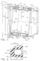
- Figure 1 is a cross-sectional view of a flexible coupling 10 used to transfer fluid under pressure from a first conduit (not shown) to a second conduit (not shown).
- coupling 10 is used to transfer fluids within gas turbine engines, such as, but not limited to, a CF6 engine available from General Electric Company, Cincinnati, Ohio.
- coupling 10 is used to transfer cooling air within a gas turbine engine.
- Coupling 10 includes an inner sleeve 12 coupled between a hollow first member 14 and a hollow second member 16.
- An axis of symmetry 18 extends between first member 14 and second member 16. Because inner sleeve 12 is permitted to move axially with respect to first and second members 14 and 16, respectively, and angularly with respect to axis of symmetry 18, coupling 10 is considered flexible with respect to the conduits.
- Inner sleeve 12 has a bore 22 therethrough, and includes a first end 30, a second end 32, and a body 34 extending therebetween.
- inner sleeve 12 is metallic and is fabricated from, but not limited to, stainless steel.
- Body 34 is substantially cylindrical and has a diameter 36 measured with respect to an outer surface 38 of inner sleeve 12. Outer surface 38 extends over first end 30, body 34, and second end 32. Body first diameter 36 is constant between first end 30 and second end 32.
- Inner sleeve 12 also includes an inner surface 40 that extends between first end 30 and second end 32.
- Inner sleeve first end 30 extends from inner sleeve body 34 and is outwardly tapered from axis of symmetry 18 and with respect to inner sleeve body 34. Accordingly, inner sleeve first end 30 has a diameter 46 that is larger than inner sleeve body diameter 36. In an alternative embodiment, inner sleeve first end 30 is not outwardly tapered from axis of symmetry 18 and first end diameter 46 is not larger than inner sleeve body diameter 36. Inner sleeve first end 30 tapers outwardly from inner sleeve body 34 a distance 50 from an outer edge 52 of inner sleeve 12.
- An annular projection 54 extends radially outward from inner sleeve outer surface 38. More specifically, projection 54 extends outwardly from inner sleeve first end 30 a distance 56 and is substantially perpendicularly to inner sleeve outer surface 38. Projection 54 is distance 50 from inner sleeve outer edge 52.
- annular lip 60 also extends radially outward from inner sleeve outer surface 38. Annular lip 60 is adjacent inner sleeve outer edge 52. In one embodiment, annular lip 60 is formed as a result of machining inner sleeve outer surface 38 around inner sleeve tapered first end 30. A retaining groove 62 is defined between annular projection 54 and annular lip 60.
- Inner sleeve 12 is symmetrical and inner sleeve second end 32 is identical to inner sleeve first end 30. Specifically, inner sleeve second end 32 extends from inner sleeve body 34 and is outwardly tapered to diameter 46. In an alternative embodiment, inner sleeve second end 32 is not outwardly tapered. Additionally, inner sleeve second end 32 also includes annular projection 54 and annular lip 60.
- coupling first member 14 is substantially cylindrical and includes a first end 70, a second end 72, and a body 74 extending therebetween.
- First member body 74 has a diameter 76.
- Diameter 76 extends across first member body 74 between inner surfaces 78 of first member body 74.
- First member diameter 76 is larger than inner sleeve body outer diameter 36 and inner sleeve first and second end diameters 46. Accordingly, first member body 74 is sized to receive inner sleeve 12.
- Coupling first member first end 70 tapers outwardly from first member body 74 to permit coupling with the first conduit.
- coupling second member 16 couples with the first conduit.
- the first conduit is a 4.0 inch diameter tube.
- Coupling first member first end 70 has a diameter 80 that is larger than body diameter 76.
- first member first end 70 mechanical couples with the first conduit using mating hardware (not shown), such as, but not limited to V-flange type hardware.
- first member first end 70 is welded to the first conduit.
- first member first end 70 permits a face seal connection to be made with the first conduit.
- Coupling first member second end 72 tapers outwardly from first member body 74 to a diameter 84 to permit coupling with inner sleeve 12. Second end diameter 84 is larger than coupling first member body diameter 76.
- first member second end 72 is attached to first member body 74 with welding. In an alternative embodiment, first member second end 72 is integrally machined into coupling first member 14.
- Coupling first member second end 72 includes an annular groove 88 extending into an inner surface 90 of first member second end 72.
- Groove 88 is adjacent an outer edge 92 of coupling first member second end 72 and is sized to receive a retainer 94.
- Retainer 94 limits an amount of axial travel or angulation of inner sleeve 12 between coupling first member 14 and coupling second member 16.
- retainer 94 is an annular one-piece retainer (not shown).
- retainer 94 is a split snap ring sized to insert within second end groove 88 and curved to extend towards coupling first member first end 70.
- retainer 94 includes a frusto-conical spacer (not shown in Figure 1) to limit an amount of travel of inner sleeve 12.
- coupling second member 16 is substantially cylindrical and includes a first end 100, a second end 102, and a body 104 extending therebetween.
- coupling second member 16 is identical with coupling first member 14.
- Second member body 104 has a diameter 106 measured with respect to an inner surface 108 of second member body 104.
- Second member body diameter 106 is larger than inner sleeve body outer diameter 36 and inner sleeve first and second end diameters 46. Accordingly, second member body 104 is sized to receive inner sleeve 12.
- Second member body 104 tapers inwardly to permit coupling with the second conduit.
- the second conduit is a 2.5 inch tube.
- Body 104 extends to second member second end 102 such that second member second end 102 has a diameter 110 smaller than second member body diameter 106.
- second member second end 102 couples mechanically with the second conduit using a welding connection.
- second member second end 102 is integrally machined into coupling second member 16.
- second member second end 102 permits mechanical coupling with the second conduit using mating hardware, such as, but not limited to, V-type flanges.
- second member second end 102 attaches with a face seal connection to the second conduit.
- Coupling second member first end 100 tapers outwardly from second member body 104 to couple with inner sleeve 12.
- coupling second member first end 100 is identical coupling first member second end 72 and is attached to second member body 104 with welding. Accordingly, coupling second member first end 100 includes annular groove 88, retainer 94, and has diameter 84.
- a pair of seals 120 and 122 permit inner sleeve 12 to be coupled in sealable contact with first and second members 14 and 16, respectively.
- Seals 120 and 122 are identical and are between inner sleeve outer surface 38 and first and second member body inner surfaces 78 and 108, respectively. More specifically, seal 120 is between inner sleeve first end 30 and first member body 74, and seal 122 is between inner sleeve second end 32 and second member body 104.
- Seals 120 and 122 permit inner sleeve 12 to move axially between first and second members 14 and 16 and to angulate with respect to coupling axis of symmetry 18 while maintaining sealable contact between respective coupling members 14 and 16, and inner sleeve 12.
- Seals 120 extend circumferentially around inner sleeve 12 and are constrained position around inner sleeve 12 between inner sleeve annular projections 54 and annular lips 60 within retaining groove 62.
- Groove 62 has a width 124 extending between projection 54 and lip 60 that is slightly wider than a free state diameter (not shown) of seals 120 and 122.
- seals 120 and 122 are installed circumferentially around each respective inner sleeve end 30 and 32 such that each seal 120 and 122 snaps over each annular lip 60 and is constrained within retaining groove 62. Because retaining groove width 124 is slightly larger than the seal free state diameter, a lip (not shown in Figure 1) of each seal 120 and 122 is not damaged during assembly. Inner sleeve annular projections 54 ensure seals 120 and 122 are positioned within retaining groove 62 and maintain seals 120 and 122 in an axial position relative to inner sleeve outer edge 52.
- Each end 30 and 32 of inner sleeve 12 is then inserted into a respective first and second member 14 and 16. More specifically, inner sleeve first end 30 is inserted within coupling first member tapered second end 72 and inner sleeve second end 32 is inserted within coupling second member tapered first end 100. As each end 30 and 32 is inserted, tapered ends 72 and 100, respectively, circumferentially compress each seal 120 and 122, respectively, and permit each seal 120 and 122 to remain in sealable contact between inner sleeve outer surface 38 and first and second member inner surfaces 78 and 108.
- Retainers 94 are then installed within first and second member grooves 88 to prevent seals 120 and 122 from emerging from beneath first and second ends 72 and 100. Coupling 10 is then attached between the first and second conduits.
- coupling inner sleeve 12 is permitted to move axially and to angulate between the first and second conduits.
- seals 120 and 122 remain in sealable contact to prevent leakage from escaping from coupling 10.
- retainers 94 contact inner sleeve annular projections 54 to limit an amount of axial movement and angulation of inner sleeve 12 between first and second coupling members 14 and 16.
- first and second conduits may be aligned non-concentrically relative to each other and coupling 10 may still be used to couple the first and second conduits for transferring fluid.
- FIG 2 is an enlarged cross-sectional view of seal 122 taken along area 2 shown in Figure 1.
- Seal 122 is a spring energized seal.
- seal 122 is a spring energized fluoropolymer seal available from American Variseal Corporation, Broomfield, Colorado.
- Seal 122 is identical to seal 120 (shown in Figure 1) and each includes a spring cavity 140, a coil 142, and a retaining surface 144. Retaining surface 144 defines spring cavity 140 and coil 142 is positioned within spring cavity 140.
- Retaining surface 144 includes a substantially U-shaped body 146 including an outer surface 148.
- Body 146 has free state width 150 measured between a closed side edge 152 and an opening side edge 154. Width 150 is less than retaining groove width 124 (shown in Figure 1).
- Outer surface 148 includes a wiper lip 160 and a rounded shoulder 162.
- Wiper lip 160 and rounded shoulder 162 function in combination to ensure seal 120 maintains sealing contact with respective coupling first and second members 14 and 16 (shown in Figure 1) despite axial or angular movement of inner sleeve 12 (shown in Figure 1), thus facilitating an elimination of leakage between inner sleeve 12 and each coupling member 14 and 16.
- Wiper lip 160 is substantially spherical-shaped and is adjacent opening side edge 154.
- Wiper lip 160 has a diameter 164 that is slightly larger than first member body diameter 76 and second member body diameter 106. Because wiper lip diameter 164 is larger than body diameters 76 and 106, wiper lip 160 maintains sealable contact with respective coupling first and second members 14 and 16 despite axial or angular movement of inner sleeve 12.
- seals 120 and 122 are installed circumferentially around inner sleeve 12 such that each seal 120 and 122 is oriented within a respective retaining groove 124 such that each retaining surface closed side edge is adjacent annular projection 54 (shown in Figure 1).
- Figure 3 is an enlarged cross-sectional view of retainer 94 taken along area 3 shown in Figure 1.
- Coupling first member second end 72 includes annular groove 88 extending into first member second end inner surface 90.
- Groove 88 is adjacent coupling first member second end outer edge 92 and is sized to receive retainer 94.
- Retainer 94 limits an amount of axial travel or angulation of inner sleeve 12 (shown in Figure 1) between coupling first member 14 and coupling second member 16 (shown in Figure 1).
- retainer 94 is an annular one-piece retainer (not shown).
- retainer 94 is a split snap ring sized to insert within second end groove 88 and curved to extend towards coupling first member first end 70 (shown in Figure 1).
- Retainers 94 are then installed within first and second member grooves 88 to prevent seals 120 and 122 (shown in Figures 1 and 2) emerging from beneath first and second ends 72 and 100 (shown in Figure 1). Coupling 10 is then attached between the first and second conduits (not shown).
- FIG 4 is an enlarged cross-sectional view of an alternative embodiment of a retainer 200 that may be used with coupling 10 shown in Figure 1.
- Coupling first member second end 72 includes annular groove 88 extending into first member second end inner surface 90.
- Groove 88 is adjacent coupling first member second end outer edge 92 and is sized to receive retainer 94.
- Retainer 200 limits an amount of axial travel or angulation of inner sleeve 12 (shown in Figure 1) between coupling first member 14 and coupling second member 16 (shown in Figure 1).
- Retainer 200 extends from groove 88 substantially perpendicularly to axis of symmetry 18 (shown in Figure 1) and is adjacent a frusto-conical spacer 202. Spacer 202 is between retainer 200 and annular projection 54 (shown in Figure 1) to limit an amount of travel of inner sleeve 12 (shown in Figure 1).
- spacers 202 are installed within first and second member grooves 88 and then retainers 200 are installed to prevent seals 120 and 122 (shown in Figures 1 and 2) from emerging from beneath first and second ends 72 and 100 (shown in Figure 1). Coupling 10 is then attached between the first and second conduits (not shown).
- the above-described coupling is cost-effective and highly reliable.
- the coupling includes an inner sleeve including tapered ends.
- a single seal circumscribes each inner sleeve tapered end and each seal includes a spherical lip.
- the seal spherical lips permit the inner sleeve to remain in sealable contact within the coupling members despite axial or angular movement of the inner sleeve relative to the coupling members.
- fluid leakage from the coupling in comparison to known couplings is reduced.
- each coupling member includes a tapered end, each seal is automatically compressed as the coupling is assembled. As a result, assembly of the coupling is simplified in comparison to known coupling assemblies.
- a coupling is provided which is cost-effective and highly reliable.
Applications Claiming Priority (2)
| Application Number | Priority Date | Filing Date | Title |
|---|---|---|---|
| US670999 | 2000-09-27 | ||
| US09/670,999 US6709024B1 (en) | 2000-09-27 | 2000-09-27 | Method and apparatus for assembling couplings for transferring fluids |
Publications (3)
| Publication Number | Publication Date |
|---|---|
| EP1201983A2 true EP1201983A2 (de) | 2002-05-02 |
| EP1201983A3 EP1201983A3 (de) | 2002-05-15 |
| EP1201983B1 EP1201983B1 (de) | 2009-03-11 |
Family
ID=24692742
Family Applications (1)
| Application Number | Title | Priority Date | Filing Date |
|---|---|---|---|
| EP01308182A Expired - Lifetime EP1201983B1 (de) | 2000-09-27 | 2001-09-26 | Methode und Vorrichtung zum Zusammensetzen von Verbindungen zur Flüssigkeitsübertragung |
Country Status (4)
| Country | Link |
|---|---|
| US (1) | US6709024B1 (de) |
| EP (1) | EP1201983B1 (de) |
| JP (1) | JP5099949B2 (de) |
| DE (1) | DE60137896D1 (de) |
Cited By (3)
| Publication number | Priority date | Publication date | Assignee | Title |
|---|---|---|---|---|
| WO2009129946A1 (de) * | 2008-04-25 | 2009-10-29 | Rehau Ag + Co | Gelenkmuffe für rohre |
| CN102927273A (zh) * | 2011-08-08 | 2013-02-13 | 科德宝两合公司 | 密封件及由此得到的密封装置 |
| EP3910224A1 (de) * | 2020-05-15 | 2021-11-17 | Roller Bearing Company of America, Inc. | Flexible ausrichtungsdichtungskupplung |
Families Citing this family (12)
| Publication number | Priority date | Publication date | Assignee | Title |
|---|---|---|---|---|
| GB2385643B (en) * | 2002-02-20 | 2005-05-18 | Cross Mfg Company | Improvements relating to a fluid seal |
| DE202004002665U1 (de) * | 2004-02-20 | 2004-09-02 | Suevia Haiges Gmbh | Tränkvorrichtung mit einer Heizeinrichtung |
| US20070045166A1 (en) * | 2005-08-26 | 2007-03-01 | General Electric Company | Compliant connector for ECCS strainer modules |
| US20090079186A1 (en) * | 2007-09-24 | 2009-03-26 | Honeywell International, Inc. | Flexible fitting for rigid tubing assembly |
| US8490409B2 (en) * | 2009-10-01 | 2013-07-23 | Pratt & Whitney Canada Corp. | Bleed air transfer tube |
| DE102013007443A1 (de) * | 2013-04-30 | 2014-10-30 | Rolls-Royce Deutschland Ltd & Co Kg | Brennerdichtung für Gasturbinen-Brennkammerkopf und Hitzeschild |
| JP2015105736A (ja) * | 2013-12-02 | 2015-06-08 | カヤバ工業株式会社 | シール装置 |
| DE102014000465A1 (de) * | 2014-01-16 | 2015-07-16 | Mtu Friedrichshafen Gmbh | Ladeluftleitung |
| FR3024179B1 (fr) * | 2014-07-25 | 2016-08-26 | Snecma | Systeme d'alimentation en air sous pression installe dans une turbomachine d'aeronef comportant des moyens d'etancheite |
| DE102016226019B4 (de) * | 2016-12-22 | 2022-12-15 | Mahle International Gmbh | Kupplungselement einer Kurbelgehäuseentlüftungseinrichtung |
| CA3133211A1 (en) * | 2019-03-19 | 2020-09-24 | Saipem S.P.A. | Pipeline telescopic joint |
| CN109869552A (zh) * | 2019-04-19 | 2019-06-11 | 中国航发湖南动力机械研究所 | 一种空气管路连接装置 |
Citations (2)
| Publication number | Priority date | Publication date | Assignee | Title |
|---|---|---|---|---|
| US3405957A (en) * | 1967-04-03 | 1968-10-15 | Richard O. Chakroff | Flexible tube coupling |
| EP0797040A2 (de) * | 1996-03-21 | 1997-09-24 | Yano Giken Co., Ltd. | Flexible Rohrverbindung |
Family Cites Families (20)
| Publication number | Priority date | Publication date | Assignee | Title |
|---|---|---|---|---|
| US10617A (en) * | 1854-03-07 | Connecting the joints of air-heating pipes | ||
| US951704A (en) * | 1906-12-14 | 1910-03-08 | Charles R Schmidt | Pipe-coupling. |
| US2323823A (en) * | 1942-07-10 | 1943-07-06 | Pollak Mfg Company | Joint for exhaust manifold systems |
| US2804559A (en) * | 1952-01-29 | 1957-08-27 | Clarence T Brewer | Housing for motor or other apparatus |
| US3414299A (en) * | 1965-12-17 | 1968-12-03 | Holmberg Inc | Pipe couplings |
| US3596934A (en) * | 1969-05-06 | 1971-08-03 | Herbert A De Cenzo | Flexible fluidtight coupling for tubes |
| US3787079A (en) * | 1972-04-13 | 1974-01-22 | Gen Connector Corp | Sealing connection for conduit couplings |
| US4150847A (en) * | 1976-06-04 | 1979-04-24 | Cenzo Herbert A De | Flexible tube coupling with symmetrical anchor ring |
| US4066281A (en) * | 1976-07-16 | 1978-01-03 | Bonis John C De | Porsche automobile oil drain replacement tube |
| DE2814497C2 (de) * | 1978-03-31 | 1982-03-25 | Wilhelm Dipl.-Ing. 1000 Berlin Fischer | Muffeninnendichtung für Rohrstöße bei Rohrleitungen |
| US4475750A (en) * | 1982-02-02 | 1984-10-09 | Campbell Joseph K | Pipe stress/strain neutralizer with hydraulically balanced spherical element |
| US4522433A (en) * | 1982-05-14 | 1985-06-11 | Stanley Aviation Corporation | Spherical seat flexible O-ring coupling |
| US4676241A (en) * | 1984-01-16 | 1987-06-30 | W.L.G. Technology | Ventilation tube swivel |
| US5106129A (en) | 1990-10-09 | 1992-04-21 | Delaware Capital Formation, Inc. | Flexible coupling for transferring a fluid between two fluid conduits |
| US5354104A (en) | 1993-01-15 | 1994-10-11 | Techlam | Flexible coupling for pipework |
| US5507535A (en) * | 1995-01-09 | 1996-04-16 | Mckamey; Floyd | Conduit swivel connector |
| AU3488495A (en) | 1995-07-28 | 1997-02-26 | Kvaerner Pulping Technologies Ab | Expansion unit for piping adjustment |
| US5772254A (en) | 1995-12-20 | 1998-06-30 | Eg&G Pressure Science, Inc. | Modular joint, with a replaceable sealing sleeve |
| FR2771452B1 (fr) | 1997-11-21 | 2000-04-14 | Aerospatiale | Dispositif de degivrage pour capot d'entree d'air de moteur a reaction |
| US6179339B1 (en) | 1999-09-15 | 2001-01-30 | Smail Vila | Seal rings for low loss flexible coupling of gas conduits |
-
2000
- 2000-09-27 US US09/670,999 patent/US6709024B1/en not_active Expired - Lifetime
-
2001
- 2001-09-26 JP JP2001292703A patent/JP5099949B2/ja not_active Expired - Fee Related
- 2001-09-26 DE DE60137896T patent/DE60137896D1/de not_active Expired - Lifetime
- 2001-09-26 EP EP01308182A patent/EP1201983B1/de not_active Expired - Lifetime
Patent Citations (2)
| Publication number | Priority date | Publication date | Assignee | Title |
|---|---|---|---|---|
| US3405957A (en) * | 1967-04-03 | 1968-10-15 | Richard O. Chakroff | Flexible tube coupling |
| EP0797040A2 (de) * | 1996-03-21 | 1997-09-24 | Yano Giken Co., Ltd. | Flexible Rohrverbindung |
Cited By (6)
| Publication number | Priority date | Publication date | Assignee | Title |
|---|---|---|---|---|
| WO2009129946A1 (de) * | 2008-04-25 | 2009-10-29 | Rehau Ag + Co | Gelenkmuffe für rohre |
| CN102927273A (zh) * | 2011-08-08 | 2013-02-13 | 科德宝两合公司 | 密封件及由此得到的密封装置 |
| EP2557347A3 (de) * | 2011-08-08 | 2014-01-22 | Carl Freudenberg KG | Dichtung und Dichtungsanordnung damit |
| US9016698B2 (en) | 2011-08-08 | 2015-04-28 | Carl Freudenberg Kg | Seal and associated sealing arrangement |
| CN102927273B (zh) * | 2011-08-08 | 2016-03-02 | 科德宝两合公司 | 密封件及由此得到的密封装置 |
| EP3910224A1 (de) * | 2020-05-15 | 2021-11-17 | Roller Bearing Company of America, Inc. | Flexible ausrichtungsdichtungskupplung |
Also Published As
| Publication number | Publication date |
|---|---|
| EP1201983A3 (de) | 2002-05-15 |
| DE60137896D1 (de) | 2009-04-23 |
| JP2002250204A (ja) | 2002-09-06 |
| US6709024B1 (en) | 2004-03-23 |
| EP1201983B1 (de) | 2009-03-11 |
| JP5099949B2 (ja) | 2012-12-19 |
Similar Documents
| Publication | Publication Date | Title |
|---|---|---|
| US6709024B1 (en) | Method and apparatus for assembling couplings for transferring fluids | |
| US4553775A (en) | Resilient annular seal with supporting liner | |
| US6926284B2 (en) | Sealing arrangements | |
| US3724878A (en) | Flexible connector | |
| EP1639202B1 (de) | Flexible Kupplung mit einem federbelasteten L-förmigen Dichtungsring | |
| US4448449A (en) | Flexible piping joint and method of forming same | |
| US6468033B1 (en) | Methods and apparatus for maintaining alignment of borescope plungers | |
| EP0770810B1 (de) | Rohrkompensator | |
| CA2714826C (en) | Bleed air transfer tube | |
| GB2384281A (en) | A Universal Slide Joint | |
| BR0304249B1 (pt) | Conjunto, aparelho e dispositivo de vedação para um componente de acoplamento hidráulico submarino | |
| US5772254A (en) | Modular joint, with a replaceable sealing sleeve | |
| JPH07253023A (ja) | 接続導管 | |
| WO1993006395A1 (en) | An improved seal rotor | |
| EP0177650A1 (de) | Abdichtung eines Zylinderendes | |
| US6918598B2 (en) | Hot air seal | |
| US6179339B1 (en) | Seal rings for low loss flexible coupling of gas conduits | |
| US5098133A (en) | Tube coupling with swivelable piston | |
| US20050109406A1 (en) | Zero flow fireproof quick disconnect coupling | |
| CN107061744A (zh) | 弹簧加能气缸衬套密封件 | |
| US5931476A (en) | Seal with extended wear sleeve | |
| US20210356062A1 (en) | Flexible alignment sealing coupling | |
| JP3864359B2 (ja) | メカニカルシール | |
| EP4086496A1 (de) | Übertragungsrohr-baugruppe | |
| US20230022280A1 (en) | Tube coupling |
Legal Events
| Date | Code | Title | Description |
|---|---|---|---|
| PUAI | Public reference made under article 153(3) epc to a published international application that has entered the european phase |
Free format text: ORIGINAL CODE: 0009012 |
|
| PUAL | Search report despatched |
Free format text: ORIGINAL CODE: 0009013 |
|
| AK | Designated contracting states |
Kind code of ref document: A2 Designated state(s): AT BE CH CY DE DK ES FI FR GB GR IE IT LI LU MC NL PT SE TR |
|
| AX | Request for extension of the european patent |
Free format text: AL;LT;LV;MK;RO;SI |
|
| AK | Designated contracting states |
Kind code of ref document: A3 Designated state(s): AT BE CH CY DE DK ES FI FR GB GR IE IT LI LU MC NL PT SE TR |
|
| AX | Request for extension of the european patent |
Free format text: AL;LT;LV;MK;RO;SI |
|
| 17P | Request for examination filed |
Effective date: 20021115 |
|
| AKX | Designation fees paid |
Designated state(s): DE FR GB IT |
|
| 17Q | First examination report despatched |
Effective date: 20080409 |
|
| GRAP | Despatch of communication of intention to grant a patent |
Free format text: ORIGINAL CODE: EPIDOSNIGR1 |
|
| GRAS | Grant fee paid |
Free format text: ORIGINAL CODE: EPIDOSNIGR3 |
|
| GRAA | (expected) grant |
Free format text: ORIGINAL CODE: 0009210 |
|
| AK | Designated contracting states |
Kind code of ref document: B1 Designated state(s): DE FR GB IT |
|
| REG | Reference to a national code |
Ref country code: GB Ref legal event code: FG4D |
|
| REF | Corresponds to: |
Ref document number: 60137896 Country of ref document: DE Date of ref document: 20090423 Kind code of ref document: P |
|
| PLBE | No opposition filed within time limit |
Free format text: ORIGINAL CODE: 0009261 |
|
| STAA | Information on the status of an ep patent application or granted ep patent |
Free format text: STATUS: NO OPPOSITION FILED WITHIN TIME LIMIT |
|
| 26N | No opposition filed |
Effective date: 20091214 |
|
| REG | Reference to a national code |
Ref country code: FR Ref legal event code: PLFP Year of fee payment: 15 |
|
| PGFP | Annual fee paid to national office [announced via postgrant information from national office to epo] |
Ref country code: GB Payment date: 20150928 Year of fee payment: 15 |
|
| PGFP | Annual fee paid to national office [announced via postgrant information from national office to epo] |
Ref country code: FR Payment date: 20150917 Year of fee payment: 15 |
|
| PGFP | Annual fee paid to national office [announced via postgrant information from national office to epo] |
Ref country code: IT Payment date: 20150923 Year of fee payment: 15 |
|
| PGFP | Annual fee paid to national office [announced via postgrant information from national office to epo] |
Ref country code: DE Payment date: 20150929 Year of fee payment: 15 |
|
| REG | Reference to a national code |
Ref country code: DE Ref legal event code: R119 Ref document number: 60137896 Country of ref document: DE |
|
| GBPC | Gb: european patent ceased through non-payment of renewal fee |
Effective date: 20160926 |
|
| REG | Reference to a national code |
Ref country code: FR Ref legal event code: ST Effective date: 20170531 |
|
| PG25 | Lapsed in a contracting state [announced via postgrant information from national office to epo] |
Ref country code: GB Free format text: LAPSE BECAUSE OF NON-PAYMENT OF DUE FEES Effective date: 20160926 Ref country code: DE Free format text: LAPSE BECAUSE OF NON-PAYMENT OF DUE FEES Effective date: 20170401 Ref country code: FR Free format text: LAPSE BECAUSE OF NON-PAYMENT OF DUE FEES Effective date: 20160930 |
|
| PG25 | Lapsed in a contracting state [announced via postgrant information from national office to epo] |
Ref country code: IT Free format text: LAPSE BECAUSE OF NON-PAYMENT OF DUE FEES Effective date: 20160926 |