EP0797026B1 - Entraínement par friction de roues - Google Patents
Entraínement par friction de roues Download PDFInfo
- Publication number
- EP0797026B1 EP0797026B1 EP97104664A EP97104664A EP0797026B1 EP 0797026 B1 EP0797026 B1 EP 0797026B1 EP 97104664 A EP97104664 A EP 97104664A EP 97104664 A EP97104664 A EP 97104664A EP 0797026 B1 EP0797026 B1 EP 0797026B1
- Authority
- EP
- European Patent Office
- Prior art keywords
- friction wheel
- friction
- driven
- wheel drive
- disc
- Prior art date
- Legal status (The legal status is an assumption and is not a legal conclusion. Google has not performed a legal analysis and makes no representation as to the accuracy of the status listed.)
- Expired - Lifetime
Links
- 230000007935 neutral effect Effects 0.000 claims description 15
- 230000033001 locomotion Effects 0.000 claims description 10
- 238000002485 combustion reaction Methods 0.000 claims description 4
- 230000005540 biological transmission Effects 0.000 description 5
- 230000002441 reversible effect Effects 0.000 description 4
- 210000003205 muscle Anatomy 0.000 description 3
- 238000013459 approach Methods 0.000 description 2
- 238000012423 maintenance Methods 0.000 description 2
- 241001417527 Pempheridae Species 0.000 description 1
- 238000000034 method Methods 0.000 description 1
Images


Classifications
-
- F—MECHANICAL ENGINEERING; LIGHTING; HEATING; WEAPONS; BLASTING
- F16—ENGINEERING ELEMENTS AND UNITS; GENERAL MEASURES FOR PRODUCING AND MAINTAINING EFFECTIVE FUNCTIONING OF MACHINES OR INSTALLATIONS; THERMAL INSULATION IN GENERAL
- F16H—GEARING
- F16H15/00—Gearings for conveying rotary motion with variable gear ratio, or for reversing rotary motion, by friction between rotary members
- F16H15/02—Gearings for conveying rotary motion with variable gear ratio, or for reversing rotary motion, by friction between rotary members without members having orbital motion
-
- Y—GENERAL TAGGING OF NEW TECHNOLOGICAL DEVELOPMENTS; GENERAL TAGGING OF CROSS-SECTIONAL TECHNOLOGIES SPANNING OVER SEVERAL SECTIONS OF THE IPC; TECHNICAL SUBJECTS COVERED BY FORMER USPC CROSS-REFERENCE ART COLLECTIONS [XRACs] AND DIGESTS
- Y10—TECHNICAL SUBJECTS COVERED BY FORMER USPC
- Y10S—TECHNICAL SUBJECTS COVERED BY FORMER USPC CROSS-REFERENCE ART COLLECTIONS [XRACs] AND DIGESTS
- Y10S56/00—Harvesters
- Y10S56/22—Underslung yieldable rotary mower
Definitions
- the invention relates to a friction wheel drive according to the preamble of claim 1 or 2.
- Friction wheel drives or friction wheel gears are transmission elements that can be produced cost-effectively and usually consist of friction wheels or friction discs with smooth surfaces that are pressed against each other in such a way that the resulting friction forces or Torques are transmitted.
- Handheld snow clearers are one application (John Deere publication from August 1994 entitled: John Deere Snow Removal Equipment).
- a friction wheel is arranged on a horizontal shaft is optionally brought into contact against a friction disc, which is from the output shaft driven by an engine.
- the friction wheel rotates with the disc and serves to drive it from wheels to chains and sprockets.
- the friction wheel can be in a neutral position in which the operator can adjust it so that there is no contact with the disc is more.
- AU-B-573971 shows a lawn tractor with a reversible gear.
- the gear has an input shaft, in each end of which a friction wheel is attached.
- the Friction wheels can interact with a friction disc in such a way that drivable wheels of the Lawn tractor, depending on which of the friction wheels the friction disc cooperates, are driven in the forward or backward direction.
- the object to be achieved with the invention is seen in a friction wheel drive provide that is simple and has fewer parts.
- the task looks in one aspect that the travel paths for reversing the direction are kept relatively small.
- the invention therefore provides that on the drivable shaft at a distance from the first A second friction disc is provided and that the friction wheel between three Positions can be pivoted such that the friction wheel in the first position against the first Friction disc abuts and can be driven in a first direction of rotation that the friction wheel in the second position against the second friction disc and in a second of the first Direction of rotation opposite to the direction of rotation is drivable and that the friction wheel in the third position to the first and second friction disc spacing and not drivable is.
- the invention provides that on the driven part at a distance from the first A second friction disc is provided and that the friction wheel between three Positions can be pivoted or the output part can be adjusted such that the first The friction disc rests in the first position against the friction wheel and in a first Direction of rotation is drivable that the second friction disc in the second position against the Friction wheel abuts and in a second direction of rotation opposite to the first direction of rotation is drivable and that the first and the second friction disc in the third position to the The friction wheel are at a distance and cannot be driven.
- This alternative is one in itself Inversion of the first solution. Both solutions have a swiveling friction wheel that is driven once and can also be driven on the other. Alternatively, you can the friction discs are adjusted.
- Friction wheel drives can also be easily installed in vehicles, especially vehicles use for lawn and property maintenance and there not only for the wheel drive.
- Such devices are usually provided with drivable components that Belt drives are driven, which is why it is further proposed according to the invention that at least one friction disc is designed as a pulley on the other hand especially in vehicles that can be used in lawn and property maintenance Power flow from the engine to the transmission via a belt drive.
- Such vehicles then have one connected to the motor and mostly directed vertically downwards Drive shaft on which a pulley for driving the tools of the device and if necessary, a pulley is provided for the power transmission to the transmission.
- the invention now uses this drive shaft for the friction wheel drive, since according to the invention it is also proposed that the drivable shaft for driving the drive wheels of a Vehicle and for driving the tools of the device is used, the device to the Vehicle is connected adjustable in height.
- the additional for the friction wheel drive necessary parts thus consist only of the friction wheel with its shaft, since the Depending on their outer diameter, pulleys can also serve as a friction disc.
- the friction wheel is then to be provided between the two pulleys and only needs to to be swiveled up or down to rotate in different directions to be driven.
- the friction wheel is then in an intermediate position, in who has no contact with the disks, his drive is interrupted.
- the friction wheel drive be used as a lifting device is used, which is why the output part of the friction wheel drive to a lifting device for Raising and lowering a device depending on the direction of rotation of the Friction wheel drive is connected.
- the device for example raised when the driven part rotates in one direction of rotation and lowered when the driven part rotates in the opposite direction.
- the lifting movement is interrupted or lifting or lowering ends. It can be used on hydraulic cylinders or complex Linkage devices that have been used to raise and lower a work tool many times were used, are waived. Also does not need to adjust the height of the device Muscle power to be used.
- the drive section can work like a winch to raise and lower the device.
- the stripping part cooperates with a sliding part that the Rotational movement of the driven part in a direction of the longitudinal axis of the driven part converts sliding sliding movement and a lifting linkage when it is adjusted actuated at least to raise the device.
- the Output part is designed as a threaded rod connected to the friction wheel and that the sliding part is non-rotatably guided on the thread of the threaded rod, the Threaded rod is pivotally mounted together with the friction wheel and the sliding part a pivot lever cooperates, which is connected to the lifting linkage, the Threaded rod and the swivel lever can be swiveled vertically in a fixed support bracket are stored, the at least one cam surface for automatic return of the The friction wheels are in their neutral position.
- the friction wheel is a threaded rod and swivel lever on the support bracket preferably attached to the vehicle pivoted, the friction wheel and the threaded rod in a support bracket can be arranged, which is then pivotable in the support bracket
- the support bracket can be designed so that it prevents the sliding part turns when the threaded rod turns.
- the sliding part is also not useful with the Swivel lever connected, but is only against this when lifting, so that Lift linkage does not take part in the swiveling movements of the friction wheel and the threaded rod.
- the invention finally provides that the Friction wheel drive for adjusting the height of a mower connected to a lawn tractor, wherein the drivable shaft of the friction wheel drive for driving at least the knife or the knife serves the mower and the friction wheel is manually adjustable from the driver's cab.
- the existing mower blade drive is still used to adjust the height of the mower.
- the drive system can also be derived from the shaft driving the mower. The the only muscle power required to adjust the mower is that required to adjust the Friction wheels must be used. This is small, but can be a little bigger if that The friction wheel is adjusted against the action of a spring, so that the friction wheel under its spring action returns to third or neutral position.
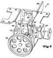
- FIG. 1 to 8 of the drawing is a lifting device 10 for a preferred embodiment shown.
- the lifting device 10 is connectable to a lawn tractor 12 Mower designed.
- the lawn tractor 12 can be seen in FIG. 1 and is provided with a frame 14 which the mower housing 16 of the mower can be connected.
- the mower housing 16 is located below the frame 14 between the two steerable front wheels 18 and the two drivable Rear wheels 20.
- the vehicle 12 is with a drive source or an internal combustion engine 22 equipped to drive the rear wheels 20, or the knife of the mower housing 16 and other components or devices has an output shaft.
- the high disk 24 consists of a central shaft 26 and two face plates connected to it in a rotationally fixed manner and having a vertical spacing from one another or pulleys 28 and 30.
- a drive belt 32 is guided around the first pulley 28, which extends rearward to the vehicle transmission, not shown, and ultimately to drive the serves two rear wheels 20.
- a belt 34 is guided around the second and lower pulley 30, which is used to drive the mower blades of the mower housing, which is why on the mower housing 16 corresponding pulleys 36 are provided.
- the mower can either be lifted or lifted be lowered.
- the lifting device is initially equipped with a friction wheel 38 is provided between the upper and lower pulleys 28 and 30 and from its in Fig. 3rd
- the neutral position shown is adjustable into a position according to FIG. 6 or 7, so that a friction gear with change of direction arises.
- a rotatable output part is rotatably connected, which is designed in the preferred embodiment as a threaded rod 40. And so that the friction wheel 38 can be pivoted between its positions, the threaded rod 40 rotatably mounted in a pivotable support bracket 42.
- the support bracket 42 is in a support bracket 46 is pivotable, which can be U-shaped and then with his Leg ends are screwed to the vehicle frame.
- the support bracket 42 is then one horizontally arranged pin 44 between the legs of the support bracket 46 vertically pivoted stored.
- the support bracket 42 is adjusted from the driver's cab, which is why the support bracket 42 is also adjusted a rearward-facing control arm 49 is firmly connected, for example, to which a control lever 48 leading to the operating or driver's station 50 is articulated. This in turn engages with its other end on one provided in the driver's cab and in the vehicle frame 14 mounted hand lever 52 so that when the hand lever is adjusted by the operator the mower is raised. If the hand lever is adjusted downwards, it will Mower lowered.
- a sliding part 54 On the threaded rod 40 is a sliding part 54 provided with an internal thread adjustable when the threaded rod turns.
- the sliding part 54 is also laterally protruding projections or sections 55 which adjust the connecting rod for height adjust the mower when the part 54 moves on the spindle 40.
- a U-shaped lever 56 the legs of which at their lower End abut against the projections 54 and with their upper ends on a transverse shaft 58 rotatably sit on, which in turn is mounted in the legs of the support beam 46.
- Sitting on the cross shaft 58 also a boom 60 rotatably on, the other end via a linkage 62 on the Mower housing 16 attacks. If the lever 56 is now moved forward or backward, then the mower housing is moved up or down.
- the linkage 62 engages the rear part of the mower housing, the front portion 64 on a support bracket 66 is suspended, which is pivotally connected to the vehicle.
- the support bracket thus carries the front section of the mower housing, even if it is
- the preferred embodiment is also with a cutting height adjustment device 68 fitted.
- This is actuated via an adjustment button 70, which can be seen in FIGS. 1 and 2 the driver's cab 50 is provided and is seated on a shaft 72 which extends through the floor 74 of the Driver's cab extends into this.
- the other end of the shaft 72 is on a step wheel 76 (see 2 and 4) connected, the individual stages are designated 78.
- Steps 78 which are assigned to the individual adjustable cutting heights, arrive Height adjustment lever 80, which is connected to the boom 60 via a strut 82, for contact and determines the cutting height.
- the height adjustment lever 80 is on the lifting linkage 62 connected and pivoted about its junction in the form of a shaft 84 if that Mower housing is raised or lowered.
- the operator moves the hand lever 52 upwards, whereby the adjusting lever 48 is adjusted downwards.
- the support bracket 42 and the control arm 49 from the position shown in FIG. 3 clockwise and the friction wheel 38 upwards until it comes into contact with a friction disk 89, which in the preferred embodiment has a has a larger diameter than the upper pulley 28, but can be directly below this and circulates with it.
- the friction disk 89 rotates, the friction wheel 38 and its spindle rotate 40 in the direction of arrow A in FIG. 6 and the sliding part 54 moves in the direction of arrow B in 6, that is to the front and towards the friction wheel 38.
- the lever 56, the cross shaft 58 and the boom 60 pivoted clockwise from their positions in Fig. 3.
- the strut 82 is pulled from its position in Fig. 2 to the left or to the front, causing height adjustment lever 80, turn shaft 84 and the booms counterclockwise.
- the hanger 88 and so the mower housing 16 are pulled up or adjusted.
- the friction wheel In the position shown in FIG. 3, the friction wheel has neither the friction disk 89 nor the lower one Pulley 30 contact. The friction wheel 38 then cannot rotate and the mower housing 16 cannot be adjusted in height. This position is called the neutral position.
- the preferred exemplary embodiment is also provided with a device 92 which causes the control arm 49 and the support bracket 42 in their neutral position, in which the friction wheel is not in contact with the friction disc 89 or with the lower pulley 30 has to be returned when the Operator releases the hand lever 52.
- the return is made by a metallic leaf spring 94 which is connected to the frame 14 and to the control arm 49.
- the first cam surface 96 thus prevents a further downward movement of the Mower because the friction wheel 38 loses contact with the lower pulley 30 and into it Neutral position returns.
- the sliding part come to rest against a second cam surface 98 which on the left or front end of the support beam 46 is provided.
- This cam surface 98 causes the sliding part 54 moves downward, as a result of which the friction wheel 38 makes its contact with the friction disk 89 loses and returns to its neutral position.
- the reset device is always activated when the mower approaches its highest or lowest position.
- the cutting height adjuster 68 of the preferred embodiment is best seen in FIGS 2 and 4 can be seen.
- the operator can easily set the desired cutting height by turning the knob 70.
- the mower is then lowered again by operating the hand lever 52.
- the mower lowers due to its own weight until that the height adjustment lever 80 against a step 78 of the step wheel 76 comes to rest.
- Each step corresponds to a certain cutting height, and that In this way, the operator can select the cutting height after lifting the mower easy to find again.
- an elongated hole 100 is provided, which ensures the function of the cam surface 96 when a Cutting height adjustment device 68 is provided. It has already been pointed out that at a lowering of the mower housing 16 to a predetermined cutting height of the height adjustment lever 80 comes against the step wheel 76 to the system. In such a case, the height adjustment lever 80, shaft 84 and cantilevers 86 no longer clockwise with reference to FIG. 2 swivel and the mower is blocked against further lowering. On the other hand, the friction wheel 38 is then still driven by the lower pulley 30, so that the sliding part 54 continues to move backwards.
- the sliding part 54 will turn out normally Adjust on the spindle 40 until it comes into contact with the first cam surface 96. At a contact of the sliding part with the first cam surface, the sliding part will be down adjust while swiveling the support bracket 42 with the friction wheel into the neutral position according to FIG. 3 reset.
- the lost motion connection allows the operator to have a Preselect or adjust the cutting height and then regardless of the cutting height Hand lever 52 can hold for any length in the position for lowering because of the lifting device automatically returns to neutral. Without such a function, the operator would have to Release the hand lever when the desired cutting height is reached.
- the lifting device 10 described above is thus ultimately from the internal combustion engine 22 of the Vehicle driven and can be easily operated by an operator without they have large or larger muscle forces to raise or lower the mower, which in several Knives has a considerable weight, should be used. Of course, there are also no hydraulic cylinders or complex linkage devices required, making the lifting device significant would become more expensive.
- the basic concept of the present invention can also be used in a friction gear to drive a device or the drive wheels of a vehicle.
- the threaded spindle could be raised or lowered as a driven part 40 be connected to a drive shaft which drives the wheels of a manually operated lawn mower, a snow blower or a sweeper.
- the simple pivoting of the Friction wheels between its upper and lower positions would then rotate in one direction for forward travel and result in a direction of rotation for reverse travel.
- the center position of the friction wheel would correspond to a neutral position.
- the friction wheel gear naturally does not have to have any pulleys. Friction disks would suffice, which should then be dimensioned accordingly.
- the friction disc 89 is provided because of the outer diameter the upper pulley is relatively small.
Landscapes
- Engineering & Computer Science (AREA)
- General Engineering & Computer Science (AREA)
- Mechanical Engineering (AREA)
- Harvester Elements (AREA)
Claims (12)
- Dispositif d'entraínement à roue de friction comportant un arbre (26) pouvant être entraíné à partir d'une source de force, un premier disque de friction (89) relié de manière à être bloqué en rotation à l'arbre (26), et une roue de friction (38) comportant une partie menée, et dans lequel un second disque de friction est prévu à distance du premier disque de friction sur l'arbre (26) pouvant être entraíné et dans lequel la roue de friction (38) peut basculer entre trois positions de telle sorte que dans la première position, la roue de friction (38) s'applique contre le premier disque de friction (89) et peut être entraínée dans un premier sens de rotation, que dans la seconde position, la roue de friction (38) s'applique contre le second disque de friction et peut être entraínée dans un second sens de rotation opposé au premier sens de rotation, et que dans la troisième position, la roue de friction (38) est distante des premier et second disques de friction et ne peut pas être entraínée, caractérisé en ce qu'au moins un disque de friction est agencé sous la forme d'une poulie (30).
- Dispositif d'entraínement à roue de friction comportant une roue de friction (38) pouvant être entraínée à partir d'une source de force, et un premier disque de friction. (89) relié avec blocage en rotation à une partie menée, et dans lequel un second disque de friction est prévu sur la partie menée à distance du premier disque de friction (89), et dans lequel la roue de friction (38) peut pivoter entre trois positions respectivement la partie menée est réglable, de telle sorte que dans la première position, le premier disque de friction (89) s'applique contre la roue de friction (38) et peut être entraíné dans un premier sens de rotation, que dans la seconde position, le second disque de friction s'applique contre la roue de friction (38) et peut être entraíné dans un second sens de rotation opposé au premier sens de rotation, et que dans la troisième position, les premier et second disques de friction sont situés à distance de la roue de friction (38) et ne peuvent pas être entraínés, caractérisé en ce qu'au moins un disque de friction est agencé sous la forme d'une poulie (30).
- Dispositif d'entraínement à roue de friction selon la revendication 1 ou la revendication 2, caractérisé en ce qu'on utilise comme source de force, un moteur à combustion interne (22) prévu sur un véhicule (12).
- Dispositif d'entraínement à roue de friction selon une ou plusieurs des revendication précédentes, caractérisé en ce que sa partie menée est raccordée à un dispositif de levage (10) servant à soulever et abaisser un appareil en fonction du sens de rotation du dispositif d'entraínement de la roue de friction.
- Dispositif d'entraínement à roue de friction selon la revendication 4, caractérisé en ce que l'arbre pouvant être entraíné (26) sert à entraíner les roues motrices (20) d'un véhicule (12) et à entraíner les outils de l'appareil, l'appareil étant raccordé au véhicule (12) de manière à être réglable en hauteur.
- Dispositif d'entraínement à roue de friction selon la revendication 5, caractérisé en ce que les roues motrices (20) et/ou les outils de l'appareil peuvent être reliés à la poulie par l'intermédiaire d'une courroie.
- Dispositif d'entraínement à roue de friction avec changement de direction selon une ou plusieurs des revendications précédentes, caractérisé en ce que la partie menée coopère avec une partie coulissante (54), qui convertit le mouvement de rotation de la partie menée en un mouvement de translation qui s'étend dans la direction de l'axe longitudinal de la partie menée et, lors de son mouvement, actionne une tringlerie de levage au moins pour soulever l'appareil.
- Dispositif d'entraínement à roue de friction selon la revendication 7, caractérisé en ce que la partie menée est agencée sous la forme d'une tige filetée (40), qui est reliée à la roue de friction (38) et que la partie coulissante (54) est guidée sans possibilité de rotation sur le filetage de la tige filetée (40), la tige filetée (40) étant montée de manière à pouvoir pivoter conjointement avec la roue de friction (38), et la partie coulissante (54) coopère avec un levier pivotant (56), qui est relié à la tringlerie de levage.
- Dispositif d'entraínement à roue de friction selon la revendication 8, caractérisé en ce que la tige filetée (40) et le levier pivotant (56) sont montés de manière à pouvoir pivoter verticalement dans un support (46) stationnaire, qui possède au moins une surface de came (96 ou 98) servant à ramener automatiquement la roue de friction (38) dans sa position neutre.
- Dispositif d'entraínement à roue de friction selon une ou plusieurs des revendications précédentes, caractérisé en ce qu'il est utilisé pour le réglage en hauteur d'une unité de coupe raccordée à un tracteur-tondeuse, l'arbre pouvant être entraíné (26) du dispositif d'entraínement à roue de friction servant à entraíner au moins le couteau ou les couteaux de l'unité de coupe, et la roue de friction (38) pouvant être actionnée manuellement à partir du siège (50) du conducteur.
- Dispositif d'entraínement à roue de friction selon une ou plusieurs des revendications 4 à 10, caractérisé en ce que le dispositif de levage (10) peut coopérer avec un dispositif de réglage en hauteur (68).
- Dispositif d'entraínement à roue de friction selon la revendication 11, caractérisé en ce que le dispositif de réglage en hauteur (68) comporte une roue étagée (76), qui peut coopérer avec un levier de réglage en hauteur (80), qui coopère avec l'appareil respectivement le dispositif de levage (10), de telle sorte que le levier de réglage en hauteur (80) peut s'appliquer sur des étages pouvant être prédéterminés (78) de la roue étagée.
Applications Claiming Priority (2)
| Application Number | Priority Date | Filing Date | Title |
|---|---|---|---|
| US08/621,278 US5784870A (en) | 1996-03-22 | 1996-03-22 | Power lift mechanism for mower deck |
| US621278 | 1996-03-22 |
Publications (3)
| Publication Number | Publication Date |
|---|---|
| EP0797026A2 EP0797026A2 (fr) | 1997-09-24 |
| EP0797026A3 EP0797026A3 (fr) | 1998-07-08 |
| EP0797026B1 true EP0797026B1 (fr) | 2001-05-30 |
Family
ID=24489513
Family Applications (1)
| Application Number | Title | Priority Date | Filing Date |
|---|---|---|---|
| EP97104664A Expired - Lifetime EP0797026B1 (fr) | 1996-03-22 | 1997-03-19 | Entraínement par friction de roues |
Country Status (5)
| Country | Link |
|---|---|
| US (1) | US5784870A (fr) |
| EP (1) | EP0797026B1 (fr) |
| AU (1) | AU696010B2 (fr) |
| CA (1) | CA2194595C (fr) |
| DE (1) | DE59703632D1 (fr) |
Families Citing this family (23)
| Publication number | Priority date | Publication date | Assignee | Title |
|---|---|---|---|---|
| US5927055A (en) * | 1997-07-16 | 1999-07-27 | Deere & Company | Pivoting mower deck mechanism |
| JP3474103B2 (ja) * | 1998-05-26 | 2003-12-08 | 株式会社クボタ | 芝刈機のモーア吊設装置 |
| US6434919B2 (en) * | 1998-11-13 | 2002-08-20 | Shivvers Group Incorporated | Raiseable mower deck |
| US6988351B2 (en) | 1998-11-13 | 2006-01-24 | Shivvers Group, Inc. | Midmount mower apparatus with raiseable and accessible mower deck |
| US6293077B1 (en) | 2000-05-02 | 2001-09-25 | Mtd Products Inc | Deck attachment and lift system |
| US6837032B1 (en) * | 2000-08-15 | 2005-01-04 | Deere & Company | Pedal actuated height adjustment mechanism for a mower cutting deck |
| IT251364Y1 (it) * | 2000-11-13 | 2003-11-19 | Rotomec Spa | Falciaerba con sistema migliorato dei piatti falcianti |
| US6651529B1 (en) | 2002-07-02 | 2003-11-25 | Hydro-Gear Limited Partnership | Hydrostatic transmission |
| US7028456B2 (en) * | 2003-07-14 | 2006-04-18 | Shivvers Group, Inc. | Mower with flip up mowing deck |
| US7596936B2 (en) * | 2003-07-14 | 2009-10-06 | Shivvers Group, Inc. | Mower deck placed in maintenance and varying height positions |
| US7540134B1 (en) | 2003-07-17 | 2009-06-02 | Pat Reich | Riding mower with deck height adjustment |
| US7013626B1 (en) | 2003-07-18 | 2006-03-21 | Auburn Consolidated Industries, Inc. | Walk behind mower |
| US7540135B2 (en) * | 2005-07-13 | 2009-06-02 | Claude Strope | Mower deck height adjustment |
| US7730705B2 (en) * | 2007-04-20 | 2010-06-08 | Parker-Hannifin Corporation | Electro-hydraulic lift mechanism for lawn mower deck |
| JP4934511B2 (ja) * | 2007-06-05 | 2012-05-16 | 株式会社クボタ | 作業車の作業装置下降規制構造 |
| WO2012166123A1 (fr) * | 2011-05-31 | 2012-12-06 | Husqvarna Consumer Outdoor Products N.A., Inc. | Véhicule léger autoporté à entraînement par friction variable |
| US20130074464A1 (en) | 2011-09-22 | 2013-03-28 | Ariens Company | Integrated transaxles for standing lawn mower |
| US9693501B2 (en) | 2014-08-06 | 2017-07-04 | Shivvers Group Incorporated | Mower with scissor lift mowing height adjustment mechanism |
| US9861035B2 (en) | 2015-05-01 | 2018-01-09 | Deere & Company | Height of cut control system |
| US9481244B1 (en) | 2015-06-09 | 2016-11-01 | Ariens Company | Friction drive system for a utility machine |
| US11006574B1 (en) * | 2017-02-14 | 2021-05-18 | Alamo Group Inc. | Mower with rotary cut height adjustment |
| US11310961B2 (en) * | 2019-04-18 | 2022-04-26 | Deere & Company | Mower deck transport lock |
| US12010944B2 (en) * | 2020-09-21 | 2024-06-18 | Deere & Company | Mower deck transport lock |
Family Cites Families (19)
| Publication number | Priority date | Publication date | Assignee | Title |
|---|---|---|---|---|
| US751878A (en) * | 1904-02-09 | Territory | ||
| US807176A (en) * | 1905-05-29 | 1905-12-12 | Marion Steam Shovel Co | Raising and lowering mechanism. |
| US1530053A (en) * | 1923-01-11 | 1925-03-17 | Mueller Hilmar | Ceramic press and the like |
| DE517030C (de) * | 1927-07-10 | 1931-01-30 | Eduard Meyer Maschf | Wendegetriebe |
| US2622689A (en) * | 1949-05-19 | 1952-12-23 | Frank G Szager | Power lawn mower |
| US2711624A (en) * | 1954-07-02 | 1955-06-28 | Owen D Crump | Mowing attachment for a tractor |
| US3396519A (en) * | 1965-10-23 | 1968-08-13 | Aircapital Manufacturers Inc | Height adjustment mechanism for power mower vehicles |
| US3481213A (en) * | 1967-09-11 | 1969-12-02 | Salvatore La Macchia | Quick traverse machine tool accessory apparatus |
| US3813954A (en) * | 1970-12-28 | 1974-06-04 | Gilson Brothers Co | Friction drive with axially spaced disks and intermediate shiftable wheel |
| US3720112A (en) * | 1971-10-22 | 1973-03-13 | Gilson Brothers Co | Load limiter for self-energizing drive |
| US3795094A (en) * | 1972-10-30 | 1974-03-05 | Ariens Co | Riding mower |
| US4271378A (en) * | 1978-12-28 | 1981-06-02 | Knauff Robert J | Toy with reversible driven hoist |
| US4318266A (en) * | 1980-12-15 | 1982-03-09 | Max Taube | Remotely controlled self-propelled power lawn mower |
| AU573971B2 (en) * | 1985-04-01 | 1988-06-23 | Linson-Smith, L. | Reversible transmission |
| US4663923A (en) * | 1985-11-05 | 1987-05-12 | Ferris Industries, Inc. | Self-propelled mower |
| US5042239A (en) * | 1990-04-06 | 1991-08-27 | Scag Power Equipment, Inc. | Power transmission and steering apparatus for vehicles |
| US5065568A (en) * | 1990-07-26 | 1991-11-19 | Deere & Company | Mower deck height adjustment mechanism |
| US5353578A (en) * | 1993-03-02 | 1994-10-11 | Fuqua Industries, Inc. | Drive system for lawn mowers |
| US5390479A (en) * | 1993-06-22 | 1995-02-21 | Deere & Company | Implement drive structure |
-
1996
- 1996-03-22 US US08/621,278 patent/US5784870A/en not_active Expired - Lifetime
-
1997
- 1997-01-07 CA CA002194595A patent/CA2194595C/fr not_active Expired - Fee Related
- 1997-02-13 AU AU12685/97A patent/AU696010B2/en not_active Ceased
- 1997-03-19 DE DE59703632T patent/DE59703632D1/de not_active Expired - Fee Related
- 1997-03-19 EP EP97104664A patent/EP0797026B1/fr not_active Expired - Lifetime
Also Published As
| Publication number | Publication date |
|---|---|
| AU1268597A (en) | 1997-10-23 |
| EP0797026A3 (fr) | 1998-07-08 |
| EP0797026A2 (fr) | 1997-09-24 |
| CA2194595A1 (fr) | 1997-09-23 |
| DE59703632D1 (de) | 2001-07-05 |
| CA2194595C (fr) | 1999-12-14 |
| US5784870A (en) | 1998-07-28 |
| AU696010B2 (en) | 1998-08-27 |
Similar Documents
| Publication | Publication Date | Title |
|---|---|---|
| EP0797026B1 (fr) | Entraínement par friction de roues | |
| EP0448992B1 (fr) | Mécanisme de sécurité pour un outil de travail, en particulier une tondeuse à gazon | |
| EP0445623B1 (fr) | Transmission à courroie pour un instrument de travail, en particulier pour une tondeuse à gazon connectée à un véhicule | |
| EP0475021B1 (fr) | Tondeuse, en particulier tondeuse frontale | |
| DE3784509T2 (de) | Rasenmaehvorrichtung. | |
| AT508217B1 (de) | Bodenbearbeitungsvorrichtung | |
| DE1932229B2 (de) | Heuwerbungsmaschine | |
| EP0933016B1 (fr) | Dispositif de support et véhicule pour l'entretien du terrain | |
| DE9112551U1 (de) | Vorrichtung zum Entfernen von Bodenbelägen | |
| DE2652823A1 (de) | Bremsgelenktes fahrzeug, insbesondere zugmaschine, mit lenkhebel und einer hilfssteuerung mit selbstzentriervorrichtung | |
| DE2121962A1 (de) | Im Gehen zu betätigender Hubkarren | |
| DE19534695C2 (de) | An einem Schlepper ansetzbares Heckmähwerk | |
| DE69911173T2 (de) | Wendekontrollsystem für rasentraktor | |
| DE9112331U1 (de) | Mähmaschine | |
| DE69403511T2 (de) | Heuwerbungsmaschine | |
| DE19622452A1 (de) | Mähvorrichtung | |
| DE60025218T2 (de) | Fahrerhaus für Erdbewegungsmaschinen | |
| DE69504081T2 (de) | Schlepper-aufgehangene mähmaschine | |
| DE2407514C3 (de) | Tellerbesenanordnung an Kehrmaschinen | |
| DE19516634C1 (de) | Vorrichtung zur Höhenverstellung eines Rades eines Fahrgestells, insbesondere von einem Rasenmäher | |
| DE4105287A1 (de) | Vorrichtung fuer fahrzeuge und maschinen | |
| DE3411161A1 (de) | Bodenbearbeitungsmaschine, insbesondere kreiselegge | |
| DE1430138C3 (de) | Steuereinrichtung für ein hydrostatisches Getriebe eines mit einer Anhängevorrichtung bzw. einem Geräteanschluß ausgerüsteten Schleppers | |
| EP0181947B1 (fr) | Roue porteuse oscillante pour charrues-brabant | |
| DE29600075U1 (de) | Pflug |
Legal Events
| Date | Code | Title | Description |
|---|---|---|---|
| PUAI | Public reference made under article 153(3) epc to a published international application that has entered the european phase |
Free format text: ORIGINAL CODE: 0009012 |
|
| AK | Designated contracting states |
Kind code of ref document: A2 Designated state(s): DE FR GB IT SE |
|
| PUAL | Search report despatched |
Free format text: ORIGINAL CODE: 0009013 |
|
| AK | Designated contracting states |
Kind code of ref document: A3 Designated state(s): DE FR GB IT SE |
|
| 17P | Request for examination filed |
Effective date: 19980813 |
|
| 17Q | First examination report despatched |
Effective date: 20000215 |
|
| GRAG | Despatch of communication of intention to grant |
Free format text: ORIGINAL CODE: EPIDOS AGRA |
|
| GRAG | Despatch of communication of intention to grant |
Free format text: ORIGINAL CODE: EPIDOS AGRA |
|
| GRAH | Despatch of communication of intention to grant a patent |
Free format text: ORIGINAL CODE: EPIDOS IGRA |
|
| RAP1 | Party data changed (applicant data changed or rights of an application transferred) |
Owner name: DEERE & COMPANY |
|
| GRAH | Despatch of communication of intention to grant a patent |
Free format text: ORIGINAL CODE: EPIDOS IGRA |
|
| GRAA | (expected) grant |
Free format text: ORIGINAL CODE: 0009210 |
|
| AK | Designated contracting states |
Kind code of ref document: B1 Designated state(s): DE FR GB IT SE |
|
| REF | Corresponds to: |
Ref document number: 59703632 Country of ref document: DE Date of ref document: 20010705 |
|
| ITF | It: translation for a ep patent filed | ||
| GBT | Gb: translation of ep patent filed (gb section 77(6)(a)/1977) |
Effective date: 20010810 |
|
| ET | Fr: translation filed | ||
| REG | Reference to a national code |
Ref country code: GB Ref legal event code: IF02 |
|
| PLBE | No opposition filed within time limit |
Free format text: ORIGINAL CODE: 0009261 |
|
| STAA | Information on the status of an ep patent application or granted ep patent |
Free format text: STATUS: NO OPPOSITION FILED WITHIN TIME LIMIT |
|
| 26N | No opposition filed | ||
| PGFP | Annual fee paid to national office [announced via postgrant information from national office to epo] |
Ref country code: SE Payment date: 20060329 Year of fee payment: 10 |
|
| PG25 | Lapsed in a contracting state [announced via postgrant information from national office to epo] |
Ref country code: SE Free format text: LAPSE BECAUSE OF NON-PAYMENT OF DUE FEES Effective date: 20070320 |
|
| EUG | Se: european patent has lapsed | ||
| PGFP | Annual fee paid to national office [announced via postgrant information from national office to epo] |
Ref country code: IT Payment date: 20070521 Year of fee payment: 11 |
|
| PGFP | Annual fee paid to national office [announced via postgrant information from national office to epo] |
Ref country code: FR Payment date: 20080317 Year of fee payment: 12 Ref country code: DE Payment date: 20080219 Year of fee payment: 12 |
|
| PG25 | Lapsed in a contracting state [announced via postgrant information from national office to epo] |
Ref country code: IT Free format text: LAPSE BECAUSE OF NON-PAYMENT OF DUE FEES Effective date: 20080319 |
|
| REG | Reference to a national code |
Ref country code: FR Ref legal event code: ST Effective date: 20091130 |
|
| PG25 | Lapsed in a contracting state [announced via postgrant information from national office to epo] |
Ref country code: DE Free format text: LAPSE BECAUSE OF NON-PAYMENT OF DUE FEES Effective date: 20091001 |
|
| PG25 | Lapsed in a contracting state [announced via postgrant information from national office to epo] |
Ref country code: FR Free format text: LAPSE BECAUSE OF NON-PAYMENT OF DUE FEES Effective date: 20091123 |
|
| PGFP | Annual fee paid to national office [announced via postgrant information from national office to epo] |
Ref country code: GB Payment date: 20140327 Year of fee payment: 18 |
|
| GBPC | Gb: european patent ceased through non-payment of renewal fee |
Effective date: 20150319 |
|
| PG25 | Lapsed in a contracting state [announced via postgrant information from national office to epo] |
Ref country code: GB Free format text: LAPSE BECAUSE OF NON-PAYMENT OF DUE FEES Effective date: 20150319 |