EP0795620B1 - Verfahren zum Beschichten von Wellzylindern mittels sauerstoffthermischen Brennstoffspritzens hoher Geschwindigkeit - Google Patents
Verfahren zum Beschichten von Wellzylindern mittels sauerstoffthermischen Brennstoffspritzens hoher Geschwindigkeit Download PDFInfo
- Publication number
- EP0795620B1 EP0795620B1 EP96301751A EP96301751A EP0795620B1 EP 0795620 B1 EP0795620 B1 EP 0795620B1 EP 96301751 A EP96301751 A EP 96301751A EP 96301751 A EP96301751 A EP 96301751A EP 0795620 B1 EP0795620 B1 EP 0795620B1
- Authority
- EP
- European Patent Office
- Prior art keywords
- gun
- roll
- coating
- longitudinal axis
- spray
- Prior art date
- Legal status (The legal status is an assumption and is not a legal conclusion. Google has not performed a legal analysis and makes no representation as to the accuracy of the status listed.)
- Expired - Lifetime
Links
- 238000000576 coating method Methods 0.000 title claims description 55
- 239000011248 coating agent Substances 0.000 title claims description 47
- 238000000034 method Methods 0.000 title claims description 31
- 239000007921 spray Substances 0.000 title claims description 22
- QVGXLLKOCUKJST-UHFFFAOYSA-N atomic oxygen Chemical compound [O] QVGXLLKOCUKJST-UHFFFAOYSA-N 0.000 title claims description 11
- 239000001301 oxygen Substances 0.000 title claims description 11
- 229910052760 oxygen Inorganic materials 0.000 title claims description 11
- 239000000463 material Substances 0.000 claims description 16
- 229910017052 cobalt Inorganic materials 0.000 claims description 11
- 239000010941 cobalt Substances 0.000 claims description 11
- WFKWXMTUELFFGS-UHFFFAOYSA-N tungsten Chemical compound [W] WFKWXMTUELFFGS-UHFFFAOYSA-N 0.000 claims description 10
- 229910052721 tungsten Inorganic materials 0.000 claims description 10
- 239000010937 tungsten Substances 0.000 claims description 10
- 238000005507 spraying Methods 0.000 claims description 5
- 239000007789 gas Substances 0.000 claims description 4
- 238000000227 grinding Methods 0.000 description 15
- PXHVJJICTQNCMI-UHFFFAOYSA-N Nickel Chemical compound [Ni] PXHVJJICTQNCMI-UHFFFAOYSA-N 0.000 description 8
- 229910003460 diamond Inorganic materials 0.000 description 8
- 239000010432 diamond Substances 0.000 description 8
- 239000000843 powder Substances 0.000 description 5
- 229910052750 molybdenum Inorganic materials 0.000 description 4
- 229910052759 nickel Inorganic materials 0.000 description 4
- 238000007747 plating Methods 0.000 description 4
- VYZAMTAEIAYCRO-UHFFFAOYSA-N Chromium Chemical compound [Cr] VYZAMTAEIAYCRO-UHFFFAOYSA-N 0.000 description 3
- 239000011230 binding agent Substances 0.000 description 3
- 239000000446 fuel Substances 0.000 description 3
- 238000004519 manufacturing process Methods 0.000 description 3
- UONOETXJSWQNOL-UHFFFAOYSA-N tungsten carbide Chemical compound [W+]#[C-] UONOETXJSWQNOL-UHFFFAOYSA-N 0.000 description 3
- XLYOFNOQVPJJNP-UHFFFAOYSA-N water Substances O XLYOFNOQVPJJNP-UHFFFAOYSA-N 0.000 description 3
- UFHFLCQGNIYNRP-UHFFFAOYSA-N Hydrogen Chemical compound [H][H] UFHFLCQGNIYNRP-UHFFFAOYSA-N 0.000 description 2
- ZOKXTWBITQBERF-UHFFFAOYSA-N Molybdenum Chemical compound [Mo] ZOKXTWBITQBERF-UHFFFAOYSA-N 0.000 description 2
- 229910018487 Ni—Cr Inorganic materials 0.000 description 2
- ATUOYWHBWRKTHZ-UHFFFAOYSA-N Propane Chemical compound CCC ATUOYWHBWRKTHZ-UHFFFAOYSA-N 0.000 description 2
- 229910052804 chromium Inorganic materials 0.000 description 2
- 239000011651 chromium Substances 0.000 description 2
- UFGZSIPAQKLCGR-UHFFFAOYSA-N chromium carbide Chemical compound [Cr]#C[Cr]C#[Cr] UFGZSIPAQKLCGR-UHFFFAOYSA-N 0.000 description 2
- VNNRSPGTAMTISX-UHFFFAOYSA-N chromium nickel Chemical compound [Cr].[Ni] VNNRSPGTAMTISX-UHFFFAOYSA-N 0.000 description 2
- GUTLYIVDDKVIGB-UHFFFAOYSA-N cobalt atom Chemical compound [Co] GUTLYIVDDKVIGB-UHFFFAOYSA-N 0.000 description 2
- 239000000498 cooling water Substances 0.000 description 2
- 238000010438 heat treatment Methods 0.000 description 2
- 239000001257 hydrogen Substances 0.000 description 2
- 229910052739 hydrogen Inorganic materials 0.000 description 2
- 239000003350 kerosene Substances 0.000 description 2
- 150000001247 metal acetylides Chemical class 0.000 description 2
- 239000011733 molybdenum Substances 0.000 description 2
- 239000000123 paper Substances 0.000 description 2
- 239000011087 paperboard Substances 0.000 description 2
- 229910052710 silicon Inorganic materials 0.000 description 2
- HBMJWWWQQXIZIP-UHFFFAOYSA-N silicon carbide Chemical compound [Si+]#[C-] HBMJWWWQQXIZIP-UHFFFAOYSA-N 0.000 description 2
- 229910010271 silicon carbide Inorganic materials 0.000 description 2
- 229910003470 tongbaite Inorganic materials 0.000 description 2
- MTPVUVINMAGMJL-UHFFFAOYSA-N trimethyl(1,1,2,2,2-pentafluoroethyl)silane Chemical compound C[Si](C)(C)C(F)(F)C(F)(F)F MTPVUVINMAGMJL-UHFFFAOYSA-N 0.000 description 2
- 229910052580 B4C Inorganic materials 0.000 description 1
- 241000220010 Rhode Species 0.000 description 1
- 229910000831 Steel Inorganic materials 0.000 description 1
- HSFWRNGVRCDJHI-UHFFFAOYSA-N alpha-acetylene Natural products C#C HSFWRNGVRCDJHI-UHFFFAOYSA-N 0.000 description 1
- PNEYBMLMFCGWSK-UHFFFAOYSA-N aluminium oxide Inorganic materials [O-2].[O-2].[O-2].[Al+3].[Al+3] PNEYBMLMFCGWSK-UHFFFAOYSA-N 0.000 description 1
- 230000015572 biosynthetic process Effects 0.000 description 1
- 238000005422 blasting Methods 0.000 description 1
- INAHAJYZKVIDIZ-UHFFFAOYSA-N boron carbide Chemical compound B12B3B4C32B41 INAHAJYZKVIDIZ-UHFFFAOYSA-N 0.000 description 1
- OJIJEKBXJYRIBZ-UHFFFAOYSA-N cadmium nickel Chemical compound [Ni].[Cd] OJIJEKBXJYRIBZ-UHFFFAOYSA-N 0.000 description 1
- 238000002485 combustion reaction Methods 0.000 description 1
- 150000001875 compounds Chemical class 0.000 description 1
- 238000001816 cooling Methods 0.000 description 1
- 229910052593 corundum Inorganic materials 0.000 description 1
- 238000005336 cracking Methods 0.000 description 1
- 238000005520 cutting process Methods 0.000 description 1
- 230000008021 deposition Effects 0.000 description 1
- 238000009826 distribution Methods 0.000 description 1
- 238000005516 engineering process Methods 0.000 description 1
- 230000003628 erosive effect Effects 0.000 description 1
- 125000002534 ethynyl group Chemical group [H]C#C* 0.000 description 1
- -1 for example kerosene Chemical class 0.000 description 1
- 229930195733 hydrocarbon Natural products 0.000 description 1
- 150000002430 hydrocarbons Chemical class 0.000 description 1
- 238000007373 indentation Methods 0.000 description 1
- 229910052500 inorganic mineral Inorganic materials 0.000 description 1
- 239000007788 liquid Substances 0.000 description 1
- 238000002844 melting Methods 0.000 description 1
- 230000008018 melting Effects 0.000 description 1
- 239000011707 mineral Substances 0.000 description 1
- 239000000203 mixture Substances 0.000 description 1
- TWNQGVIAIRXVLR-UHFFFAOYSA-N oxo(oxoalumanyloxy)alumane Chemical compound O=[Al]O[Al]=O TWNQGVIAIRXVLR-UHFFFAOYSA-N 0.000 description 1
- 239000002245 particle Substances 0.000 description 1
- 239000001294 propane Substances 0.000 description 1
- QQONPFPTGQHPMA-UHFFFAOYSA-N propylene Natural products CC=C QQONPFPTGQHPMA-UHFFFAOYSA-N 0.000 description 1
- 125000004805 propylene group Chemical group [H]C([H])([H])C([H])([*:1])C([H])([H])[*:2] 0.000 description 1
- 239000010959 steel Substances 0.000 description 1
- 239000000758 substrate Substances 0.000 description 1
- 238000005496 tempering Methods 0.000 description 1
- 229910001845 yogo sapphire Inorganic materials 0.000 description 1
Images


Classifications
-
- C—CHEMISTRY; METALLURGY
- C23—COATING METALLIC MATERIAL; COATING MATERIAL WITH METALLIC MATERIAL; CHEMICAL SURFACE TREATMENT; DIFFUSION TREATMENT OF METALLIC MATERIAL; COATING BY VACUUM EVAPORATION, BY SPUTTERING, BY ION IMPLANTATION OR BY CHEMICAL VAPOUR DEPOSITION, IN GENERAL; INHIBITING CORROSION OF METALLIC MATERIAL OR INCRUSTATION IN GENERAL
- C23C—COATING METALLIC MATERIAL; COATING MATERIAL WITH METALLIC MATERIAL; SURFACE TREATMENT OF METALLIC MATERIAL BY DIFFUSION INTO THE SURFACE, BY CHEMICAL CONVERSION OR SUBSTITUTION; COATING BY VACUUM EVAPORATION, BY SPUTTERING, BY ION IMPLANTATION OR BY CHEMICAL VAPOUR DEPOSITION, IN GENERAL
- C23C4/00—Coating by spraying the coating material in the molten state, e.g. by flame, plasma or electric discharge
- C23C4/12—Coating by spraying the coating material in the molten state, e.g. by flame, plasma or electric discharge characterised by the method of spraying
- C23C4/14—Coating by spraying the coating material in the molten state, e.g. by flame, plasma or electric discharge characterised by the method of spraying for coating elongate material
-
- C—CHEMISTRY; METALLURGY
- C23—COATING METALLIC MATERIAL; COATING MATERIAL WITH METALLIC MATERIAL; CHEMICAL SURFACE TREATMENT; DIFFUSION TREATMENT OF METALLIC MATERIAL; COATING BY VACUUM EVAPORATION, BY SPUTTERING, BY ION IMPLANTATION OR BY CHEMICAL VAPOUR DEPOSITION, IN GENERAL; INHIBITING CORROSION OF METALLIC MATERIAL OR INCRUSTATION IN GENERAL
- C23C—COATING METALLIC MATERIAL; COATING MATERIAL WITH METALLIC MATERIAL; SURFACE TREATMENT OF METALLIC MATERIAL BY DIFFUSION INTO THE SURFACE, BY CHEMICAL CONVERSION OR SUBSTITUTION; COATING BY VACUUM EVAPORATION, BY SPUTTERING, BY ION IMPLANTATION OR BY CHEMICAL VAPOUR DEPOSITION, IN GENERAL
- C23C4/00—Coating by spraying the coating material in the molten state, e.g. by flame, plasma or electric discharge
- C23C4/12—Coating by spraying the coating material in the molten state, e.g. by flame, plasma or electric discharge characterised by the method of spraying
Definitions
- the present invention relates to fluted rolls and, more particularly, to a method of coating fluted rolls, such as corrugating rolls, whereby the rolls are provided with a hardened outer surface for resisting wear.
- Corrugating rolls are used in machinery such as single facer or double facer corrugators which are used in the manufacture of corrugated paperboard.
- the corrugating rolls include a series of flutes formed around the circumference of the roll, wherein the flutes are adapted to form corrugations in a paper web during the formation of corrugated paperboard.
- the rolls were rough machined using ordinary cutting tools and then hardened by conventional heat treatment. The heat treatment tended to distort the machined roll such that a further operation of grinding was required to obtain the final desired dimensions for the flutes on the roll.
- a hard exterior coating was typically applied to the surface of the roll to thereby increase its resistance to wear.
- chrome plating has been used to coat the outer surface of corrugating rolls, and such chrome plating has provided the desired result of increasing the life of the roll.
- problems associated with the use of chrome plating on rolls including the plating being susceptible to cracking and chipping. Once the surface of the roll has cracks or chips, the wear caused by the sliding of the paper web over the roll greatly increases, such that the useful life of the roll before it is either replaced or reground is significantly shortened.
- the present invention is directed to a method of coating a roll defining a longitudinal axis and having an undulated surface including longitudinal extending flutes defined by alternating tips and gullets with flanks extending between the tips and gullets, generally of the type disclosed in Patent Abstracts of Japan, Vol.12, No.
- method comprises the steps of aligning a high velocity gas fueled gun with the undulated surface, spraying a coating material onto the surface from the gun to form a hardened coating, and rotating the roll while causing relative movement between the gun and the roll in a direction parallel to the longitudinal axis, the step of aligning the gun comprising changing the orientation of the gun relative to the roll such that a centerline for an outlet of the gun is fixed in different positions disposed non-diametrically of the roll.
- the outlet or nozzle of the spray gun is located with its centerline nearly perpendicular to the flanks of the flutes on the roll, and, during spraying from the different orientations, the roll is rotated in the same direction.
- the present invention provides an improved method for forming a hardened coating on a roll having an undulated surface, such as on a fluted corrugating roll.
- the spray gun is a high velocity oxygen fueled gun
- the step of aligning the gun comprises:
- the hardened coating is formed of a tungsten carbide-cobalt material.
- other coating materials may be used, including coatings of chromium carbide, titanium carbide, silicon carbide and tribaloy (Co, Mo, Cr, Si) with binders such as nickel, nickel cadmium, molybdenum and the like.
- the step of aligning the gun includes directing the outlet or nozzle of the gun to spray along a line extending transverse to a line extending from the gun outlet diametrically through the roll.
- the spray of coating material is not directed along a diametrical line for the roll, but rather is directed at an angle in such a manner that only a portion of the flutes are sprayed at any given time.
- the gun is located above a center line for the corrugating roll and is traversed along the length of the corrugating roll while the roll is rotated about its axis in a first direction. Subsequently, the gun is moved to a position below the center line for the roll and is traversed across the length of the roll while the roll is rotated in a second direction opposite to the first direction.
- the particular location of the gun above and below the center line for the roll is selected such that the desired uniform surface characteristics are produced on the surface of the roll.
- the coated dimensions of the flutes are substantially close to the desired tolerances for the finished roll.
- the finished surface for the roll may be provided by a honing operation without an intermediate grinding operation.
- an apparatus for performing the above-described steps for coating the roll.
- the apparatus includes a mount for holding the roll, a high velocity oxygen fueled gun and control means for moving the gun relative to the roll whereby the orientation and location of the gun relative to the roll is altered.
- the control means includes a first driver for moving the gun in a direction parallel to the longitudinal axis of the roll, and further includes a second driver for moving the gun in a direction perpendicular to a plane passing through the longitudinal axis of the roll.
- means are provided for rotating the roll while the roll is located on the mount.
- An advantage of the present invention is that it enables the forming of a hardened coating having substantially uniform surface characteristics on a corrugating roll,using a high velocity oxygen fueled gun.
- the present invention is directed toward providing a workpiece having discontinuous or undulated surface with a hardened coating formed of a tungsten carbide-cobalt material. Further, it should be noted that although the present invention is described with reference to providing such a coating to a corrugating roll, this invention is intended to encompass other applications, such as applying a coating to gear teeth, splines or other workpieces having undulated surfaces.
- corrugating rolls with a tungsten carbide-cobalt surface coating or other hard coating materials including chromium carbide, titanium carbide, boron carbide, silicon carbide, aluminum oxide and tribaloy (Co, Mo, Cr, Si) with binder materials such as cobalt, nickel, nickel chromium, molybdenum and the like.
- tungsten carbide-cobalt surface coating or other hard coating materials including chromium carbide, titanium carbide, boron carbide, silicon carbide, aluminum oxide and tribaloy (Co, Mo, Cr, Si) with binder materials such as cobalt, nickel, nickel chromium, molybdenum and the like.
- carbide coatings have been used for several different applications in order to provide extended life for tooling, the application of such a coating to fluted corrugating rolls, as well as other discontinuous or undulating surfaces, has proven to be difficult.
- carbide coatings typically form a rough non-uniform outer surface in their as-deposited condition on the corrugating roll flutes, and the thickness of the coating normally tends to be significantly greater in the gullet of the flute, as compared to the thickness at the flute tip.
- the inherent hardness of such carbide coatings makes them resistant to grinding with conventional grinding tools.
- grinding operations performed on tungsten carbide or other carbides and oxides typically involve using diamond either as a grinding wheel or as a diamond lapping compound.
- the diamond grinding wheel In the case of grinding fluted corrugating rolls, the diamond grinding wheel must be provided with a shape which conforms to the shape of the flutes forming the roll.
- the diamond grinding wheel loses its shape and dimensional control such that a diamond grinding wheel for all practical purposes is not capable of providing the desired dimensional tolerances for the flutes.
- it is not possible to dress a diamond wheel such that diamond wheels configured to grind the fluted areas cannot be reused once they lose their dimensional tolerances.
- a corrugating roll coated with tungsten carbide must be substantially within the desired tolerances at the end of the coating operation or the finishing operation for the roll may become prohibitively expensive.
- a method has been developed for applying a tungsten carbide-cobalt material (or other hard carbides or oxides with binders of nickel, nickel chromium, nickel Cr Mo, etc.) to the roll wherein the coating has substantially uniform surface characteristics such that minimal surface irregularities are present.
- the present invention provides a coating which is sufficiently uniform to ensure that any variations in the thickness of the coating between the gullets and tips of the flutes are maintained within a desired tolerance whereby the finished surface of the roll may be produced through a honing operation without requiring an intermediate grinding operation.
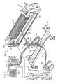
- the apparatus 10 includes a roll mount 12 having opposing first and second end supports 14, 16.
- the end supports 14, 16 include respective support shafts 18, 20 for supporting the opposing ends of a fluted corrugating roll 22.
- the apparatus 10 further includes a spray gun support 24 for supporting a high velocity oxygen fueled (HVOF) gun 26.
- the HVOF gun 26 essentially uses an internal combustion jet to produce hypersonic gas velocities for spraying the tungsten carbide-cobalt which is fed in powder form into the jet. For example, a mixture of 88wt% tungsten carbide to 12wt% cobalt is satisfactory for use in the present method.
- the jet may be fueled by various gaseous and liquid hydrocarbons such as for example kerosene, napthaleen, propylene, acetylene, propane, map gas or hydrogen and others in combination with oxygen. In the preferred embodiment, either hydrogen or kerosene is used.
- the gun 26 may be any one of several high velocity oxygen fueled guns which are commercially available such as, for example, a JP 5000 gun sold by Hobart Tafa Technologies Inc. of Concord, New Hampshire.
- the gun 26 is supported on a vertical mounting bar 28 and the vertical mounting bar 28 is supported on a first driver 30 which is adapted to traverse the spray gun 26 along the roll 22 in a horizontal direction X parallel to a longitudinal axis 32 of the roll 22.
- the mounting bar 28 includes a second driver 29 for driving the spray gun 26 in a vertical direction Y along the bar 28.
- the roll 22 is preferably driven for rotational movement by a further driver, such as a motor, located within one of the end supports 14, 16.
- the means for moving the gun 26 relative to the roll 22 may be a commercially available apparatus, such as a BUG-O unit sold by Weld Tooling Corp. of Pittsburgh, Pennsylvania.
- the BUG-O unit includes a guide track incorporating a screw thread, rotation of the screw thread causing precisely controlled horizontal movement of a device, such as the gun 26, along the track. It should also be noted that vertical movement of the gun 26 may be controlled by conventional means such as a rotatable screw thread mounted in the bar 28, or other known means for providing vertical translational movement.
- the gun 26 is supplied with tungsten carbide-cobalt powder or other carbide or oxide powders from a powder feeder 34 through a flexible hose 36 connected to the gun 26.
- the powder feeder 34 is controlled by a powder feeder control console 38.
- an oxygen/fuel/cooling water control console 40 is provided for supplying oxygen and fuel from supply tanks 42 to the gun 26, and for supplying cooling water from a water treatment and cooling station 44 to a water cooled nozzle 46 defining an outlet for the gun 26.
- the oxygen, fuel and water are supplied to the gun 26 through flexible supply lines 48.
- a central programmable controller 50 is connected to each of the control consoles 38 and 40 and is further connected to the drives for moving the gun 26 and for rotating the corrugating roll 22.
- the controller 50 coordinates the different operations including the movement of the gun 26 and the roll 22 and actuation of the gun 26 to spray the tungsten carbide-cobalt material onto the roll 22 in accordance with the method of the present invention, as will be described further below.
- a typical coating operation in accordance with the present invention is performed by aligning the gun 26 such that a center line 52 of the nozzle 46 extends parallel to a plane 54 extending diametrically through the corrugating roll 22 and passing through the longitudinal axis 32 wherein the plane 54 is substantially horizontal.
- the gun 26 is located on the mounting bar 28 at a vertical position which is a predetermined distance L above the plane 54.
- FIG. 3 an enlarged view of flutes 70, 72, 74, 76 is shown wherein the flutes 70, 72, 74 and 76 include respective flute tips 78, 80, 82 and 84.
- Flanks 70a, 70b, 72a, 72b, 74a, 74b, 76a, 76b extend from the flute tips 78, 80, 82, 84 down to gullets 71, 73, 75, respectively.
- the diameter D of the spray 62 is such that it will generally cover a flute tip half 80b, a flank 72b, a gullet 73 and another flute tip half 82a. In other words, the spray diameter D is sufficient to span a full flute tip width, a flank and a gullet.
- the position of the gun 26 is selected such that the spray 62 propelled from the gun 26 has a trajectory substantially parallel to adjoining flanks 72a and 74a while impinging substantially directly on the flank 72b, tip halves 80b and 82a, and gullet 73. Thus, only a portion of each flute is selectively coated with the gun 26 positioned above the plane 54.
- flute 76 is illustrated as having passed through the spray 62 such that substantially the entire flute tip 84 has been coated whereas the flute tip half 80a and flute 70 have not been coated since this portion of the roll has not passed through the spray 62 in its rotation in the direction A.
- the driver 30 is activated to traverse the gun 26 along the length of the roll 22. Simultaneously, the driver within either of the end supports 14, 16 causes the roll 22 to rotate a plurality of times in the direction A, as shown in Fig. 2.
- the gun 26 is moved to the position shown by the gun 26' in Fig. 2. As shown, the gun 26' is located a distance L below the horizontal plane 54 whereby the flank portion 74a, located on the opposing side of the gullet 73 from the flank 72b, will be coated. During this portion of the coating operation the gun 26 will be traversed along the length of the roll 22 while the roll 22 is rotated in a second direction B opposite to the first direction A. Thus, during coating of the roll, the roll 22 will be rotated such that surfaces being coated by the spray will move in a direction toward the spray.
- the honing process may be performed using a bar-shaped honing tool 86, such as is illustrated in Figs. 4 and 5.
- the honing tool 86 is preferably formed with a steel base 88 including a shaped honing portion 90.
- the honing portion 90 is provided with a gullet-shaped indentation 92 which is configured to hone a flute including the flute tip, both flanks and one-half the adjacent gullets.
- the honing portion 90 includes a diamond surface coating 94 forming the working surface of the honing tool.
- the honing tool may be mounted in a conventional honer which is commercially available, such as the Supfina SE40 sold by Supfina Machine Co., Inc. of Warwick, Rhode Island, which vibrates the honing tool 86 as it is moved along the length of the flutes for the corrugating roll.
- a conventional honer which is commercially available, such as the Supfina SE40 sold by Supfina Machine Co., Inc. of Warwick, Rhode Island, which vibrates the honing tool 86 as it is moved along the length of the flutes for the corrugating roll.
- the present honing tool 86 smoothes the coated surface to produce the final flute dimensions required for the finished corrugating roll.
- this process for coating a roll provides a desired coating thickness at each portion of the flute such that subsequent grinding is not required.
- the honing operation may be performed immediately after the coating operation in order to provide the finished surface for the corrugating roll 22 without performing an intermediate grinding operation.
- the position of the gun 26 relative to the plane 54 may be held constant for multiple traversing passes along the length of the roll prior to moving the gun 26 to the position illustrated by gun 26'.
- control of the angle at which the spray 62 impinges upon the roll 22 may be accomplished by angling the gun 26 upwardly or downwardly relative to the plane 54 in addition to or instead of moving the gun vertically.
- HVOF tungsten carbide-cobalt coating process provides a desirable process for coating the rolls wherein the maximum temperature of the roll is limited.
- the present process provides the roll with a carbide coating while maintaining the temperature of the roll below 149°C (300°F) such that tempering (resulting in softening of the substrate) or distortion of the flutes from either warpage of the roll or melting of the flutes is avoided.
- the roll prior to coating a roll in accordance with the process of the present invention, the roll is grit blasted to attain a uniformly roughened surface finish whereby mechanical adhesion of the coating to the roll surface is promoted. It is important that the blasting be performed uniformly to the tips, flanks and gullets, and the process may be performed using Al 2 O 3 grit or other hard mineral particles.
- the present invention provides a method for coating workpieces having a discontinuous or undulating surface, for example, the present coating method may be applied to corrugating rolls, gears, ratchets and similar workpieces.
Landscapes
- Chemical & Material Sciences (AREA)
- Engineering & Computer Science (AREA)
- Physics & Mathematics (AREA)
- Plasma & Fusion (AREA)
- Chemical Kinetics & Catalysis (AREA)
- Materials Engineering (AREA)
- Mechanical Engineering (AREA)
- Metallurgy (AREA)
- Organic Chemistry (AREA)
- Coating By Spraying Or Casting (AREA)
Claims (9)
- Verfahren zur Beschichtung einer Walze (22) mit einer Längsachse (32) und mit einer gewellten Oberfläche mit sich längs erstreckenden Auskehlungen (70, 72, 74, 76), die durch alternierende Firste (78, 80, 82, 84) und Hohlkehlen (71, 73, 75) mit Flanken (70a, 70b, 72a, 72b, 74a, 74b, 76a, 76b), welche sich zwischen den Firsten und Hohlkehlen erstrecken, begrenzt sind, mit den Stufen, in denen man:dadurch gekennzeichnet, daß die Pistole (26) eine mit Sauerstoff hoher Geschwindigkeit befeuerte Pistole ist und daß die Stufe der Ausrichtung der Pistole einschließt, daß man:eine mit Gas hoher Geschwindigkeit gefeuerte Pistole (26) mit der gewählten Oberfläche ausrichtet,ein Beschichtungsmaterial auf die Oberfläche aus der Pistole (26) unter Bildung eines gehärteten Überzuges aufspritzt,die Walze (22) rotieren läßt, während man eine Relativbewegung zwischen der Pistole (26) und der Walze (22) in einer Richtung parallel zu der Längsachse (32) bewirkt,wobei die Stufe der Ausrichtung der Pistole eine Veränderung der Orientierung der Pistole (26) in Bezug auf die Walze (22) umfaßt, so daß eine Mittellinie (52) für einen Auslaß (46) der Pistole in unterschiedlichen, nicht diametral zu der Walze angeordneten Positionen fixiert wird,um dabei eine gehärtete Beschichtung auf der Walzenoberfläche mit im wesentlichen gleichmäßigen Oberflächeneigenschaften zu bilden.a) die Pistole (26) in Bezug auf die Walze (22) derart orientiert, daß die Mittellinie (52) für den Auslaß (46) der Pistole in einer Position fixiert wird, die parallel zu einer der Flanken (80a) wenigstens einer der Auskehlungen (72) ausgerichtet ist,b) die Walze in einer ersten Richtung (A) rotieren läßt, während man eine Relativbewegung zwischen der Pistole und der Walze in einer Richtung (X) parallel zu der Längsachse (32) bewirkt,c) die Orientierung der Pistole derart verändert, daß die Mittellinie (52') für den Auslaß (46) zu der Pistole in einer Position fixiert wird, die parallel zu der anderen Flanke (80b) der wenigstens einen Auskehlung (72) ausgerichtet ist, undd) die Walze in einer zweiten Richtung (B) entgegengesetzt zu der ersten Richtung (A) rotieren läßt, während man eine Relativbewegung zwischen der Pistole und der Walze in einer Richtung parallel zu der Längsachse bewirkt,
- Verfahren nach Anspruch 1, bei dem die Stufen b) und d) eine Rotation der Walze in einer ersten und einer zweiten Richtung derart umfassen, daß die Oberflächen, die durch den Sprühstrahl (62) beschichtet werden, sich zu dem Sprühstrahl hin bewegen.
- Verfahren nach Anspruch 1 oder 2, bei dem die Stufe der Ausrichtung der Pistole umfaßt, daß man den Auslaß (46) für die Pistole so anordnet, daß die Mittellinie (52) im Abstand (L) zu einer Seite einer Ebene (54) liegt, die diametral durch die Walze (22) und durch die Längsachse (32) geht, und die Pistole so ausrichtet, daß sie parallel zu der Ebene (54) sprüht, und anschließend den Auslaß für die Pistole mit seiner Mittellinie im Abstand (L) zu einer gegenüberliegenden Seite der Ebene (54) bewegt.
- Verfahren nach Anspruch loder 2, bei dem die Stufe einer Ausrichtung der Pistole umfaßt, daß man die Pistole anwinkelt, so daß die Mittellinie an entgegengesetzten Seiten einer Ebene divergiert, die diametral durch die Walze und durch die Längsachse geht.
- Verfahren nach einem der vorausgehenden Ansprüche, bei dem der Durchmesser (D) des Sprühstrahles (62) ausreicht, um eine Auskehlungsfirsthälfte (80b), eine Flanke (72b), eine Hohlkehle (73) und eine andere Auskehlungsfirsthälfte (82a) zu beschichten.
- Verfahren nach einem der vorausgehenden Ansprüche, bei dem die Pistole (26) mehrmals über die Walze (22) traversiert und die Walze mehrmals während einer Überquerung der Pistole rotiert.
- Verfahren nach einem der vorausgehenden Ansprüche, bei dem das Beschichtungsmaterial ein Wolframcarbid-Cobalt-Material ist.
- Verfahren nach einem der vorausgehenden Ansprüche mit der Stufe, in der man den Überzug schleift.
- Verfahren nach einem der vorausgehenden Ansprüche, bei dem die Walze (22) eine Rillenwalze ist.
Priority Applications (3)
| Application Number | Priority Date | Filing Date | Title |
|---|---|---|---|
| DE69613555T DE69613555T2 (de) | 1996-03-14 | 1996-03-14 | Verfahren zum Beschichten von Wellzylindern mittels sauerstoffthermischen Brennstoffspritzens hoher Geschwindigkeit |
| ES96301751T ES2158244T3 (es) | 1996-03-14 | 1996-03-14 | Metodo de revestir cilindros estriados mediante el empleo de un chorro termico alimentado con oxigeno de alta velocidad. |
| EP96301751A EP0795620B1 (de) | 1996-03-14 | 1996-03-14 | Verfahren zum Beschichten von Wellzylindern mittels sauerstoffthermischen Brennstoffspritzens hoher Geschwindigkeit |
Applications Claiming Priority (1)
| Application Number | Priority Date | Filing Date | Title |
|---|---|---|---|
| EP96301751A EP0795620B1 (de) | 1996-03-14 | 1996-03-14 | Verfahren zum Beschichten von Wellzylindern mittels sauerstoffthermischen Brennstoffspritzens hoher Geschwindigkeit |
Publications (2)
| Publication Number | Publication Date |
|---|---|
| EP0795620A1 EP0795620A1 (de) | 1997-09-17 |
| EP0795620B1 true EP0795620B1 (de) | 2001-06-27 |
Family
ID=8224852
Family Applications (1)
| Application Number | Title | Priority Date | Filing Date |
|---|---|---|---|
| EP96301751A Expired - Lifetime EP0795620B1 (de) | 1996-03-14 | 1996-03-14 | Verfahren zum Beschichten von Wellzylindern mittels sauerstoffthermischen Brennstoffspritzens hoher Geschwindigkeit |
Country Status (3)
| Country | Link |
|---|---|
| EP (1) | EP0795620B1 (de) |
| DE (1) | DE69613555T2 (de) |
| ES (1) | ES2158244T3 (de) |
Families Citing this family (5)
| Publication number | Priority date | Publication date | Assignee | Title |
|---|---|---|---|---|
| ES2133077B1 (es) * | 1996-10-08 | 2000-04-01 | Espan Carburos Metal | Procedimiento para la obtencion de conformados por proyeccion termica. |
| RU2135630C1 (ru) * | 1998-02-12 | 1999-08-27 | Военный автомобильный институт | Способ плазменного напыления |
| GB9803561D0 (en) * | 1998-02-19 | 1998-04-15 | Monitor Coatings & Eng | Surface treatment of rotors |
| EP1816229B1 (de) * | 2006-01-31 | 2010-03-24 | Siemens Aktiengesellschaft | Thermisches Spritzverfahren und Vorrichtung zum Durchführen des Verfahrens |
| CN107639526A (zh) * | 2016-07-22 | 2018-01-30 | 上海大松瓦楞辊有限公司 | 一种用于瓦楞辊的碳化钨喷涂和表面抛光装置 |
Family Cites Families (5)
| Publication number | Priority date | Publication date | Assignee | Title |
|---|---|---|---|---|
| DE2028050A1 (de) * | 1970-06-08 | 1971-12-16 | Metallgesellschaft Ag | Verfahren zur Herstellung korrosions- und verschleißfester metallischer Überzüge durch Aufspritzen |
| JPS619565A (ja) * | 1984-06-22 | 1986-01-17 | Tanaka Kikinzoku Kogyo Kk | 金属複合材の製造方法 |
| JPS62204875A (ja) * | 1986-03-03 | 1987-09-09 | Nippon Alum Mfg Co Ltd:The | 吹付け装置 |
| JPH0726188B2 (ja) * | 1986-03-31 | 1995-03-22 | 三菱重工業株式会社 | シングルフエ−サ用段ロ−ル及びその製造方法 |
| DE59003344D1 (de) * | 1989-11-16 | 1993-12-09 | Mannesmann Ag | Verfahren und Vorrichtung zum Aufbringen eines metallischen Überzuges auf die Gewindeabschnitte miteinander kraftverschraubbarer Kunststoffrohre. |
-
1996
- 1996-03-14 DE DE69613555T patent/DE69613555T2/de not_active Expired - Fee Related
- 1996-03-14 ES ES96301751T patent/ES2158244T3/es not_active Expired - Lifetime
- 1996-03-14 EP EP96301751A patent/EP0795620B1/de not_active Expired - Lifetime
Also Published As
| Publication number | Publication date |
|---|---|
| EP0795620A1 (de) | 1997-09-17 |
| ES2158244T3 (es) | 2001-09-01 |
| DE69613555D1 (de) | 2001-08-02 |
| DE69613555T2 (de) | 2002-04-25 |
Similar Documents
| Publication | Publication Date | Title |
|---|---|---|
| US5582874A (en) | Method for coating corrugating rolls using high velocity oxygen fueled thermal spray | |
| US7662020B2 (en) | Method for manufacturing surface-coated cutting insert | |
| US5622753A (en) | Method of preparing and coating aluminum bore surfaces | |
| US4600599A (en) | Method of applying a wear-resistant coating on a thin, metallic strip-shaped carrier material | |
| EP3666927B1 (de) | Zahnradprodukt mit verstärkter abscheidungsoberfläche und abscheidungssystem zur herstellung davon | |
| US5644828A (en) | Device for in situ repairing of a cylinder in a printing machine | |
| US4160048A (en) | Method of making a composite cast iron dryer or the like | |
| CA2455123C (en) | Coherent jet nozzles for grinding applications | |
| US8641479B2 (en) | Tool assembly for machining a bore | |
| CA1076784A (en) | Surfacing circular-section metal members | |
| EP1752230B1 (de) | Verfahren zum Reparieren eines Gasturbinenmotor Bauteils | |
| EP1058744B1 (de) | Oberflächenbehandlung von rotoren | |
| EP0795620A1 (de) | Verfahren zum Beschichten von Wellzylindern mittels einer sauerstoffthermischen Brennstoffspritzpistole von hoher Geschwindigkeit | |
| CN110142570A (zh) | 一种耐磨、抗粘钢复合涂层、制备方法及应用 | |
| CN109536868A (zh) | 石油输送分流环的内孔超音速火焰喷涂金属陶瓷涂层的方法 | |
| JPH09256135A (ja) | 高速酸素燃料熱スプレーを利用した波形ロールの製造方法 | |
| CN117778904B (zh) | 合金耐磨复合涂层及精轧辊超音速喷涂表面强化处理工艺 | |
| CN108842127B (zh) | 热轧辊超音速喷涂表面修复预处理方法 | |
| GB2150058A (en) | A method for the manufacture of a toothed tool for precision machining gear wheels | |
| RU2198240C2 (ru) | Способ плазменного напыления покрытий на внутреннюю цилиндрическую поверхность | |
| Fritz Klocke et al. | Honing | |
| RU2359803C1 (ru) | Способ внутреннего шлифования с продольной подачей | |
| JP2000198053A (ja) | タングステンカ―バイド表面の仕上げ | |
| KR970064741A (ko) | 고속의 산소 염료가 공급되는 열 분사를 파형 롤에 이용하는 방법 | |
| JPH09262915A (ja) | シングルフェーサ用段ロール及びその製造方法 |
Legal Events
| Date | Code | Title | Description |
|---|---|---|---|
| PUAI | Public reference made under article 153(3) epc to a published international application that has entered the european phase |
Free format text: ORIGINAL CODE: 0009012 |
|
| AK | Designated contracting states |
Kind code of ref document: A1 Designated state(s): DE ES FR GB IT |
|
| 17P | Request for examination filed |
Effective date: 19980227 |
|
| 17Q | First examination report despatched |
Effective date: 19990407 |
|
| GRAG | Despatch of communication of intention to grant |
Free format text: ORIGINAL CODE: EPIDOS AGRA |
|
| RTI1 | Title (correction) |
Free format text: METHOD FOR COATING FLUTED ROLLS USING HIGH VELOCITY OXYGEN FUELED THERMAL SPRAY |
|
| GRAG | Despatch of communication of intention to grant |
Free format text: ORIGINAL CODE: EPIDOS AGRA |
|
| GRAH | Despatch of communication of intention to grant a patent |
Free format text: ORIGINAL CODE: EPIDOS IGRA |
|
| GRAH | Despatch of communication of intention to grant a patent |
Free format text: ORIGINAL CODE: EPIDOS IGRA |
|
| GRAA | (expected) grant |
Free format text: ORIGINAL CODE: 0009210 |
|
| AK | Designated contracting states |
Kind code of ref document: B1 Designated state(s): DE ES FR GB IT |
|
| REF | Corresponds to: |
Ref document number: 69613555 Country of ref document: DE Date of ref document: 20010802 |
|
| REG | Reference to a national code |
Ref country code: ES Ref legal event code: FG2A Ref document number: 2158244 Country of ref document: ES Kind code of ref document: T3 |
|
| ITF | It: translation for a ep patent filed | ||
| ET | Fr: translation filed | ||
| REG | Reference to a national code |
Ref country code: GB Ref legal event code: IF02 |
|
| PG25 | Lapsed in a contracting state [announced via postgrant information from national office to epo] |
Ref country code: GB Free format text: LAPSE BECAUSE OF NON-PAYMENT OF DUE FEES Effective date: 20020314 |
|
| PG25 | Lapsed in a contracting state [announced via postgrant information from national office to epo] |
Ref country code: ES Free format text: LAPSE BECAUSE OF NON-PAYMENT OF DUE FEES Effective date: 20020315 |
|
| PLBE | No opposition filed within time limit |
Free format text: ORIGINAL CODE: 0009261 |
|
| STAA | Information on the status of an ep patent application or granted ep patent |
Free format text: STATUS: NO OPPOSITION FILED WITHIN TIME LIMIT |
|
| 26N | No opposition filed | ||
| GBPC | Gb: european patent ceased through non-payment of renewal fee |
Effective date: 20020314 |
|
| PG25 | Lapsed in a contracting state [announced via postgrant information from national office to epo] |
Ref country code: FR Free format text: LAPSE BECAUSE OF NON-PAYMENT OF DUE FEES Effective date: 20021129 |
|
| REG | Reference to a national code |
Ref country code: FR Ref legal event code: ST |
|
| PGFP | Annual fee paid to national office [announced via postgrant information from national office to epo] |
Ref country code: DE Payment date: 20040430 Year of fee payment: 9 |
|
| REG | Reference to a national code |
Ref country code: ES Ref legal event code: FD2A Effective date: 20030410 |
|
| PG25 | Lapsed in a contracting state [announced via postgrant information from national office to epo] |
Ref country code: IT Free format text: LAPSE BECAUSE OF NON-PAYMENT OF DUE FEES Effective date: 20050314 |
|
| PG25 | Lapsed in a contracting state [announced via postgrant information from national office to epo] |
Ref country code: DE Free format text: LAPSE BECAUSE OF NON-PAYMENT OF DUE FEES Effective date: 20051001 |