EP0795618B2 - Alliage à base de zirconium à faible croissance sous irradiation, procédé de fabrication et utilisation - Google Patents
Alliage à base de zirconium à faible croissance sous irradiation, procédé de fabrication et utilisation Download PDFInfo
- Publication number
- EP0795618B2 EP0795618B2 EP97301561A EP97301561A EP0795618B2 EP 0795618 B2 EP0795618 B2 EP 0795618B2 EP 97301561 A EP97301561 A EP 97301561A EP 97301561 A EP97301561 A EP 97301561A EP 0795618 B2 EP0795618 B2 EP 0795618B2
- Authority
- EP
- European Patent Office
- Prior art keywords
- heating
- channel box
- cooling
- value
- tubular member
- Prior art date
- Legal status (The legal status is an assumption and is not a legal conclusion. Google has not performed a legal analysis and makes no representation as to the accuracy of the status listed.)
- Expired - Lifetime
Links
Images


Classifications
-
- C—CHEMISTRY; METALLURGY
- C22—METALLURGY; FERROUS OR NON-FERROUS ALLOYS; TREATMENT OF ALLOYS OR NON-FERROUS METALS
- C22C—ALLOYS
- C22C16/00—Alloys based on zirconium
-
- C—CHEMISTRY; METALLURGY
- C22—METALLURGY; FERROUS OR NON-FERROUS ALLOYS; TREATMENT OF ALLOYS OR NON-FERROUS METALS
- C22F—CHANGING THE PHYSICAL STRUCTURE OF NON-FERROUS METALS AND NON-FERROUS ALLOYS
- C22F1/00—Changing the physical structure of non-ferrous metals or alloys by heat treatment or by hot or cold working
- C22F1/16—Changing the physical structure of non-ferrous metals or alloys by heat treatment or by hot or cold working of other metals or alloys based thereon
- C22F1/18—High-melting or refractory metals or alloys based thereon
- C22F1/186—High-melting or refractory metals or alloys based thereon of zirconium or alloys based thereon
-
- G—PHYSICS
- G21—NUCLEAR PHYSICS; NUCLEAR ENGINEERING
- G21C—NUCLEAR REACTORS
- G21C3/00—Reactor fuel elements and their assemblies; Selection of substances for use as reactor fuel elements
- G21C3/02—Fuel elements
- G21C3/04—Constructional details
- G21C3/06—Casings; Jackets
- G21C3/07—Casings; Jackets characterised by their material, e.g. alloys
-
- Y—GENERAL TAGGING OF NEW TECHNOLOGICAL DEVELOPMENTS; GENERAL TAGGING OF CROSS-SECTIONAL TECHNOLOGIES SPANNING OVER SEVERAL SECTIONS OF THE IPC; TECHNICAL SUBJECTS COVERED BY FORMER USPC CROSS-REFERENCE ART COLLECTIONS [XRACs] AND DIGESTS
- Y02—TECHNOLOGIES OR APPLICATIONS FOR MITIGATION OR ADAPTATION AGAINST CLIMATE CHANGE
- Y02E—REDUCTION OF GREENHOUSE GAS [GHG] EMISSIONS, RELATED TO ENERGY GENERATION, TRANSMISSION OR DISTRIBUTION
- Y02E30/00—Energy generation of nuclear origin
- Y02E30/30—Nuclear fission reactors
Definitions
- This invention relates to a method of manufacturing a fuel channel box.
- Zirconium alloy is a material having high corrosion resistance and a small neutron absorption cross section and is therefore used for a reactor fuel assembly member.
- Zr-Sn-Fe-Cr-Ni alloys called zircaloy-2 and zircaloy-4 are mainly used. If these alloys are used in a nuclear reactor for a long period of time, elongation and bow deformation In particular directions occur because (0001) planes thereof are oriented in the direction of plate thickness. If the bow deformation occurs in a fuel channel box, the space for driving the control rod is reduced, which impedes the operation of the reactor.
- the prior arts make crystal orientation of zirconium alloy member random.
- a channel box is quadrilateral and tubular, and, particularly, JP-A-5-17837 and JP-A-5-80170 disclose that, in order to make crystal orientation random, a heat treatment is performed by performing heating in ⁇ a temperature range followed by quenching, however, it is difficult to heat and to keep,the whole at uniform temperature. Consequently, if the whole member is not heated and kept at uniform temperature, there arises the difference in deformation by neutron irradiation, by which difference bow occurs.
- US-A-493891 discloses a process for producing a fuel element sheath from a zirconium-based alloy. A ⁇ temperature range heat treatment is used, but the degree of randomization this process produces is not disclosed.
- An object of the present invention is to provide a method of manufacturing a channel box, wherein deformation due to neutron irradiation growth is made more equal in amount at each position and bow deformation is avoided or minimized.
- the ⁇ 0001> crystal orientation of hexagonal Zr metal of the zirconium alloy plate of a large size is made highly random, and desirably the same random orientation is achieved at any position of the alloy plate.
- the method of the invention includes the step of: locally and continuously induction-heating the member in a ⁇ phase temperature range while being moved relatively and effecting a quenching treatment by forcibly cooling the heated portion of the member by use of cooling medium, the quenching treatment is performed plural times.
- a channel box produced according to the invention may be used so that the degree of burn-up on taking-out is not less than 32 GWd/t or so that nuclear fuel is exchanged at least two times during the use thereof, wherein an operation is preferably performed by locating the channel box for later operation in the same operation position as that of prior operation thereof.
- fuel is exchanged at least two times, and deformation occurring for such a period of time as the degree of bum-up on taking-out becomes 35 GWd/t or more or for such another period of time as neutron exposure becomes 10 22 n/cm 2 or more is decreased, and particularly an amount of bow per 4 m length of the channel box is not more than 2.16 mm.
- the channel box can be effectively used at a higher degree of burn-up of 38, 45, and 50 or not less than 50 GWd/t, so that advantage becomes remarkable.
- Deformation of zirconium alloy member occurs because the ⁇ 0001> direction of a hexagonal Zr is directed almost perpendicularly to the surface of the member.
- the hexagonal lattice is subjected to neutron irradiation, crystals contract in the ⁇ 0001> direction while expanding in the direction perpendicular to the ⁇ 0001> direction.
- a dislocation face perpendicular to the ⁇ 0001> direction is introduced by neutron irradiation to cause these contraction and expansion to the particular directions.
- the amount of neutron irradiation becomes greater in a position closer to the center of the reactor core, and it becomes smaller in the periphery of the reactor core.
- irradiation growth amount difference of elongation
- the L1 and L2 depend on the degree of bum-out, so that the amount of the bow is found to be dependent on Fl value and ⁇ F1 when the degree of bum-up is constant.
- the dependency of the amount of the bow of the channel box at 35 burn-up degree on Fl value and ⁇ Fl is calculated by the formula, so that the amount of the bow becomes minimum at the Fl range of 0.33 to 0.35 as shown in Fig. 6 and is reduced as ⁇ Fl is smaller.
- ⁇ must be less than 2.16 mm at 35 GWd/t burn-up degree.
- the blister amount increases due to creep during irradiation.
- a quenched member is deemed to have many sub-grain boundaries in each grain, and slippage along the grain boundaries is deemed to readily occur.
- the improvement can be achieved by decreasing the sub-grain boundaries by use of both annealing and recrystallization performed after cold rolling, whereby the amount of the bow of the channel box by irradiation growth is reduced and it becomes possible to obtain a channel box and a fuel assembly in both of which the leakage radiation dose is reduced.
- the deformation occurs because ⁇ 0001> crystal orientation of a hexagonal Zr metal is directed perpendicularly to the zirconium alloy surface.
- crystal contract in ⁇ 0001> direction while expanding in the direction perpendicular to the ⁇ 0001> direction.
- a dislocation face perpendicular to (0001) face is introduced by neutron irradiation to cause such contraction and expansion of the crystal. Consequently, in a fuel channel box in which ⁇ 0001 > crystal orientation is directed to be perpendicular to the surface, irradiation growth to the longitudinal and width directions occurs.
- An amount of neutron irradiation becomes greater in a position closer to the center of the reactor core, and there arises the difference in irradiation growth amount by the variation of neutron irradiation amount, causing the bow deformation.
- Randomly orientating ⁇ 0001> directions of crystals is effective in limiting the irradiation growth.
- the irradiation growth is a deformation without any change in volume, and even if each of the crystal grains of polycrystalline aggregate is deformed in a particular direction, all the directions of the deformation is random, which can be considered to be equivalent to no deformation as a whole.
- a method is ordinarily used in which an X-ray diffraction intensity of a particular crystal face is measured by use of a combination of reflected and transmission X-ray diffraction methods, and F value is calculated by equation (1) from the X-ray diffraction intensity measured: where ⁇ is an angle between a particular direction (e.g., a direction perpendicular to a plate surface) and a particular crystal orientation (e.g., ⁇ 0002> crystal orientation), and V( ⁇ ) is the volume proportion of crystals oriented in the direction ⁇ .
- ⁇ is an angle between a particular direction (e.g., a direction perpendicular to a plate surface) and a particular crystal orientation (e.g., ⁇ 0002> crystal orientation)
- V( ⁇ ) is the volume proportion of crystals oriented in the direction ⁇ .
- each of Fr, Ft and Fl is 0.20 to 0.50.
- Fr is 0.25 to 0.50
- Fl being 0.20 to 0.35
- Ft is 0.25 to 0.36.
- each of Fr, Ft and Fl is 0.31 to 0.35.
- the Fr value of (0002) crystal plane (equivalent to (0001) plane) of a plate and a tube manufactured by a process in which usual cold working and annealing are repeated is about 0.7, and (0001) crystal orientation is mainly directed in the direction normal to the plate (tube) surface.
- This state in which ⁇ 0001> crystal orientation is mainly oriented in the direction normal to the surface is called texture.
- the irradiation elongation is remarkably reduced when the Fl value is not less than 0.23 or preferably not less than 0.25.
- the elongation is limited to substantially 0 (zero) even in such a high irradiation range as the amount of neutron exposure ⁇ 10 22 (n/cm 2 ).
- ⁇ Zr crystal grains In order to obtain by this heat treatment atexture in which Fl value is 0.20 to 0.35, it is appropriate to grow ⁇ Zr crystal grains so that the grain size thereof is not less than 100 ⁇ m.
- ⁇ Zr crystal grains need to be grown to be at least not less than 50 ⁇ m but not more than 500 ⁇ m in grain size, and preferably not less than 150 ⁇ m but not more than 300 ⁇ m.
- the period of time for heating in the ⁇ phase temperature range may be shorter in a case where the heating temperature in ⁇ phase temperature range is higher (preferably 1,000 to 1,350°C, more preferably 1,000 to 1,200°C).
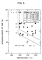
- the period of time for retention at the maximum temperature may be very short. For example, it is 1.5 to 100 sec., preferably 5 to 60 sec. It is particularly preferable to effect the heating in a range marked with the mark "•" in Fig. 5.
- Heating a whole member uniformly can be performed by the following means: a width of heating body is set to be not less than 3 cm, preferably not less than 4.5 cm, more preferably 4.5 to 10 cm (2 turns of high-frequency induction heating coil); the heating is performed while keeping the gap between the heated member and the heating body constant by use of rollers and quenching treatment is performed plural times; and the measurement of heated part is performed, etc.
- the gap is 1 to 5 mm, especially the gap of 2 to 3 mm is preferable.
- the Fr value varies according to the heat treatment, and the temperature and the retention time are important factors. Accordingly, in order to reduce the Fr value to be not more than 0.50 by heating in the ⁇ phase temperature range, it is preferable to set the parameter P obtained by the equation shown above to be not less than 1.5 ( ⁇ Zr crystal grain size of not less than 60 ⁇ m). Particularly, the parameter P is preferably 2.5 to 5 (a ⁇ Zr crystal grain size of 70 to 500 ⁇ m). More preferably, it is 3.2 to 5 (a ⁇ Zr crystal grain size of 100 to 500 ⁇ m).
- a suitable zirconium based alloy used as a cladding tube, a channel box and a spacer member contains not more than 5 wt% Sn and/or not more than 5 wt% Nb, and not less than 90 wt% (preferably 95 to 98.5 wt%) Zr.
- Sn and Nb are necessary to increase the strength of Zr. Not more than 5% of Sn and not more than 5% of Nb are required.
- the lower limit of each of Sn and Nb is 0.1%. In the zircaloy, 1 to 2% Sn is preferred, more preferably 1.2 to 1.7% Sn.
- This alloy may contain not more than 0.5% Fe and not more than 0.5% Cr, or may contain this amount of Cr and not more than 0.2% Ni, or these amounts of Fe and Ni. Particularly, it is preferred for the zircaloy to contain 0.05 to 0.20% Fe or 0.1 to 0.38% Fe, 0.05 to 0.15% Cr, or 0.03 to 0.10% Ni or 0.25% Ni added thereto, or to contain 0.22 to 0.38% Fe, 0.05 to 0.15% Cr and 0.09 to 0.15% Ni. In the latter case, Fe or Ni may be used alone, however, it is preferred to contain both of Fe and Ni. Preferable mixture ratio of (Fe/Ni) is 1.3 to 10.
- alloys containing Nb alloys of Zr - 0.5 to 2% Nb, Zr - 2 to 5% Sn - 0.5 to 1.5% Nb - 0.5 to 1.5% Mo, Zr - 0.5 to 0.15% Sn - 0.5 to 1.5% Nb - 0.1 to 1.0% Fe, Zr - 0.5 to 5.0% Nb - 0 to 3.0% Sn - not more than 2% of at least one selected from the group consisting of Fe, Ni, Cr, Ta, Pd, Mo and W are preferable.
- a tube member is successively heated for a desired retention time with an induction coil while moving the member so that the member is heated in the ⁇ phase temperature range, and the member is forcibly cooled after the heating.
- cooling is performed by spraying water (preferably spraying warm water), cooling speed being 50 to 300°C, preferably 100 to 250°C/sec.
- Other heating means such as infrared rays and an electric furnace, may be used.
- it is preferable to prevent deformation due to cooling by reducing the cooling speed for cooling by use of warm water of more than room temperature as a cooling medium for cooling.
- the temperature is preferably 40 to 80°C.
- the heated member When heating in the ⁇ phase temperature range, it is preferable to restrain the heated member by fixing it with a member having a thermal expansion coefficient larger than that of the Zr based alloy.
- a member having a thermal expansion coefficient larger than that of the Zr based alloy In particular, in the case of a tubular member, it is preferable to perform heating and cooling while inserting in the interior of the tube a metallic member contacted locally with the inner face of the member to be heated so as to reduce the thermal influence thereon by preventing the whole surfaces of these members from being in contact with each other and while fixing the opposite ends of these members so as to prevent the tubular member from deforming during the heating and cooling. In a case where the retaining member is provided, the heating and cooling can be performed easily.
- an austenitic stainless steel such as SUS304, 316, 347, etc. having a larger coefficient of thermal expansion than Zr based alloy is preferred.
- annealing for uniformly heating the whole of the member is performed.
- the annealing is effected at 500 to 650°C (preferably 550 to 640°C).
- the restraining member it is preferable to use the restraining member to restrain the heated member, whereby the tubular member can be suitably shaped.
- These heat treatments are effected in a non-oxidizing atmosphere, particularly the treatment in Ar being preferred.
- an oxidized layer on the surface is removed by sand blasting and pickling. After removing the oxidized layer, the surface is oxidized by an autoclave to form a stable oxidized coating thereon, thereby finishing the product. End portions of screw holes, etc. for fixing purpose at both of the ends are cut off for the use of the product.
- a channel box is formed by the steps of abutting two U-shaped members, plasma-welding the abutting portions to form an angular tube, and flattening the welded portion, and is thereafter used.
- this angular tube it is preferable to insert an X-shaped restraining member therein.
- an atomic power plant having a steam turbine actuated by thermal output obtained by atomic fuels contained in a reactor pressure vessel, and a generator is driven by the rotation of the turbine so as to generate an electric output, the thermal output of the reactor being not less than 3200MW, pressure in the reactor being not less than 7.0MPa, the temperature of the reactor being not less than 288°C, and an electric output being not less than 1100 MW, or alternatively the thermal output of the atomic reactor is not less than 4300MW, pressure in the reactor being not less than 7.2MPa, the temperature of the reactor being not less than 288°C, and an electric output being not less than 1500MW, to which power plant the fuel assembly is applied.
- Zircaloys used as zirconium alloy plate member having alloy compositions shown in Table 1 were used. They were heat-treated under the conditions shown in Table 2. Alloy name Alloy element Sn Nb Fe Cr Ni Mo O Zr Zircaloy-4 1.50 - 0.21 0.10 - 0.12 bal. Zircaloy-2 1.50 - 0.15 0.10 0.10 - 0.12 bal. Zircaloy-C 1.50 - 0.25 0.10 0.10 - 0.12 bal. Heat treatment No. Max. heating temperature (°C) Retention time (sec.) at Max.
- Each of the alloys was prepared as a plate having been formed to have a thickness of 2.5 mm by the repetition of both cold rolling and annealing performed at 650°C for two hours before being used.
- Heat treatment 2 to 4 shown in Table 2 were performed by the steps of heating the plate member having a width of 280 mm and a length of 4 m by means of a high-frequency induction coil, and cooling it with water circumferentially and uniformly by use of coil-like cooling nozzles wound thereunder in the same manner as the high-frequency induction coil.
- the parameter P was calculated by the above-mentioned equation.
- the upper and lower parts of the coil were fixed by rollers to prevent the plate from moving in right-and-left and back-and-forth directions so that the gap between the plate and the coil does not change.
- the coil has 3 turns, one turn having not less than 1 cm in heating width, so that the width of heating zone becomes not less than 4 cm, preferably 1.5 to 2 cm, which enabled the plate to have the uniformity of heating temperature.
- Warm water having the temperature of not less than 40°C was used for cooling, which prevented deformation from occurring during cooling and achieved uniform heating. No deformation of the plate member in this embodiment were found by visual inspection.
- Table 3 shows the results of F values measurement with respect to (0002) plane (parallel to (0001) plane) and (1010) plane (vertical to (0001) plane) of heat-treated members 1 to 6.
- the F values measurement was performed by the combination of the reflected/transmission X-ray diffraction methods mentioned above.
- Fr is orientation in a direction perpendicular to the surface thereof
- Fl being orientation in the longitudinal direction thereof
- Ft is orientation in the circumferential direction thereof.
- each of the F values of (0002) plane and (1010) plane is about 0.33, and it is understood that the crystal orientation is made substantially completely random. As described above, neither bow deformation nor elongation deformation is caused in the members processed by heat treatments 4 and 5, even if the non-uniformity of neutron exposure inside the member exists.
- Fig. 1 is a graph showing a relationship between fast neutron exposure and an amount of irradiation growth.
- the strain is abruptly increased as an amount of neutron exposure is increased in a case where the Fl value is not more than 0.3, but the strain is saturated and is not increased in another case where the Fl value exceeds 0.3.
- the strain is substantially naught, that is, is not more than 1 mm in the case of 4 m length and 60 GWd/t degree of bum-up.
- an amount of irradiation growth is as small as not more than 2 mm till 10 22 n/cm 2 neutron exposure, but the amount of irradiation growth is gradually increased in another case of Fl value larger than 0.3 as an amount of neutron exposure increases.
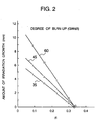
- Fig. 2 is a graph showing the relationship between the Fl value and an amount of irradiation growth caused by the irradiation corresponding to the degree of bum-up of 36.45 and 60 GWd/t.
- the amount of strain is increased abruptly.
- Roundish crystal grains observed in the metallic structure of each of the heat-treated member Nos. 1, 3 and 4 are ⁇ Zr grains. No ⁇ Zr crystal grains were observed. Also, the observed polygon-shaped crystal grains are ⁇ Zr crystal grains formed during the heating and keeping in the ⁇ phase temperature range. It is understood that, as the retention time at 1000°C is increased from 1 to 10 minutes, the grain size of ⁇ Zr crystal grows greatly. A layered or acicular structure found in the ⁇ Zr crystal grains is formed when the ⁇ Zr is again transformed into ⁇ Zr during cooling process, and is not ⁇ Zr grain boundary.
- Fig. 3 shows a relationship between the ⁇ Zr crystal grain size and the Fl value of (0002) plane. It is understood that a texture having the Fl value of not more than 0.33 is formed by the growth of ⁇ Zr crystal grains of not less than 200 ⁇ m.
- the degree of randomness of this orientation is about 75% when the Fl value is 0.30, at which case the grain size is about 100 ⁇ m.
- the degree of randomness is about not less than about 80%, and the Fl value becomes 0.310.
- the degree of randomness is about not less than about 90%, the grain size being about not less than 250 ⁇ m at this case.
- Fig. 4 is a graph showing the relationship between the ⁇ Zr crystal grain size and an amount of irradiation growth by fast neutron irradiation-corresponding to 60 GWd/t degree of burn-up. From Fig. 4, when the grain size is not less than 90 ⁇ m, the growth amount is zero which is remarkably small. When it is 10 ⁇ m, the growth amount is not more than 2 mm. Particularly, when it is not more than 35 ⁇ m, its growth amount becomes larger abruptly. An superior characteristic is obtained in a case where its growth amount is not more than 1 mm while the grain size is not less than 60 ⁇ m.
- the strain of irradiation growth is abruptly reduced when P exceeds 0.5, is gradually further reduced as P is changed from 0.5 to 3.5, and is approximately constant and close to zero when P is not less than 3.5.
- P is smaller than 3.5, irradiation growth occurs.
- P is 3.5 or greater, substantially no irradiation growth occurs.
- the effect of limiting the irradiation growth strain is sufficiently high when P is not less than 1.5.
- P is set to be 3.2 to 5.
- Fig. 5 is a graph showing a relation between the Fl value of alloys shown in Tables 1 and 4, each temperature and the retention time.
- the Fl value is not more than 0.20 and it is difficult to make ⁇ 0002> crystal orientation random.
- the heat-treated member can have an Fl value exceeding 0.25 and a higher degree of randomness.
- the heat-treated member can have an Fl value greater than 0.2 but not more than 0.25.
- the Fl value is not more than 0.20, the degree of randomness is small, and the effect of limiting the elongation is small.
- an actual channel box is a quadrilateral tubular body and has one side length of 140 mm, and particularly it is difficult to form it so that the F values at the opposed faces are the completely same.
- the above-mentioned irradiation growth strain is caused by the difference of F value, but what is the problem regarding the channel box is bow.
- the bow is caused particularly by the difference in F values of the opposed faces. The amount of the bow was measured by providing a very slight difference in F value between the opposed faces by changing the above-mentioned heat treatment condition.
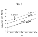
- Fig. 6 is a graph showing the F value (Fl) with respect to longitudinal direction of 4 m length and the amount of bow caused due to the difference of ⁇ Fl in the Fl value between the opposed faces.
- the amount of the bow is a value occurring at 35 GWd/t degree of burn-up, and a limiting value of 2.16 mm of the bow is shown as an tolerance value at the gap defined between a channel box and a control rod.
- ⁇ Fl value between the opposed faces corresponding to the bow of 2.16 mm which ⁇ Fl value is obtained regarding each of the Fl values, is increased as the degree of randomness of crystal orientation increases.
- ⁇ Fl it is preferred to obtain Fl by the steps of uniformly dividing the channel box face into a plurality of opposing sections, preferably 4 or more sections, and obtaining an average value of Fl regarding each of the opposing sections so that the difference in the average Fl values is measured.
- Fig. 7 is a graph showing a relationship between the Fl value and the difference in Fl value ( ⁇ Fl) between the opposed faces in the circumferential direction with respect to the threshhold value of the bow at the degree of bum-up of 35 GWd/t.
- Fig. 8 is a diagram showing a manufacturing process from a plate member to a final product.
- the plate member in this process uses the above-mentioned one, is heated by high-frequency induction coil and is cooled by use of a water-cooled nozzle provided at its lower position.
- the coil and a water-cooled nozzle are fixed, while the plate member is continuously moved upward.
- the measurement of heating temperature was performed at a space just before the water-cooled nozzle and just after the heating of the plate member directly by use of an optical pyrometer.
- a retention period of time of heating was controlled by adjusting a moving speed of the plate member.
- the temperature difference between the end and middle of the plate in the present embodiment was not more than 10°C, and several combination of heating temperature of 1050 to 1150°C and a retention period of time of 3 to 20 sec. was adopted.
- Warm water having temperature of 40 to 80°C was used as cooling water, and warm water of almost constant temperature was used regarding cooling of one time.
- cold rolling and subsequent annealing at 600°C for two hours were performed.
- a plate member was worked by cold bending to have a channel-shaped form as shown in the drawing and was annealed at 600°C for two hours thereafter.
- An angular, tubular body was formed by the steps of plasma-welding for obtaining a quadrilateral tube, flattening through the leveling of weld beads and machining, annealing by heating at 600°C ⁇ 2 hours while inserting a cross-shaped mandrel made of SUS304 into the tubular body, straightening of the shape, sand-blasting oxidized scale formed by the above-mentioned heat treatment, removing an inner and outer surface by pickling, surface-finishing such as degreasing, etc. and autoclave-treating by steam, which leads to a final product.
- An inspection of randomness regarding crystal orientation was made after quenching by use of a supersonic wave.
- a crystal grain size according to the present embodiment was about 300 ⁇ m, the F value was equivalent to that of No. 5 in Table 3, and ⁇ Fl was not more than 0.010 between the opposed faces.
- Table 5 shows an dependency of an amount of the bow (mm) of the channel box on Fl and ⁇ Fl at 60 GWd/t.
- an amount of the bow is preferably not more than 1.17 mm, preferably Fl being 0.30 to 0.35 and ⁇ Fl being not more than 0.006.
- Fig. 9 shows a perspective view of apparatus for quenching a channel box in a method embodying the present invention.
- Two plate members as-supplied (, that is, subjected to no heat treatment) of Zircaloy C described with respect to Embodiment 1 were worked by cold bending into two channel-shaped members to thereby have a length of 4 m and a thickness of 2.5 mm.
- These channel-shaped members were plasma-welded into a channel box 1 having a quadrilateral, angular tube having one outer side dimension of 140 mm. Irregularities on welded portions were finished to be flat.
- This channel box 1 was thereafter heated to the ⁇ phase temperature range by a high-frequency power source 5 and was quenched by warm cooling water sprayed through water spray nozzles 6 for cooling which are located immediately below a high-frequency induction heating coil 4.
- a high-frequency power source 5 was quenched by warm cooling water sprayed through water spray nozzles 6 for cooling which are located immediately below a high-frequency induction heating coil 4.
- rollers at the upper part of the high-frequency heating coil 4 and at the lower part of water spray nozzles 6 for cooling, and the channel box 1 was continuously moved as shown by an arrow while the gap between the high-frequency induction heating coil 4 and the channel box 1 is kept constant during the heating and cooling.
- the channel box 1 was passed through the coil at a constant speed from upward to downward directions to thereby complete the entire heat-treatment, the channel box feed speed and the output of the high-frequency power source 5 being controlled so that the heating temperature becomes 1000°C with a retention period of time of 10 sec.
- test pieces having a width of 40 mm and a length of 40 mm were cut out and the F values thereof were measured by the X-ray diffraction method. Table 6 shows the results of this measurement.
- the parameter P is 2.07 in the case of heating at 1100°C.
- the difference in the Fl between the opposed faces was very small, that is, not more than 0.015 across the total length.
- the heat treatment was made one time.
- ⁇ Fl value can be further reduced to not more than 0.010 by repeating the heat treatment two times under the substantially same conditions while changing a relative position between the coil and the channel and while performing the movement in a direction reverse to that of the first heat treatment, in which the total period of time is set to be equal.
- ⁇ Fl value can be reduced further by effecting the heat treatment four times while changing the relative position. (0002) plane Fr Fl Ft 0.333 0.333 0.334
- the strain caused by irradiation at 3 ⁇ 10 22 n/cm 2 was about not more than 0.3 ⁇ 10 -4 which was very small.
- the crystal grain sizes of these samples were 250 ⁇ m.
- Fig. 10 is a partial, sectional view of a BWR fuel assembly using an angular tube manufactured in the above-mentioned manner.
- the BWR fuel assembly comprises, as illustrated, a multipilicity of fuel rods 11, spacers 12 for maintaining the fuel rods with a pre-determined interval, a tubular channel box 1 of an angular shape accommodating these rods and spacers, upper and lower tie plates 14 and 15 for supporting both ends of the fuel rods 11 containing fuel pellets in a fuel cladding tube, and a handle 13 for carrying the whole of the fuel assembly.
- the channel box 1 containing the fuels receives therein the fuel rods 11 assembled through the fuel spacers and is used while fixing the fuel rods with the upper and lower tie plates 14 and 15.
- the channel box has the shape of an angular tube formed by plasma-welding two channel-shaped plate as described above. This channel box serves to forcibly lead high temperature water and water vapor generated at the fuel rods to the upper position during plant operation, and it is used for a long period of time while always receiving such stress as the angular tube tends to expand outwardly.
- the channel box for the fuel assembly is exposed to high-temperature, high-pressure core water and is subjected to neutron irradiation during the use thereof. Also, it receives an internal pressure because the pressure in the angular tube is higher than the external pressure.
- the channel box needs to have both corrosion resistance in a high-temperature and high-pressure environment and high creep deformation resistance under neutron irradiation.
- Zirconium based alloys usually have high corrosion resistance and a small neutron absorption sectional area. Because of these characteristics, they are suitable for materials of a fuel assembly for an atomic reactor and used for a fuel cladding tube, a channel box 1 and a spacer 12 all constituting the fuel assembly.
- Zircaloy 2 1.2 to 1.7 wt.% Sn, 0.07 to 0.2 wt% Fe, 0.05 to 0.15 Wt% Cr, 0.03 to 0.08 wt% Ni and the balance Zr was used for the fuel cladding tubes and spacers.
- zirconium based alloys containing 1.2 to 1.7 wt% Sn, 0.21 to 0.50 wt% Fe and 0.03 to 0.15 wt%Ni or the alloy containing 0.05 to 0.15 wt% Cr in addition to these constituents is preferable because it has high corrosion resistance and low hydrogen absorption for the use of a period of time longer than that of not less than 45 GWd/t neutron exposure, the same being is applied to a channel box.
- the Zircaloy alloy is used for the cladding tubes, the channel box, and spacers in a boiling water reactor.
- local oxidation nodular corrosion
- the temperature of heating for quenching is 825 to 1100°C, and the retention time is preferably within 1 minutes, more preferably 3 to 30 sec.
- This heating is effected in continuous manner by use of an induction coil, and cooling is effected by spraying water subsequently to the heating.
- the Fr value of ⁇ 0001> orientation perpendicular to the tube surface is set to be not less than 0.66. In the quenching, the temperature and period of time are controlled so as to prevent the crystal orientation from becoming random.
- the fuel assemblies obtained from this embodiment were set along the outer periphery of the reactor core and were subjected to 2-cycle test (for two years). After measuring an amount of bow after taking-out the channel box, there occurred no bow at all. The degree of burn-up was about 16.6 GWd/t at the 2-cycle test.
- the channel box can be again used in such a 2-cycle manner as a clad attached to the surface is removed and as the fuel is changed for the reuse of the channel box. Since the amount of the bow is small, it can be used in the same position in the core as that of the previous use. It is also preferable to apply the same heat treatment and orientation to the cladding tubes formed of the above-mentioned alloys other than the Zircaloy alloy.
- each of the channel boxes in the above-mentioned embodiment 1 and 2 was made to have the same thickness as a whole.
- each of the comers was made to be thicker in thickness than the side portion, the heat treatment according to the present invention being applied to a channel box having this thickness relation.
- Fig. 13 is a partially cross-sectional drawing of the whole atomic reactor core of boiling water type in which the fuel assembly is constituted by use of the channel box obtained in the embodiment 1 to 3.
- the present atomic reactor is operated at a steam temperature of 286°C and under steam pressure of 70.7 atg, which can generate an electric power of 500, 800, and 1100 MW as a generated electric power output.
- Each appellation is as follows; neutron source pipe 51, core supporting plate 52, neutron measurement detector 53, control rod 54, core shroud 55, upper grit plate 56, fuel assembly 57, upper end plate spray nozzle 58, vent nozzle 59, pressure vessel cover 60, flange 61, nozzle for measurement 62, steam-water separator 63, shroud head 64, feed water inlet nozzle 65, jet pump 66, steam dryer 68, steam exit nozzle 69, feedwater-sparger 70, nozzle for core spray 71, lower core grit 72, re-circulation water inlet nozzle 73, baffle plate 74, and control rod drive guide tube 75.
- An atomic reactor comprises an atomic reactor pressure vessel, a core contained in its inside, internal structures, control rods and its driving apparatus.
- a cooling water jetted at high speed from nozzles of 20 pieces of jet pump 66 located around the circular ring part of the outer periphery of the core shroud 55 absorbs water around the circular ring part and feed it to a plenum part at the lower part of the core.
- This cooling water is distributed to each fuel assembly via orifices attached to a supporting piece of each fuel assembly 57. Cooling medium which was heated in each fuel assembly to thereby become an mixture of water and steam is collected at the upper plenum and is re-distributed to many steam-water separators 63. Steam separated from steam-water separator 63 is fed to a turbine from a steam exit nozzle via a steam dryer 68 located at further upper position.
- Water separated from steam is sub-cooled by feed water flowing from a feed water spurjar 70, and descends around the circular ring part of the core shroud 55, a portion of which is fed to a re-circulation pump from a re-circulation water exit nozzle 73, and then is fed to a jet pump from a re-circulation water exit nozzle 73 after being pressurized.
- the control rod 54 Since the control rod 54 is inserted to the core from the lower part through the control rod guide tube 75, it is convenient to adjust output distribution and there is no trouble to detach the drive mechanism at the time of fuel exchange. However, as the drop thereof by gravity can not be utilized, the sure insertion by use of water pressure drive is necessary at the time of scram.
- a recent BWR is equipped with a speed limiter for restricting the fall speed so as to prevent an accident from occurring.
- Table 7 shows the main specification of BWR or ABWR electric power generating plant obtained from the present embodiment.
- the present electric power generating plant features that no bow due to an irradiation growth of fuel assembly occurs entirely at a high degree of burn-up of not less than 35 GWd/t (not less than four years) and the use of the fuel assembly and the zirconium alloy member for a long period of time becomes possible, which makes it possible to reduce the amount of spent fuel waste. Corrosion resistance and reliability of the fuel assembly can also be improved because each of the fuel cladding tube, the channel box and the spacer is subjected to the quenching in ⁇ + ⁇ phase or ⁇ phase as mentioned above.
- the crystal orientation of a fuel assembly zirconium member can be made uniformly random, so that no serious bow deformation due to irradiation growth occurs even during such a use in a high irradiation environment as an amount of neutron irradiation exceeds 10 22 (n/cm 2 ), and the minimization of shuffling can be achieved. Consequently, the use of the fuel assembly zirconium member for a long period of time is applicable to an atomic reactor of high degree of burn-up, which contributes to the reduction in the spent fuel waste. Further, the corrosion resistance is improved, and the blister deformation by thermal creep deformation is suppressed, and the leakage radiation dose is reduced, which can contributes to the improvement in reliability of the fuel assembly zirconium member.
Landscapes
- Engineering & Computer Science (AREA)
- Chemical & Material Sciences (AREA)
- Metallurgy (AREA)
- Physics & Mathematics (AREA)
- Mechanical Engineering (AREA)
- Organic Chemistry (AREA)
- Materials Engineering (AREA)
- Thermal Sciences (AREA)
- Crystallography & Structural Chemistry (AREA)
- Plasma & Fusion (AREA)
- General Engineering & Computer Science (AREA)
- High Energy & Nuclear Physics (AREA)
- Particle Accelerators (AREA)
- Heat Treatment Of Articles (AREA)
Claims (2)
- Procédé pour produire une boíte à canaux de combustible comportant la formation d'un élément tubulaire de forme anguleuse constitué d'un alliage à base de zirconium de faible croissance par irradiation, et l'incorporation de l'élément dans une boíte à canaux de combustible, dans lequel ladite formation de l'élément tubulaire comporte les étapes consistant à chauffer localement dans une plage de température de phase unique β un élément tubulaire constitué dudit alliage de zirconium ne contenant pas plus de 5 % en poids de Sn et/ou pas plus de 5 % en poids de Nb, et pas moins de 90 % en poids de Zr, en utilisant un chauffage par induction continue, et refroidir de manière forcée la partie chauffée en utilisant un milieu réfrigérant, ledit chauffage étant effectué pendant une courte période de temps dans ladite plage de température de phase unique β ensemble avec un refroidissement rapide effectué après celui-ci de sorte que l'orientation <0001> (valeur de Fl) du Zr hexagonal par rapport à une direction longitudinale de l'élément tubulaire se trouve dans la plage allant de 0,20 à 0,35, ledit procédé étant caractérisé en ce qu'il met en oeuvre des moyens pour réduire la différence de température entre les faces opposées de l'élément tubulaire par rapport audit chauffage de sorte qu'une différence des valeurs de Fℓ entre lesdites faces opposées ne devient pas plus grande que 0,025, dans lequel, dans ledit procédé, les étapes de chauffage local et continu dudit élément tubulaire dans une plage de température de phase β et la trempe de la partie chauffée en refroidissant de manière forcée la partie chauffée par l'intermédiaire d'un milieu réfrigérant sont effectuées une pluralité de fois.
- Procédé selon la revendication 1, caractérisé en ce que ladite étape de chauffage local est effectuée en faisant passer l'élément en continu dans une bobine de chauffage à induction à haute fréquence constituée de plusieurs enroulements, et ladite étape de refroidissement forcé est effectuée en projetant un milieu réfrigérant à travers une buse de refroidissement agencée à l'arrière de ladite bobine.
Applications Claiming Priority (3)
| Application Number | Priority Date | Filing Date | Title |
|---|---|---|---|
| JP55774/96 | 1996-03-13 | ||
| JP8055774A JPH09249927A (ja) | 1996-03-13 | 1996-03-13 | 低照射成長ジルコニウム基合金板とその製造法及び用途 |
| JP5577496 | 1996-03-13 |
Publications (3)
| Publication Number | Publication Date |
|---|---|
| EP0795618A1 EP0795618A1 (fr) | 1997-09-17 |
| EP0795618B1 EP0795618B1 (fr) | 2000-06-07 |
| EP0795618B2 true EP0795618B2 (fr) | 2004-01-07 |
Family
ID=13008235
Family Applications (1)
| Application Number | Title | Priority Date | Filing Date |
|---|---|---|---|
| EP97301561A Expired - Lifetime EP0795618B2 (fr) | 1996-03-13 | 1997-03-10 | Alliage à base de zirconium à faible croissance sous irradiation, procédé de fabrication et utilisation |
Country Status (4)
| Country | Link |
|---|---|
| US (1) | US5862194A (fr) |
| EP (1) | EP0795618B2 (fr) |
| JP (1) | JPH09249927A (fr) |
| DE (1) | DE69702222T3 (fr) |
Families Citing this family (9)
| Publication number | Priority date | Publication date | Assignee | Title |
|---|---|---|---|---|
| JP2001201591A (ja) | 2000-01-21 | 2001-07-27 | Hitachi Ltd | 燃料チャンネルボックス及びその製造方法 |
| FR2858332B1 (fr) * | 2003-07-31 | 2005-10-28 | Cezus Co Europ Zirconium | Procede de fabrication d'un produit plat en alliage de zirconium, produit plat ainsi obtenu et element d'un assemblage combustible pour reacteur de centrale nucleaire realise a partir de ce produit plat |
| US10221475B2 (en) | 2004-03-23 | 2019-03-05 | Westinghouse Electric Company Llc | Zirconium alloys with improved corrosion/creep resistance |
| US9284629B2 (en) | 2004-03-23 | 2016-03-15 | Westinghouse Electric Company Llc | Zirconium alloys with improved corrosion/creep resistance due to final heat treatments |
| US20070177710A1 (en) * | 2006-01-27 | 2007-08-02 | Global Nuclear Fuel-Americas, Llc | Method of determining a cell friction metric for a control cell of a nuclear reactor |
| SE530673C2 (sv) * | 2006-08-24 | 2008-08-05 | Westinghouse Electric Sweden | Vattenreaktorbränslekapslingsrör |
| US8075714B2 (en) * | 2008-01-22 | 2011-12-13 | Caterpillar Inc. | Localized induction heating for residual stress optimization |
| US9287012B2 (en) | 2010-07-25 | 2016-03-15 | Global Nuclear Fuel—Americas, LLC | Optimized fuel assembly channels and methods of creating the same |
| CN111254315A (zh) * | 2020-03-30 | 2020-06-09 | 上海核工程研究设计院有限公司 | 一种耐疖状腐蚀的Zr-Sn-Fe-Cr-O合金及其制备方法 |
Citations (1)
| Publication number | Priority date | Publication date | Assignee | Title |
|---|---|---|---|---|
| US5361282A (en) † | 1993-05-13 | 1994-11-01 | General Electric Company | Dimensionally stable and corrosion-resistant fuel channels and related method of manufacture |
Family Cites Families (7)
| Publication number | Priority date | Publication date | Assignee | Title |
|---|---|---|---|---|
| JPS59229475A (ja) * | 1983-06-10 | 1984-12-22 | Hitachi Ltd | 燃料チヤンネルボツクス |
| JPS62200286A (ja) * | 1986-02-27 | 1987-09-03 | 株式会社東芝 | チヤンネルボツクス |
| US4765174A (en) * | 1987-02-20 | 1988-08-23 | Westinghouse Electric Corp. | Texture enhancement of metallic tubing material having a hexagonal close-packed crystal structure |
| ES2034312T3 (es) * | 1987-06-23 | 1993-04-01 | Framatome | Procedimiento de fabricacion de un tubo de aleacion de circonio para reactor nuclear y aplicaciones. |
| EP0689209A1 (fr) * | 1990-11-28 | 1995-12-27 | Hitachi, Ltd. | Procédé d'exploitation d'un réacteur nucléaire comportant plusieurs enveloppes d'assemblages combustibles et de fabrication de telles enveloppes |
| JP2560571B2 (ja) * | 1991-07-15 | 1996-12-04 | 株式会社日立製作所 | 燃料チャンネルボックスの製造方法及び燃料チャンネルボックス |
| JP2638351B2 (ja) * | 1991-09-20 | 1997-08-06 | 株式会社日立製作所 | 燃料集合体 |
-
1996
- 1996-03-13 JP JP8055774A patent/JPH09249927A/ja active Pending
-
1997
- 1997-03-10 EP EP97301561A patent/EP0795618B2/fr not_active Expired - Lifetime
- 1997-03-10 DE DE69702222T patent/DE69702222T3/de not_active Expired - Lifetime
- 1997-03-11 US US08/814,337 patent/US5862194A/en not_active Expired - Lifetime
Patent Citations (1)
| Publication number | Priority date | Publication date | Assignee | Title |
|---|---|---|---|---|
| US5361282A (en) † | 1993-05-13 | 1994-11-01 | General Electric Company | Dimensionally stable and corrosion-resistant fuel channels and related method of manufacture |
Non-Patent Citations (1)
| Title |
|---|
| Tenckhoff, Zirconium in the Nuclear Industry, 5th Conference, ASTM STP 754, D. G. Franklin, Ed. ASM, 1982, pages 5 - 25 † |
Also Published As
| Publication number | Publication date |
|---|---|
| DE69702222D1 (de) | 2000-07-13 |
| DE69702222T3 (de) | 2004-06-17 |
| JPH09249927A (ja) | 1997-09-22 |
| EP0795618A1 (fr) | 1997-09-17 |
| EP0795618B1 (fr) | 2000-06-07 |
| US5862194A (en) | 1999-01-19 |
| DE69702222T2 (de) | 2000-10-26 |
Similar Documents
| Publication | Publication Date | Title |
|---|---|---|
| EP0488027B1 (fr) | Elément d'alliage à base de zirconium à faible croissance sous irradiation, procédé de fabrication, boîte à canal de combustible et assemblage, et utilisation | |
| JP2638351B2 (ja) | 燃料集合体 | |
| EP0795618B2 (fr) | Alliage à base de zirconium à faible croissance sous irradiation, procédé de fabrication et utilisation | |
| JPH0344275B2 (fr) | ||
| US4360389A (en) | Zirconium alloy heat treatment process | |
| JP3489428B2 (ja) | 高耐食性Hf合金とそれを用いた原子炉制御棒用中性子吸収体及び原子炉用制御棒 | |
| JPH05209257A (ja) | ジルカロイのノジュラー腐食抵抗性を向上させるための焼なまし方法 | |
| KR100353125B1 (ko) | 원자로용지르콘계합금제튜브의제조방법및그용도 | |
| US5361282A (en) | Dimensionally stable and corrosion-resistant fuel channels and related method of manufacture | |
| EP1804253A2 (fr) | Canaux d'écoulement d'un réacteur à eau légère ayant une susceptibilité réduite aux déformations et à l'interférence avec des barres de contrôle sous exposition d'une radiation aux neutrons et des champs de corrosion | |
| CA1080513A (fr) | Procede de traitement thermique de profiles en alliage de zirconium | |
| WO1995001639A1 (fr) | Element combustible pour reacteur a eau sous pression possedant des tubes de guidage traites thermiquement en deux etapes | |
| EP1634973A1 (fr) | Méthode de fabrication d'un composant pour réacteur nucléaire en alliage de zirconium | |
| US5305359A (en) | Dimensionally stable and corrosion-resistant fuel channels and related method of manufacture | |
| JP3424452B2 (ja) | 燃料集合体とそれに用いる燃料チャンネルボックス及びその製造方法 | |
| JP3191813B2 (ja) | 燃料チャンネルボックス及び燃料集合体並びに使用方法 | |
| JP3492881B2 (ja) | 燃料チャンネルボックス及び燃料集合体 | |
| JP2814981B2 (ja) | 燃料集合体 | |
| WO2004063413A1 (fr) | Procede, utilisation et dispositif relatif a des reacteurs nucleaires a eau ordinaire | |
| JP3400815B2 (ja) | ジルカロイ−2製bwr原子炉燃料用材料の製造方法 | |
| JPH07318686A (ja) | 寸法安定性を有する耐食性の燃料チャネルおよびそれの製造方法 | |
| JPH07310158A (ja) | 寸法安定性を有する耐食性の燃料チャネルおよびそれの製造方法 | |
| JPS5856748B2 (ja) | Zr基合金製原子燃料被覆管 | |
| JPH0375626B2 (fr) |
Legal Events
| Date | Code | Title | Description |
|---|---|---|---|
| PUAI | Public reference made under article 153(3) epc to a published international application that has entered the european phase |
Free format text: ORIGINAL CODE: 0009012 |
|
| 17P | Request for examination filed |
Effective date: 19970402 |
|
| AK | Designated contracting states |
Kind code of ref document: A1 Designated state(s): DE FR GB |
|
| 17Q | First examination report despatched |
Effective date: 19980616 |
|
| GRAG | Despatch of communication of intention to grant |
Free format text: ORIGINAL CODE: EPIDOS AGRA |
|
| GRAG | Despatch of communication of intention to grant |
Free format text: ORIGINAL CODE: EPIDOS AGRA |
|
| GRAH | Despatch of communication of intention to grant a patent |
Free format text: ORIGINAL CODE: EPIDOS IGRA |
|
| GRAH | Despatch of communication of intention to grant a patent |
Free format text: ORIGINAL CODE: EPIDOS IGRA |
|
| GRAA | (expected) grant |
Free format text: ORIGINAL CODE: 0009210 |
|
| AK | Designated contracting states |
Kind code of ref document: B1 Designated state(s): DE FR GB |
|
| REF | Corresponds to: |
Ref document number: 69702222 Country of ref document: DE Date of ref document: 20000713 |
|
| ET | Fr: translation filed | ||
| PLBQ | Unpublished change to opponent data |
Free format text: ORIGINAL CODE: EPIDOS OPPO |
|
| PLBI | Opposition filed |
Free format text: ORIGINAL CODE: 0009260 |
|
| PLBF | Reply of patent proprietor to notice(s) of opposition |
Free format text: ORIGINAL CODE: EPIDOS OBSO |
|
| 26 | Opposition filed |
Opponent name: WESTINGHOUSE ATOM AB Effective date: 20010307 |
|
| PLBF | Reply of patent proprietor to notice(s) of opposition |
Free format text: ORIGINAL CODE: EPIDOS OBSO |
|
| REG | Reference to a national code |
Ref country code: GB Ref legal event code: IF02 |
|
| PLAW | Interlocutory decision in opposition |
Free format text: ORIGINAL CODE: EPIDOS IDOP |
|
| PUAH | Patent maintained in amended form |
Free format text: ORIGINAL CODE: 0009272 |
|
| STAA | Information on the status of an ep patent application or granted ep patent |
Free format text: STATUS: PATENT MAINTAINED AS AMENDED |
|
| 27A | Patent maintained in amended form |
Effective date: 20040107 |
|
| AK | Designated contracting states |
Kind code of ref document: B2 Designated state(s): DE FR GB |
|
| ET3 | Fr: translation filed ** decision concerning opposition | ||
| GBPC | Gb: european patent ceased through non-payment of renewal fee |
Effective date: 20070310 |
|
| REG | Reference to a national code |
Ref country code: FR Ref legal event code: TP |
|
| PG25 | Lapsed in a contracting state [announced via postgrant information from national office to epo] |
Ref country code: GB Free format text: LAPSE BECAUSE OF NON-PAYMENT OF DUE FEES Effective date: 20070310 |
|
| PGFP | Annual fee paid to national office [announced via postgrant information from national office to epo] |
Ref country code: GB Payment date: 20060302 Year of fee payment: 10 |
|
| REG | Reference to a national code |
Ref country code: FR Ref legal event code: PLFP Year of fee payment: 19 |
|
| PGFP | Annual fee paid to national office [announced via postgrant information from national office to epo] |
Ref country code: DE Payment date: 20150305 Year of fee payment: 19 |
|
| PGFP | Annual fee paid to national office [announced via postgrant information from national office to epo] |
Ref country code: FR Payment date: 20150309 Year of fee payment: 19 |
|
| REG | Reference to a national code |
Ref country code: DE Ref legal event code: R119 Ref document number: 69702222 Country of ref document: DE |
|
| REG | Reference to a national code |
Ref country code: FR Ref legal event code: ST Effective date: 20161130 |
|
| PG25 | Lapsed in a contracting state [announced via postgrant information from national office to epo] |
Ref country code: FR Free format text: LAPSE BECAUSE OF NON-PAYMENT OF DUE FEES Effective date: 20160331 Ref country code: DE Free format text: LAPSE BECAUSE OF NON-PAYMENT OF DUE FEES Effective date: 20161001 |