EP0794241A2 - Procédé pour la désaromatisation de distillats pétrolières - Google Patents
Procédé pour la désaromatisation de distillats pétrolières Download PDFInfo
- Publication number
- EP0794241A2 EP0794241A2 EP97660024A EP97660024A EP0794241A2 EP 0794241 A2 EP0794241 A2 EP 0794241A2 EP 97660024 A EP97660024 A EP 97660024A EP 97660024 A EP97660024 A EP 97660024A EP 0794241 A2 EP0794241 A2 EP 0794241A2
- Authority
- EP
- European Patent Office
- Prior art keywords
- feedstock
- hydrogen
- reactor
- process according
- hydrogenation
- Prior art date
- Legal status (The legal status is an assumption and is not a legal conclusion. Google has not performed a legal analysis and makes no representation as to the accuracy of the status listed.)
- Withdrawn
Links
- 0 CC(C)C(CCC(C*(C)(*)N=O)C(C*=C)C1)CC1N Chemical compound CC(C)C(CCC(C*(C)(*)N=O)C(C*=C)C1)CC1N 0.000 description 1
Images


Classifications
-
- C—CHEMISTRY; METALLURGY
- C10—PETROLEUM, GAS OR COKE INDUSTRIES; TECHNICAL GASES CONTAINING CARBON MONOXIDE; FUELS; LUBRICANTS; PEAT
- C10G—CRACKING HYDROCARBON OILS; PRODUCTION OF LIQUID HYDROCARBON MIXTURES, e.g. BY DESTRUCTIVE HYDROGENATION, OLIGOMERISATION, POLYMERISATION; RECOVERY OF HYDROCARBON OILS FROM OIL-SHALE, OIL-SAND, OR GASES; REFINING MIXTURES MAINLY CONSISTING OF HYDROCARBONS; REFORMING OF NAPHTHA; MINERAL WAXES
- C10G45/00—Refining of hydrocarbon oils using hydrogen or hydrogen-generating compounds
- C10G45/44—Hydrogenation of the aromatic hydrocarbons
Definitions
- the present invention relates to a process according to the preamble of claim 1 for dearomatization of petroleum distillates.
- a process comprises the steps of feeding an aromatic hydrocarbon feedstock into a hydrotreating process unit, contacting the feedstock with hydrogen in the presence of a catalyst in order to hydrogenate the distillate and the aromatic compounds contained therein to produce a dearomatized product, and recovering the dearomatized product from the hydrotreating process unit.
- the present invention also relates to a dearomatization process according to the preamble of claim 18.
- aromatics of petroleum distillates are benzene and alkyl-substituted aromatic compounds, such as toluene, tetramethylbenzene, diethyl methylbenzene, pentylbenzene and indene.
- Catalytic hydrogenation of aromatic hydrocarbons is also carried out in connection with the preparation of cyclohexane and methylcyclohexane.
- a conventional method for hydrogenation of naphthenic hydrocarbons is disclosed in U.S. Patent Specification No. 3,597,489.
- the hydrocarbon feed which comprises pure benzene or toluene is hydrogenated in two serially arranged reactors in the presence of a nickel catalyst at a temperature between 140 and 200 °C.
- the effluent of the first reactor is cooled and the vapour and liquid phases are separated.
- the liquid phase of the effluent of the first reactor is partially recycled to the first reactor, whereas the vapour phase is conducted to the second reactor.
- a common feature of all prior art dearomatization/hydrogenation processes is that they are applicable only to the specific feedstock for which they have been designed.
- the catalyst and the operating conditions employed will differ so much that a dearomatization process developed for hydrogenation of, say, middle distillates cannot be used for converting light naphtha.
- a hydrogenation process of solvents be used for dearomatization of middle distillates.
- impurities contained therein Another significant problem relating to hydrogenation of petroleum distillates and other mixed hydrocarbon feedstocks is formed by the impurities contained therein. These impurities stem from various additives used during the refining process. Of particular importance are sulphur and halogen compounds, which poison hydrogenation catalysts and reduce the effective life thereof.
- the above objects are achieved by a process based on the concept of subjecting at least two, and preferably all three, of the following petroleum distillates a to c to hydrogenation in the same hydrotreating process unit:
- each feedstock is contacted with hydrogen in an amount of 100 to 500 Nm 3 hydrogen/m 3 hydrocarbons of the feedstock.
- the hydrogenation of each feedstock is further carried out at a pressure in the range of 15 to 55 bar, a temperature of 50 to 250 °C, and at a space velocity, calculated as LHSV, of 0.5 to 10 l/h.
- the temperature rise, ⁇ T, in the reaction zone is kept below 60 °C during the dearomatization.
- the invention is further based on the finding that it is possible to process different petroleum distillates containing a large variety of aromatics with varying reactivity towards hydrogen in the presence of a catalyst if the sulphur concentration is reduced to less than 100 ppm, preferably to less than 50 ppm and in particular less than 5 ppm (by weight) before hydrogenation. Simultaneously, the concentration of halogenides should be kept below 50 ppm, preferably below 25 ppm and in particular below 2.5 ppm.
- the object of the invention is achieved by a modified process, which is based on the novel concept of reversing the steps of fractionation of the petroleum feedstock and hydrogenation thereof.
- this second embodiment provides a process, which comprises
- the general process concept according to the invention is applicable as such or subject to minor modifications to the preparation of a wide range of different dearomatized and/or benzene-free petroleum products having boiling points from about 20 to 300 °C.
- Hydrogenation of aromatic solvents and middle distillates, hydrogenation of aromatics and/or benzene of straight-run naphtha, reformate, cracked light and heavy naphtha can all be carried out in the same process unit of the multipurpose process.
- the dearomatization process of the first embodiment mentioned above is applicable to the preparation of different dearomatized and/or benzene free petroleum products in the same process unit and is especially advantageous for smaller refineries. Particular advantages are derived from the fact that one process unit only is needed instead of two or three units, which leads to savings in investment costs. The process also makes it possible to produce many different products periodically and also when annual production rates are low.
- dearomatization process according to the second embodiment above in which the petroleum feedstock is first fed into a hydrogenation reactor and then the treated material is split into dearomatized petroleum products (solvents, naphtha and diesel) in a distillation column, is advantageous because many different dearomatization products can be prepared in the same unit at the same time.
- Particular advantages of that embodiment are that since one unit only needs to be built at the refinery, there is a great saving in investment costs; many different products can be produced at a continuous production rate, and no need for storages of intermediate products.
- aromatics designates any aromatic compounds present in a petroleum-based hydrocarbon feed.
- aromatics Of particular importance for the present invention are benzene and the following typical aromatics of petroleum straight-run or cracked (mainly FCCU) distillates: alkyl-substitued aromatics, such as toluene, tetramethylbenzene, diethylmethylbenzene, pentylbenzene and indene (C 9 H 8 ).
- Haldrogenation and “dearomatization” are used interchangeably to denote a process, wherein unsaturated bonds of aromatic compounds are saturated by reacting the compounds with hydrogen (H 2 ).
- solvents is an aromatic hydrocarbon feedstock having typically a boiling point (in the following also abbreviated: b.p.) range of 60 to 270 °C, a specific gravity of 0.680 to 0.825 (kg/dm 3 ) and containing before hydrogenation 20 to 30 vol-% aromatics.
- “Middle distillates” is an aromatic feedstock commonly used, for instance, as a fuel for diesel engines and having a b.p. range of 180 to 320 °C. Its specific gravity is about 0.820 and it contains some 20 to 30 vol.-% before hydrogenation.
- naphtha is used to designate an aromatic feedstock which can be used as fuel of automotive engines. It is, for instance, composed of one or more of the following distillates: straight-run naphtha, reformate, cracked light naphtha and/or cracked heavy naphtha.
- the b.p. range of naphtha is 20 to 190 °C, sp. gr. 0.600 to 0.830, and aromatics content 0 to 30 vol.-% (before hydrogenation).
- each feedstock is hydrogenated at the following conditions:
- the temperature range (feed temperature) employed for hydrogenation of a solvent feedstock is, for example, 130 to 160 °C, whereas for hydrogenation of light solvents, hexane feed and reformate a suitable temperature range (feed temperature) is below 140, typically 50 to 135 °C.
- a temperature of 130 to 200 °C is suitable.
- the hydrogen-to-hydrocarbons -ratio will depend on the amount and type of aromatics present.
- the feedstock is hydrogenated at a hydrogen-to-benzene -ratio of 3.2:1 to 6:1 to produce a hydrogenated hexane feedstock containing less than 0.1 wt-% benzene.
- Each feedstock fed to a dearomatization unit should have a sulphur content of less than 100 ppm wt, preferably less than 50 ppm wt and in particular less than 10 ppm wt or even less than 5 ppm wt.
- the corresponding preferred maximum concentration limits of the halogen compounds (chlorides, fluorides, bromides and the corresponding elemental halogens) in the petroleum and hydrogen feedstock are 50 % of the sulphur limits, i.e. 50, 25, 5 and 2 ppm wt.
- the sulphur concentrations meet the above requirements without any additional processing steps. Often, however, the feedstock has to be subjected to desulphurization and dehalogenidization.
- a known process for reducing the sulphur and halogenide contents can be employed.
- Catalytic hydrodesulphurization is most commonly used, also stripping with inert gas, washing with sodium hydroxide, adsorption on an adsorbent such as clay or molecular sieves, or solvent treatment are possible.
- Halogen compounds can be removed by similar processes.
- the aromatics of a hydrocarbon feedstock are hydrogenated in the presence of a catalyst which is active in the temperature range of 50 to 250 °C.
- Suitable catalysts are heterogeneous catalyst comprising a metal of group VIII on a solid support.
- Preferred metals are nickel, iron, platinum and palladium, and preferred supports are silica, alumina, magnesia, zirconia, titanium oxide, and natural and synthetic aluminium and magnesium silicates. It is particularly preferable to carry out hydrogenation in the presence of a nickel catalyst, for instance a catalyst comprising elemental nickel on an inorganic metal oxide support.
- a catalyst can comprise 0.1 to 70 wt-%, preferably 1 to 50 wt-% nickel on an alumina or silica support.
- the dearomatization is carried out in the presence of a nickel catalyst which is suitable for hydrogenation of edible oils.
- a nickel catalyst which is suitable for hydrogenation of edible oils.
- these kinds of catalysts which are known to be highly selective in relation to fatty acids with conjugated or non-conjugated double bonds, are quite capable of catalyzing hydrogenation of a large variety of aromatics contained in petroleum distillates.
- these highly active catalysts have turned out not to be particularly sensitive to catalyst poisoning by sulphur and halogen compounds appearing in petroleum feedstocks.
- a third advantage of particular importance to the present applications is that by using food industry catalysts the dearomatization temperature can be kept below 250 °C, preferably in the range from about 50 to 240 °C for all petroleum feedstocks. At such low temperatures, coke formation is greatly reduced.
- catalysts of the type HTC 400 supplied by Crossfield which comprise nickel on alumina, the nickel content typically being about 10 to 30 wt-%.
- Hydrogenation is an exothermic reaction. Therefore, the temperature tends to rise in the hydrogenation reactor. To avoid too high temperatures and to avoid to great temperature differences over the catalyst beds, which will have a detrimental influence on the catalyst life, the temperature rise is kept below 60 °C during the reaction.
- the effluent of the reaction zone is cooled and partially recycled to the reaction zone.
- the ratio of effluent recycle to fresh feed rate is 0.1 to 5, preferably about 0.2 to 3, and in particular about 0.5 to 3.
- the temperature rise in the reactor during hydrogenation can be restricted to less than 60 °C.
- the temperature rise across the reactor is about 20 to 60 °C.
- a maximum aromatics concentration of about 16 vol.-% or maximum benzene concentration of 5 wt.-% (or even 4.3 wt.-%) is strived at.
- the cooled effluent or liquid reaction product is recycled from a gas separator vessel or distillation column bottom to the reactor inlet.
- a particularly preferred embodiment of the invention comprises a combination of the following steps:
- Another suitable way of restricting the rise of the reaction temperature comprises hydrogen quenching.
- hydrogen is recirculated from the reactor effluent and fed into the reactor between the reaction beds.
- Hydrogen quenching can also be used to lower the temperature of the effluent feed between two serially arranged reactors, and it can be carried out by using make-up hydrogen.
- the hydrogen used for hydrogenation can be comprised of hydrogen gas of any suitable purity (typically 10 - 100 wt-%).
- the gas can contain 0 to about 90 wt-%, preferably only 10 to 70 wt-% of other volatile components, such as hydrocarbons, which remain inert during hydrogenation.
- hydrogen gas containing up to about 50 to 60 wt-% of methane and other light paraffinic hydrocarbons can be employed.
- recycle of the hydrogenation gas represents a preferred embodiment.
- hydrogen-rich gas is separated from the liquid product in product separator and recycled to the reactor feed.
- the ratio of recycled hydrogen to make-up hydrogen is about 0.1 to 10.
- the make-up hydrogen is somewhat richer in hydrogen: make-up contains, e.g., 89 to 92 mol-% H 2 and recycle, e.g., 85 to 90 mol-% H 2 .
- the process according to the present invention is carried out in a hydrotreating unit comprising at least one reactor, preferably two reactors arranged in series. It is also possible to arrange the reactors in parallel. As far as the basic concept of the invention is concerned, satisfactory results are obtained already with one hydrogenation reactor. However, because of the possibility of poisoining of the catalyst, two or more reactors are preferred to ensure continuous operation. Thus, when the catalyst in the first hydrogenation reactor is deactivated, the second reactor can be used, and the production continued. The cost of a reaction vessel together with necessary instruments is minor to the cost of production losses. Furthermore, the use of two reactors will reduce the amount of catalyst needed, because only the operative reactor needs to be filled with catalyst. If one big reactor is used, most of the catalyst is superfluous during the initial stage of the operation and therefore causes unnecessary costs. By using two reactors in a cascade it is in general possible to meet stricter limits for the aromatics contents of the products than with one reactor.
- the reactors can be of any suitable type for contacting liquid with gas, trickle bed reactors being particularly preferred.
- the liquid reactor outlet from the first reactor is cooled in a heat exchanger to the feed temperature of the first reactor, before it is fed into a second reactor or before a part thereof is recycled to the inlet of the reactor.
- the liquid product obtained is fed to a product stabilization section, wherein light (paraffinic) hydrocarbons and hydrogen are removed in a distillation column or a steam stripper.
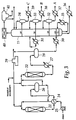
- the process configuration used for dearomatization of solvent and middle distillates comprises two trickle-bed hydrogenation reactors 1, 2 in cascade and a distillation column 3 for stabilization of the dearomatized product.
- the petroleum distillate feedstock is conducted to the first trickle-bed reactor 1 with the aid of a pump 5.
- the liquid stream is heated in a heat exchanger 4 to feed temperature before it is combined with recycle hydrogen feeds and makeup hydrogen.
- the feed stream can be combined with makeup hydrogen and recycle hydrogen before it is heated in the heat exchanger 4.
- the makeup hydrogen feed line is preferably connected to the feed conduit before heat exchanger 4.
- the temperature rise across the reactor is controlled by liquid recycle in which cooled liquid product is recycled from a gas separator vessel 6 or distillation column 3 bottom (the latter recycle is not depicted in the figure) to the reactor inlet.
- Liquid recycle rate is 0.5 to 3 times the fresh feed rate.
- two reactors 1, 2 in series are used.
- This embodiment makes it possible to obtain temperature control of the reactors by liquid recycle which is more accurate than with other systems.
- the two reactors can also be arranged in parallel so that catalyst can be changed without shut down the whole unit.
- Reactor 1 temperature outlet is cooled down to 130 °C in heat exchanger 4.
- Liquid recycle is separated from the liquid effluent in a gas/liquid separator 6 and fed to reactor 1 inlet.
- the second reactor 2 is operated in the same way as the first. Hydrogen-rich gas is separated from the liquid effluent in a gas separator 8 and recycled to the reactor 1 inlet.
- Reference numeral 9 indicates a compressor in the gas line. To remove impurities in recycle gas some of the gas is bled to fuel gas or hydrogen net, as shown in Figure 1.
- Liquid effluent obtained from the second reactor is fed to product stabilization section 3
- the stabilization section is maintained under process conditions sufficient to produce products substantially free of hydrogen and light hydrocarbons.
- the overhead product of the distillation column 3 is divided after condensation 10 in the reflux drum 11 into non-condensable gases, which are used as fuel gases, and light liquid hydrocarbons, which can be used as naphta.
- the dearomatized solvent or middle distillate product is removed as the bottoms product.
- Figure 2 depicts a similar but simplified process configuration which is particularly suitable for hydrogenation of naphtha-type feedstocks.
- the process comprises one hydrogenation reactor 12 with a stabilization section 13, 19 and 20 as explained above.
- This embodiment is operated in the same way as the above:
- the petroleum distillate feedstock is fed to the hydrogenation reactor 12 with the aid of a pump 15.
- the liquid stream is combined with makeup hydrogen and recycle hydrogen feeds and then heated in a heat exchanger 14 to feed temperature.
- the liquid effluent of the reactor is cooled in heat exchangers 14 and 16 and the gas phase is separated from the liquid phase in a gas separator vessel 17. A part of both the cooled liquid effluent and the hydrogen gas is recirculated to the reactor 12 inlet.
- the dearomatized liquid effluent is conducted to a distillation column 13, in which hydrogen gas and light hydrocarbons are separated from the dearomatized product, which comprises, e.g., (cyclo)hexane or methylcyclohexane or naphtha.
- Figure 3 shows a process scheme for the alternative embodiment, wherein the petroleum feedstock is first dearomatized in a hydrogenation section similar to the one described in Figure 1 and then distilled in a distillation section to produce different cuts.
- Reference numerals 21 and 22 relate to two hydrogenation reactors in cascade.
- Numeral 23 designates the distillation column for splitting the dearomatized feed from the dearomatization section.
- the petroleum feedstock is fed to the first dearomatization reactor 21 with the aid of a pump 25.
- the liquid stream is combined with hydrogen feeds and heated in a heat exchanger 24 to proper feed temperature.
- the temperature rise across the reactor is controlled by liquid recycle from gas separator 26 to reactor 21 inlet.
- the second reactor 22 is operated in the same way as the first.
- the hydrogen-rich gas separated from the liquid effluent in gas separator 28 is recycled back to the inlet of reactor 21 via a compressor 29 in the gas line.
- the liquid effluent from gas separator 29 is fed to the distillation column 23 via a heat exchanger 30.
- the distillation section (reference numerals 23 - 40) comprises a distillation column 23, side strippers 32 - 34 and an overhead accumulator 41.
- the distillation column is provided with a reboiler (heater) 35 at the bottom and another in the middle 31.
- the side strippers 32 - 34 comprise liquid/gas separators wherein the condensed liquid stream is separated from the gas, which is recycled to the distillation column.
- Each liquid stream is cooled in a heat exchanger 37 - 39 to form distillation cuts A to C with different boiling point ranges.
- the bottom product of the distillation column forms the heaviest cut and it is also cooled in a separate heat exchanger 36.
- the liquified overhead is collected with a fan 40 in a reflux drum 41. In the drum 41 light hydrocarbons are separated from water.
- the dearomatized feed of the distillation section comprises a hydrocarbon fraction with a boiling point range of about 20 to 300 °C
- the following products can be recovered: middle distillation products as bottoms products, three solvent products as side drawoffs A to C, and naphtha and fuel gas from the overhead.
- a feedstock containing 22 vol.-% aromatics was hydrogenated in the dearomatization unit.
- the density of solvent feed was 780 kg/m 3 at 15 °C and its b.p. range was ASTM D86 distillation, vol.-% IBP 150 °C 10 161 °C 30 169 °C 50 173 °C 70 179 °C 90 190 °C 95 193 °C FBP 197 °C
- Make-up hydrogen feed mol. wt 4.8, used contained hydrogen 90.9 mol-% methane 3.2 mol-% ethane 3.0 mol-% propane 1.6 mol-% butane 0.6 mol-% pentane 0.7 mol-%
- Solvent feedstock containing less than 5 ppmwt sulphur was heated to 130 °C with hydrogen mixture containing make-up hydrogen and recycle hydrogen. Heated two phase mixture was fed into the first reactor of the dearomatization unit, in which aromatics were hydrogenated from the hydrocarbon feedstock in the presence of an active HTC-400 type nickel catalyst. Reactor pressure was 40 bar. Temperature rise across the reactor was 30 °C. Temperature rise across the reactor was controlled by liquid recycle comprising recycling cooled liquid effluent from a gas/liquid separator to the first reactor. Thus, the first reactor outlet was cooled to 130 °C in heat exchanger and liquid recycle was separated in a high pressure separator and recycled back to the inlet of the first reactor.
- Hydrocarbons and hydrogen-rich gas were mixed and fed to the second reactor of the unit, in which dearomatization reactions were completed in the presence of an active HTC-400 type nickel catalyst.
- Reactor pressure was 36 bar and temperature rise in the reactor was 8 °C.
- Reactor outlet was cooled to 40 °C in a heat exchanger. Hydrogen-rich gas containing 87 mol-% hydrogen was separated from the liquid effluent in a gas separator and recycled back to the first reactor inlet. The liquid stream was fed to a stabilization section where light components were removed from the dearomatized product.
- the stabilization section consisted of a distillation column, a reboiler, a condenser and an overhead drum. In the stabilization column hydrogen and light hydrocarbons were distilled from dearomatized solvent product in 200 kPa pressure. Distillation feed temperature was 160 °C. Solvent product b.p. point range was 150 to 200 °C, sp.gr. 0.780 and aromatics content was 0.5 vol.-% or less.
- a solvent feedstock was heated to 130 °C with hydrogen mixture containing make-up hydrogen and recycle hydrogen.
- the heated two phase mixture was fed into the first reactor containing an HTC-400 type nickel catalyst.
- Reactor pressure was 40 bar.
- Temperature rise across the reactor was 32 °C and it was controlled by liquid recycle.
- the first reactor outlet was cooled to 132 °C in the heat exchanger and a liquid stream was separated in gas separator and recycled back to the first reactor inlet.
- Hydrocarbons and hydrogen-rich gas were mixed and fed into the second reactor filled with an HTC-400 type nickel catalyst.
- Reactor pressure was 36 bar and temperature rise in the reactor was 9 °C.
- the outlet of the second reactor was cooled to 40 °C in a heat exchanger. Hydrogen-rich gas containing 87 mol-% hydrogen was separated from the liquid effluent in the gas separator and recycled back to the first reactor inlet. The liquid stream was fed to the stabilization section where light components were removed from the dearomatized solvent product in 200 kPa pressure. Distillation feed temperature was 200 °C. Product aromatics content was 0.5 vol.-% or less.
- a third testrun was done in the same unit with the feedstock containing middle distillates.
- the feedstock used contained aromatics 24 vol.-% and sulphur 5 ppmwt.
- Middle distillate feedstock was heated to 170 °C with hydrogen mixture contained make-up hydrogen and recycle hydrogen. Heated two phase mixture was fed into the first reactor contained an HTC-400 type nickel catalyst. Reactor pressure was 40 bar. Temperature rise across the reactor, controlled by liquid recycle, was 34 °C.
- the first reactor outlet was cooled to 174 °C in the heat exchanger and liquid recycle was separated in the gas separator and recycled back to the first reactor inlet. Hydro-carbons and hydrogen-rich gas were mixed and fed into the second reactor containing an HTC-400 type nickel catalyst. Reactor pressure was 36 bar and temperature rise in the reactor was 3 °C.
- Reactor outlet was cooled to 40 °C in the heat exchanger. Hydrogen-rich gas containing 87 mol-% hydrogen was separated from the liquid effluent in the gas separator and recycled back to the first reactor inlet. Liquid stream was fed to the stabilization section, wherein light components, e.g. hydrogen, C 1 to C 5 hydrocarbons and naphtha components, were removed from the dearomatized middle distillate product. Distillation temperature was 240 °C. Product aromatics content was 5 vol.-%.
- a testrun for benzene hydrogenation of hexane feed was performed in the Figure 1 type unit without recycle gas and with only one reactor. Benzene was hydrogenated to cyclohexane in a trickle-bed reactor containing an HTC-400 type nickel catalyst. Sulphur content of the feed was less than 5 ppmwt.
- the hexane feed used contained isopentane 0.5 wt-% n-pentane 3.0 wt-% cyclopentane 4.0 wt-% methylcyclopentane 9.0 wt-% cyclohexane 7.0 wt-% benzene 8.6 wt-% n-hexane 24.0 wt-% other C 6 hydrocarbons 39.6 wt-% C 7 hydrocarbons 4.3 wt-%
- the make-up hydrogen used contained hydrogen 90.8 mol-% methane 2.8 mol-% ethane 2.5 mol-% propane 2.0 mol-% isobutane 0.5 mol-% n-butane 0.4 mol-% pentane 0.4 mol-% hexane 0.6 mol-%
- the hexane feed was heated to 90 °C with make-up hydrogen in the heat exchanger and fed into the reactor.
- Reactor pressure was 2100 kPa.
- Benzene hydrogenation to cyclohexane is an exothermic reaction and temperature rise across the reactor was 31 °C.
- Temperature rise across the reactor was controlled by liquid recycle in which hydrogenated liquid effluent was recycled back to the reactor inlet.
- Reactor outlet was cooled in the heat exchanger. Hydrogen-rich gas was separated from the liquid stream in the gas separator. Hydrogen-rich gas containing 87.8 mol-% hydrogen was fed to hydrogen net. In the gas separator liquid recycle was separated from the hydrogenated liquid stream and fed to the reactor inlet.
- the hydrogenated product was fed to the product stabilization section where light hydrocarbons were distilled from hexane product at 600 kPa pressure. Benzene content of the hexane product was 0.1 wt-%.
- a second testrun for benzene hydrogenation was carried out with reformate feed having a b.p. range of 55 to 222 °C, sp.gr. of 0.831 and a benzene content of 4.0 wt-%.
- Reformate feed was heated to 90 °C with make-up hydrogen in the heat exchanger and fed into the trickle-bed reactor filled with HTC-400 type nickel catalyst.
- Reactor pressure was 2100 kPa.
- Temperature rise across the reactor was 19 °C and it was controlled by liquid recycle.
- Reactor outlet was cooled in the heat exchanger. Hydrogen-rich gas was separated from the product in the gas separator. Hydrogen-rich gas was fed to hydrogen net and liquid recycle was to the reactor inlet.
- the hydrogenated liquid stream was fed to the product stabilization section where light hydrocarbons were distilled from reformate product at 600 kPa pressure.
- Product benzene content was 0.1 wt-% or less.
- a third testrun for benzene hydrogenation was constituted by light solvents containing 3.9 wt-% benzene.
- the b.p. range of the feedstock used was 88 to 105 °C and sp.gr. 0.720.
- the solvent feed was heated to 110 °C with make-up hydrogen and fed into the trickle-bed reactor containing HTC-400 type nickel catalyst.
- Reactor pressure was 2100 kPa.
- Reactor outlet was cooled in the heat exchanger. Hydrogen-rich gas was separated from the product in the gas separator. Hydrogen-rich gas was fed to hydrogen net. In the separator liquid recycle was separated from the hydrogenated liquid stream and fed to the reactor inlet.
- the hydrogenated product was fed to the product stabilization section where light hydrocarbons were distilled from solvent product at 600 kPa pressure.
- Product benzene content was 0.01 wt-%.
- a fourth testrun for benzene hydrogenation was done with light solvents contained 7.6 wt-% benzene.
- the density of the feedstock used was 0.680 and its b.p. range was 65 to 75°C.
- the solvent feed was heated to 110 °C with make-up hydrogen in the heat exchanger. Heated mixture was fed to the trickle-bed reactor filled with HTC-400 type nickel catalyst. Reactor pressure was 2100 kPa. Temperature rise across the reactor was 28°C and it was controlled by liquid recycle.
- Reactor outlet was cooled in the heat exchanger. Hydrogen-rich gas was separated from the liquid effluent in the gas separator. Liquid recycle was separated from the hydrogenated liquid effluent and fed to the reactor inlet.
- the hydrogenated product was fed to the product stabilization section where light hydrocarbons were distilled from solvent product at 600 kPa pressure. Benzene content of light solvent was 0.01 wt-%.
- the liquid feed of the simulated reactor was 100 tons/h and it consisted of toluene (5.0 w-%), methylcyclohexane and ten inert hydrocarbon compounds.
- the gas feed contained 95 mol-% hydrogen and a small amount of light hydrocarbons.
- the gas feed rate was 1.0 tons/h.
- the temperature of the liquid and the gas feed was 110 °C.
- the operating pressure was 3100 kPa.
- the results of the reactor model suggested that the 85 % conversion of toluene was reached with the reactor lenght of 2 m and the reactor length of around 4 m was sufficient for the 99 % conversion of toluene.
- the increase in temperature was about 38 °C.
- the computed pressure drop in the reactor was 80 kPa.
- the following example relates to a dearomatization process depicted in Figure 3, in which the petroleum feedstock is first fed into a trickle-bed reactor and then the liquid stream was split into dearomatized petroleum distillates; solvents, naphtha and middle distillate products. Feed capacity of the unit was 50 tons/hr.
- the characteristics of the petroleum feedstock were as follows: density at 15 °C is 808 kg/m 3 and b.p. range (ASTM D86 distillation) 145 to 320 °C. It contained 20 vol-% aromatics and 5 ppmwt sulphur.
- the make-up hydrogen feed used contained hydrogen 93.0 mol-% methane 3.1 mol-% ethane 1.5 mol-% propane 1.3 mol-% butane 0.8 mol-% pentane 0.3 mol-%
- the petroleum feedstock was heated to 150 °C with a hydrogen mixture containing make-up hydrogen and recycle hydrogen.
- the heated two-phase mixture was fed into the reactor, in which aromatics were hydrogenated from the hydrocarbon feedstock in the presence of an active HTC-400 type nickel catalyst.
- Reactor pressure was 40 bar.
- Temperature rise across the reactor was 34 °C and it was controlled by liquid recycle in which cooled liquid effluent was recycled from separator to the reactor inlet
- Reactor outlet was cooled to 40 °C in a heat exchanger. Hydrogen rich gas containing 87 mol-% hydrogen was separated from the liquid effluent in a gas separator and recycled back to the reactor inlet. Liquid effluent was fed to the distillation section, wherein the liquid stream was split into petroleum distillates.
- the liquid feed was heated to 175 °C in a heat exchanger and fed into a distillation column in which liquid stream was distilled into dearomatized naphtha, solvent and middle distillate products at a pressure of 160 kPa.
- the column diameter was 3 m and the height 50 m.
- the column consisted of 72 trays and pump-around with cooler of 2.3 MW from tray no 38. The feed was into 68 th tray.
- column consisted of three side-draw-off trays no 58, 38 and 18, from which three solvent products A, B and C with different b.p. range were removed. Each solvent product was stabilized in steam stripper with 8 trays. Sidestrippers for solvents A and B diameter was 1.0 m and height 6.0 m. Solvent C sidestrippers diameter was 1.1 m and height 6.0 m. Distilled products are specified in table 1.
- Top temperature of the column was 120 °C and overhead condenser duty was 10 MW.
- the overhead product was unstabilized naphtha which was fed to stabilization section where light hydrocarbons were removed from the dearomatized naphtha product. It is also possible to feed distillation feedstock first to the product stabilizer and then, after stabilization, to conduct the feed to the distillation column in order to split petroleum distillates.
- Table 2 Properties of distillated dearomatized product Product Rate, tons/hr. Aromatics, vol-% B.p. range, °C Sp.
Applications Claiming Priority (2)
| Application Number | Priority Date | Filing Date | Title |
|---|---|---|---|
| FI961012 | 1996-03-05 | ||
| FI961012A FI100535B (fi) | 1996-03-05 | 1996-03-05 | Menetelmä öljytisleiden dearomatisoimiseksi |
Publications (2)
| Publication Number | Publication Date |
|---|---|
| EP0794241A2 true EP0794241A2 (fr) | 1997-09-10 |
| EP0794241A3 EP0794241A3 (fr) | 1998-02-11 |
Family
ID=8545584
Family Applications (1)
| Application Number | Title | Priority Date | Filing Date |
|---|---|---|---|
| EP97660024A Withdrawn EP0794241A3 (fr) | 1996-03-05 | 1997-03-05 | Procédé pour la désaromatisation de distillats pétrolières |
Country Status (2)
| Country | Link |
|---|---|
| EP (1) | EP0794241A3 (fr) |
| FI (1) | FI100535B (fr) |
Cited By (14)
| Publication number | Priority date | Publication date | Assignee | Title |
|---|---|---|---|---|
| WO1999049002A1 (fr) * | 1998-03-20 | 1999-09-30 | Fortum Oil And Gas Oy | Procede d'hydrogenation |
| WO2000012651A1 (fr) * | 1998-08-28 | 2000-03-09 | Exxon Chemical Patents Inc. | Utilisation de la distillation catalytique pour eliminer par hydrogenation des impuretes dans des solvants |
| DE102007027372A1 (de) * | 2007-06-11 | 2008-12-18 | Cognis Oleochemicals Gmbh | Verfahren zur Hydrierung von Glycerin |
| US8536390B2 (en) | 2010-03-18 | 2013-09-17 | Syntroleum Corporation, A Delaware Corporation | Profitable method for carbon capture and storage |
| US8558042B2 (en) | 2008-06-04 | 2013-10-15 | Syntroleum Corporation | Biorenewable naphtha |
| US8575409B2 (en) | 2007-12-20 | 2013-11-05 | Syntroleum Corporation | Method for the removal of phosphorus |
| US8859832B2 (en) | 2005-07-05 | 2014-10-14 | Neste Oil Oyj | Process for the manufacture of diesel range hydrocarbons |
| WO2014174178A1 (fr) * | 2013-04-26 | 2014-10-30 | Axens | Procede d'hydrogenation d'une charge d'hydrocarbures comprenant des composes aromatiques |
| US8969259B2 (en) | 2013-04-05 | 2015-03-03 | Reg Synthetic Fuels, Llc | Bio-based synthetic fluids |
| US9133080B2 (en) | 2008-06-04 | 2015-09-15 | Reg Synthetic Fuels, Llc | Biorenewable naphtha |
| US9328303B2 (en) | 2013-03-13 | 2016-05-03 | Reg Synthetic Fuels, Llc | Reducing pressure drop buildup in bio-oil hydroprocessing reactors |
| US9963401B2 (en) | 2008-12-10 | 2018-05-08 | Reg Synthetic Fuels, Llc | Even carbon number paraffin composition and method of manufacturing same |
| EP3549997A1 (fr) * | 2018-04-05 | 2019-10-09 | Neste Oyj | Procédé et appareil d'hydrogénation |
| US20230193146A1 (en) * | 2021-12-18 | 2023-06-22 | Indian Oil Corporation Limited | Product of low benzene content de-aromatized distillates for specialty applications |
Citations (2)
| Publication number | Priority date | Publication date | Assignee | Title |
|---|---|---|---|---|
| US4036734A (en) * | 1973-11-02 | 1977-07-19 | Exxon Research And Engineering Company | Process for manufacturing naphthenic solvents and low aromatics mineral spirits |
| US5449452A (en) * | 1993-09-20 | 1995-09-12 | Sudhakar; Chakka | Hydrodearomatization of hydrocarbons |
-
1996
- 1996-03-05 FI FI961012A patent/FI100535B/fi active
-
1997
- 1997-03-05 EP EP97660024A patent/EP0794241A3/fr not_active Withdrawn
Patent Citations (2)
| Publication number | Priority date | Publication date | Assignee | Title |
|---|---|---|---|---|
| US4036734A (en) * | 1973-11-02 | 1977-07-19 | Exxon Research And Engineering Company | Process for manufacturing naphthenic solvents and low aromatics mineral spirits |
| US5449452A (en) * | 1993-09-20 | 1995-09-12 | Sudhakar; Chakka | Hydrodearomatization of hydrocarbons |
Cited By (39)
| Publication number | Priority date | Publication date | Assignee | Title |
|---|---|---|---|---|
| WO1999049002A1 (fr) * | 1998-03-20 | 1999-09-30 | Fortum Oil And Gas Oy | Procede d'hydrogenation |
| WO2000012651A1 (fr) * | 1998-08-28 | 2000-03-09 | Exxon Chemical Patents Inc. | Utilisation de la distillation catalytique pour eliminer par hydrogenation des impuretes dans des solvants |
| US11473018B2 (en) | 2005-07-05 | 2022-10-18 | Neste Oyj | Process for the manufacture of diesel range hydrocarbons |
| US10800976B2 (en) | 2005-07-05 | 2020-10-13 | Neste Oyj | Process for the manufacture of diesel range hydrocarbons |
| US10059887B2 (en) | 2005-07-05 | 2018-08-28 | Neste Oyj | Process for the manufacture of diesel range hydrocarbons |
| US10550332B2 (en) | 2005-07-05 | 2020-02-04 | Neste Oyj | Process for the manufacture of diesel range hydrocarbons |
| US8859832B2 (en) | 2005-07-05 | 2014-10-14 | Neste Oil Oyj | Process for the manufacture of diesel range hydrocarbons |
| US9598327B2 (en) | 2005-07-05 | 2017-03-21 | Neste Oil Oyj | Process for the manufacture of diesel range hydrocarbons |
| DE102007027372A1 (de) * | 2007-06-11 | 2008-12-18 | Cognis Oleochemicals Gmbh | Verfahren zur Hydrierung von Glycerin |
| US8575409B2 (en) | 2007-12-20 | 2013-11-05 | Syntroleum Corporation | Method for the removal of phosphorus |
| US8629308B2 (en) | 2007-12-20 | 2014-01-14 | Syntroleum Corporation | Method for the conversion of polymer contaminated feedstocks |
| US8581013B2 (en) | 2008-06-04 | 2013-11-12 | Syntroleum Corporation | Biorenewable naphtha composition and methods of making same |
| US9061951B2 (en) | 2008-06-04 | 2015-06-23 | Reg Synthetic Fuels, Llc | Biorenewable naphtha composition |
| US9133080B2 (en) | 2008-06-04 | 2015-09-15 | Reg Synthetic Fuels, Llc | Biorenewable naphtha |
| US8558042B2 (en) | 2008-06-04 | 2013-10-15 | Syntroleum Corporation | Biorenewable naphtha |
| US9963401B2 (en) | 2008-12-10 | 2018-05-08 | Reg Synthetic Fuels, Llc | Even carbon number paraffin composition and method of manufacturing same |
| US10717687B2 (en) | 2008-12-10 | 2020-07-21 | Reg Synthetic Fuels, Llc | Even carbon number paraffin composition and method of manufacturing same |
| US11623899B2 (en) | 2008-12-10 | 2023-04-11 | Reg Synthetic Fuels, Llc | Even carbon number paraffin composition and method of manufacturing same |
| US11097994B2 (en) | 2008-12-10 | 2021-08-24 | Reg Synthetic Fuels, Llc | Even carbon number paraffin composition and method of manufacturing same |
| US8536390B2 (en) | 2010-03-18 | 2013-09-17 | Syntroleum Corporation, A Delaware Corporation | Profitable method for carbon capture and storage |
| US9328303B2 (en) | 2013-03-13 | 2016-05-03 | Reg Synthetic Fuels, Llc | Reducing pressure drop buildup in bio-oil hydroprocessing reactors |
| US9523041B2 (en) | 2013-03-13 | 2016-12-20 | Reg Synthetic Fuels, Llc | Reducing pressure drop buildup in bio-oil hydroprocessing reactors |
| US10011783B2 (en) | 2013-04-05 | 2018-07-03 | Reg Synthetic Fuels, Llc | Bio-based synthetic fluids |
| US11186785B2 (en) | 2013-04-05 | 2021-11-30 | Reg Synthetic Fuels, Llc | Bio-based synthetic fluids |
| US8969259B2 (en) | 2013-04-05 | 2015-03-03 | Reg Synthetic Fuels, Llc | Bio-based synthetic fluids |
| WO2014174178A1 (fr) * | 2013-04-26 | 2014-10-30 | Axens | Procede d'hydrogenation d'une charge d'hydrocarbures comprenant des composes aromatiques |
| TWI646186B (zh) * | 2013-04-26 | 2019-01-01 | 艾克森斯公司 | 用於氫化包含芳香化合物之烴饋料之方法 |
| FR3005059A1 (fr) * | 2013-04-26 | 2014-10-31 | Axens | Procede d'hydrogenation d'une charge d'hydrocarbures comprenant des composes aromatiques |
| FR3005060A1 (fr) * | 2013-04-26 | 2014-10-31 | Axens | Procede d'hydrogenation d'une charge d'hydrocarbures comprenant des composes aromatiques |
| JP2016522846A (ja) * | 2013-04-26 | 2016-08-04 | アクセンス | 芳香族化合物を含む炭化水素供給原料の水素化方法 |
| US9732286B2 (en) | 2013-04-26 | 2017-08-15 | Axens | Process for hydrogenation of a hydrocarbon feedstock comprising aromatic compounds |
| EP3549997A1 (fr) * | 2018-04-05 | 2019-10-09 | Neste Oyj | Procédé et appareil d'hydrogénation |
| CN110343546B (zh) * | 2018-04-05 | 2021-04-02 | 耐思特公司 | 用于氢化的方法和装置 |
| US10793789B2 (en) | 2018-04-05 | 2020-10-06 | Nestec Oyj | Process and apparatus for hydrogenation |
| CN110343546A (zh) * | 2018-04-05 | 2019-10-18 | 奈斯特化学公司 | 用于氢化的方法和装置 |
| KR20190116910A (ko) * | 2018-04-05 | 2019-10-15 | 네스테 오와이제이 | 수소화 공정 및 장치 |
| KR102071370B1 (ko) | 2018-04-05 | 2020-01-30 | 네스테 오와이제이 | 수소화 공정 및 장치 |
| US20230193146A1 (en) * | 2021-12-18 | 2023-06-22 | Indian Oil Corporation Limited | Product of low benzene content de-aromatized distillates for specialty applications |
| US11866658B2 (en) | 2021-12-18 | 2024-01-09 | Indian Oil Corporation Ltd. | Product of low benzene content de-aromatized distillates for specialty applications |
Also Published As
| Publication number | Publication date |
|---|---|
| FI961012A0 (fi) | 1996-03-05 |
| EP0794241A3 (fr) | 1998-02-11 |
| FI100535B (fi) | 1997-12-31 |
| FI961012A (fi) | 1997-09-06 |
Similar Documents
| Publication | Publication Date | Title |
|---|---|---|
| CA1092786A (fr) | Methode pour accroitre la purete de l'hydrogene moleculaire, recircule | |
| US5968347A (en) | Multi-step hydrodesulfurization process | |
| KR100516658B1 (ko) | 포화올리고머의개선된제조방법 | |
| RU2174534C2 (ru) | Способ параллельной гидрообработки (варианты), установка гидрообработки | |
| US20030000867A1 (en) | Crude oil desulfurization | |
| US4082647A (en) | Simultaneous and continuous hydrocracking production of maximum distillate and optimum lube oil base stock | |
| EP0794241A2 (fr) | Procédé pour la désaromatisation de distillats pétrolières | |
| US6514403B1 (en) | Hydrocracking of vacuum gas and other oils using a cocurrent/countercurrent reaction system and a post-treatment reactive distillation system | |
| US3732155A (en) | Two-stage hydrodesulfurization process with hydrogen addition in the first stage | |
| EP0083762A1 (fr) | Récupération des produits de conversion d'hydrocarbures en C3+ et d'un net excès d'hydrogène dans un procédé de reformage catalytique | |
| US4588560A (en) | Hydroprocessing reactor for catalytically dewaxing liquid petroleum feedstocks | |
| US20060183952A1 (en) | Process for the removal of benzene from gasoline streams | |
| US20070209966A1 (en) | Catalytic distillation process for hydroprocessing Fischer-Tropsch liquids | |
| US6413413B1 (en) | Hydrogenation process | |
| AU2002211876A1 (en) | Two stage hydroprocessing and stripping in a single reaction vessel | |
| EP1343856A1 (fr) | Hydrotraitement et revaporisation en deux etapes dans une seule cuve a reaction | |
| CN104726132B (zh) | 烃馏分的加氢脱硫方法 | |
| EP4130203A2 (fr) | Procédé de saturation d'aromatiques dans un flux de pyrolyse | |
| US3926785A (en) | Integrated distillation and hydrodesulfurization process for jet fuel production | |
| US4333817A (en) | Separation of normally gaseous hydrocarbons from a catalytic reforming effluent and recovery of purified hydrogen | |
| US5246567A (en) | Benzene removal in an isomerization process | |
| US4902405A (en) | Fixed bed hydrocracking process | |
| CN115504851A (zh) | 用于从异构化流出物料流中的正链烷烃去除烯烃的方法 | |
| CN115305105A (zh) | 由废油制备的溶剂组合物及其制备方法 | |
| RU2307820C1 (ru) | Способ получения высокооктановых изокомпонентов бензина |
Legal Events
| Date | Code | Title | Description |
|---|---|---|---|
| PUAI | Public reference made under article 153(3) epc to a published international application that has entered the european phase |
Free format text: ORIGINAL CODE: 0009012 |
|
| AK | Designated contracting states |
Kind code of ref document: A2 Designated state(s): DE ES FR GB IT NL SE |
|
| PUAL | Search report despatched |
Free format text: ORIGINAL CODE: 0009013 |
|
| AK | Designated contracting states |
Kind code of ref document: A3 Designated state(s): DE ES FR GB IT NL SE |
|
| STAA | Information on the status of an ep patent application or granted ep patent |
Free format text: STATUS: THE APPLICATION IS DEEMED TO BE WITHDRAWN |
|
| 18D | Application deemed to be withdrawn |
Effective date: 19980812 |