EP0794057B1 - Dispositif d'écriture par jet d'encre avec élément chauffant à surface profilée - Google Patents
Dispositif d'écriture par jet d'encre avec élément chauffant à surface profilée Download PDFInfo
- Publication number
- EP0794057B1 EP0794057B1 EP96306875A EP96306875A EP0794057B1 EP 0794057 B1 EP0794057 B1 EP 0794057B1 EP 96306875 A EP96306875 A EP 96306875A EP 96306875 A EP96306875 A EP 96306875A EP 0794057 B1 EP0794057 B1 EP 0794057B1
- Authority
- EP
- European Patent Office
- Prior art keywords
- ink jet
- thermal ink
- jet printhead
- contoured surface
- defining
- Prior art date
- Legal status (The legal status is an assumption and is not a legal conclusion. Google has not performed a legal analysis and makes no representation as to the accuracy of the status listed.)
- Expired - Lifetime
Links
- 238000010304 firing Methods 0.000 claims description 26
- 238000010438 heat treatment Methods 0.000 claims description 11
- 239000000758 substrate Substances 0.000 claims description 10
- 238000005530 etching Methods 0.000 claims description 6
- 238000004519 manufacturing process Methods 0.000 claims description 5
- 230000001154 acute effect Effects 0.000 claims description 4
- 238000004891 communication Methods 0.000 claims description 3
- 239000012530 fluid Substances 0.000 claims description 2
- 239000000463 material Substances 0.000 claims 1
- 230000006911 nucleation Effects 0.000 description 21
- 238000010899 nucleation Methods 0.000 description 21
- 238000009835 boiling Methods 0.000 description 9
- 230000004888 barrier function Effects 0.000 description 8
- 238000000034 method Methods 0.000 description 7
- 230000015572 biosynthetic process Effects 0.000 description 6
- 230000007547 defect Effects 0.000 description 6
- 238000002161 passivation Methods 0.000 description 6
- 230000008569 process Effects 0.000 description 5
- 239000010408 film Substances 0.000 description 3
- 238000007641 inkjet printing Methods 0.000 description 3
- XAGFODPZIPBFFR-UHFFFAOYSA-N aluminium Chemical compound [Al] XAGFODPZIPBFFR-UHFFFAOYSA-N 0.000 description 2
- 229910052782 aluminium Inorganic materials 0.000 description 2
- 230000008901 benefit Effects 0.000 description 2
- 230000001186 cumulative effect Effects 0.000 description 2
- 230000003111 delayed effect Effects 0.000 description 2
- 238000003384 imaging method Methods 0.000 description 2
- 230000007246 mechanism Effects 0.000 description 2
- 230000002123 temporal effect Effects 0.000 description 2
- 229910004490 TaAl Inorganic materials 0.000 description 1
- 239000003086 colorant Substances 0.000 description 1
- 230000000694 effects Effects 0.000 description 1
- 230000006872 improvement Effects 0.000 description 1
- 239000007788 liquid Substances 0.000 description 1
- 238000007639 printing Methods 0.000 description 1
- 230000001681 protective effect Effects 0.000 description 1
- 230000000284 resting effect Effects 0.000 description 1
- 230000035945 sensitivity Effects 0.000 description 1
- 238000000926 separation method Methods 0.000 description 1
- 229910052715 tantalum Inorganic materials 0.000 description 1
- GUVRBAGPIYLISA-UHFFFAOYSA-N tantalum atom Chemical compound [Ta] GUVRBAGPIYLISA-UHFFFAOYSA-N 0.000 description 1
- 239000010409 thin film Substances 0.000 description 1
- 230000007704 transition Effects 0.000 description 1
Images


Classifications
-
- B—PERFORMING OPERATIONS; TRANSPORTING
- B41—PRINTING; LINING MACHINES; TYPEWRITERS; STAMPS
- B41J—TYPEWRITERS; SELECTIVE PRINTING MECHANISMS, i.e. MECHANISMS PRINTING OTHERWISE THAN FROM A FORME; CORRECTION OF TYPOGRAPHICAL ERRORS
- B41J2/00—Typewriters or selective printing mechanisms characterised by the printing or marking process for which they are designed
- B41J2/005—Typewriters or selective printing mechanisms characterised by the printing or marking process for which they are designed characterised by bringing liquid or particles selectively into contact with a printing material
- B41J2/01—Ink jet
- B41J2/135—Nozzles
- B41J2/16—Production of nozzles
- B41J2/1601—Production of bubble jet print heads
- B41J2/1603—Production of bubble jet print heads of the front shooter type
-
- B—PERFORMING OPERATIONS; TRANSPORTING
- B41—PRINTING; LINING MACHINES; TYPEWRITERS; STAMPS
- B41J—TYPEWRITERS; SELECTIVE PRINTING MECHANISMS, i.e. MECHANISMS PRINTING OTHERWISE THAN FROM A FORME; CORRECTION OF TYPOGRAPHICAL ERRORS
- B41J2/00—Typewriters or selective printing mechanisms characterised by the printing or marking process for which they are designed
- B41J2/005—Typewriters or selective printing mechanisms characterised by the printing or marking process for which they are designed characterised by bringing liquid or particles selectively into contact with a printing material
- B41J2/01—Ink jet
- B41J2/135—Nozzles
- B41J2/14—Structure thereof only for on-demand ink jet heads
- B41J2/14016—Structure of bubble jet print heads
- B41J2/14088—Structure of heating means
- B41J2/14112—Resistive element
- B41J2/1412—Shape
-
- B—PERFORMING OPERATIONS; TRANSPORTING
- B41—PRINTING; LINING MACHINES; TYPEWRITERS; STAMPS
- B41J—TYPEWRITERS; SELECTIVE PRINTING MECHANISMS, i.e. MECHANISMS PRINTING OTHERWISE THAN FROM A FORME; CORRECTION OF TYPOGRAPHICAL ERRORS
- B41J2/00—Typewriters or selective printing mechanisms characterised by the printing or marking process for which they are designed
- B41J2/005—Typewriters or selective printing mechanisms characterised by the printing or marking process for which they are designed characterised by bringing liquid or particles selectively into contact with a printing material
- B41J2/01—Ink jet
- B41J2/135—Nozzles
- B41J2/16—Production of nozzles
- B41J2/1621—Manufacturing processes
- B41J2/1626—Manufacturing processes etching
Definitions
- This invention relates to thermal ink jet printing, and more particularly to heater elements for thermal ink jet printheads.
- Ink jet printing mechanisms use pens that shoot droplets of colorant onto a printable surface to generate an image. Such mechanisms may be used in a wide variety of applications, including computer printers, plotters, copiers, and facsimile machines. For convenience, the concepts of the invention are discussed in the context of a printer.
- An ink - jet printer typically includes a printhead having a multitude of independently addressable firing units. Each firing unit includes an ink chamber connected to a common ink source, and an ink outlet nozzle or orifice. A transducer within the chamber provides the impetus for expelling ink droplets through the nozzles.
- the transducer is a resistive heater element that provides sufficient heat to rapidly vaporize a small portion of ink within the chamber, forming a bubble.
- the bubble displaces a droplet of liquid ink from the nozzle.
- the timing, magnitude, rate, shape, and position of the bubble formation be as uniform as possible. Uniformity is desired from firing unit to firing unit, and between sequential droplets originating from the same nozzle.
- Heterogeneous nucleate boiling normally occurs at defect sites on the surface of a heating element, or other heated surface. These defects may be cracks, discontinuities, and edges and vertexes where surfaces meet at angle. Heterogeneous nucleate boiling occurs more readily than homogenous or film boiling, which occurs after additional heat energy is added when sufficiently sized nucleation sites are not present. Therefore, it is the heterogeneous nucleation that has the greatest effect during the rapid and uniformity-sensitive boiling process that occurs during thermal ink jet printing.
- EP 638 424A discloses a thermal ink jet printhead and method of manufacture in which an ink feed opening in a thin film substrate is axially aligned with a central opening in a heater resistor disposed on the substrate. The ink feed opening is also aligned with a firing chamber.
- the uniformity disadvantages of prior art systems are reduced or overcome by providing a thermal ink jet as claimed in the appendent claims.
- the ink jet includes a body having an ink firing chamber and an orifice.
- An electrically activated heating element is connected to the body in thermal communication with the firing chamber, and includes a contoured surface portion coextensive with at least a portion of the heating element.
- the contoured surface portion of the firing chamber has a plurality of recesses.
- Figure 1 is a sectional isometric view of a thermal ink jet printhead according to a preferred embodiment of the invention.
- Figure 2 is a sectional side view of the embodiment of Fig. 1 taken along line 2-2.
- Figure 3 is an enlarged sectional side view of the embodiment of Fig. 1 taken along line 2-2.
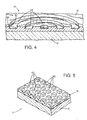
- Figure 4 is a sectional view of a first alternative embodiment of the invention.
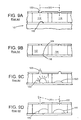
- Figure 5 is a sectional view of a second alternative embodiment of the invention.
- Figure 6 is a sectional view of a third alternative embodiment of the invention.
- Figure 7 is a sectional view of a fourth alternative embodiment of the invention.
- Figure 8 is a sectional view of a fifth alternative embodiment of the invention.
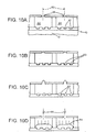
- Figures 9A-9D illustrate a sequence of operation of a prior art apparatus.
- Figures 10A-10D illustrate a sequence of operation of the embodiment of Fig. 1.
- Figure 1 illustrates a thermal ink jet printhead 10 having a rigid planar substrate 12 with a flat upper surface 14.
- a planar heater element 16 is applied to the upper surface of the substrate.
- a barrier layer 20 is applied to the substrate surrounding the heater element 16 to define a firing chamber 22 centered above the heater element.
- An orifice plate 24 is connected to the upper surface of the barrier layer to enclose the firing chamber, and defines an orifice 26 centered above the heater element.
- the firing chamber has at least one lateral opening 30 on at least one side to provide an inlet for ink supplied by an ink supply plenum 32.
- the printhead includes an elongated array of adjacent firing units having the same arrangement of heater element, chamber, and orifice, and supplied by the common plenum.
- the heater element 16 is connected between a pair of conductive aluminum leads 34 that overlay the upper surface 14 of the substrate 12, and which are connected to a powered controller (not shown) that applies a voltage across the heater element when a droplet of ink is required to be expelled from the firing unit.
- the heater element 16 has a flat lower surface 36 and a parallel flat upper surface 14.
- the heater element is a stack of three layers. The lowest layer is a TaAl resistor film 37 resting on the substrate's upper surface 40.
- An electrically insulative passivation layer 38 overlays the resistor, and a mechanically protective tantalum cavitation barrier 39 overlays the passivation layer.
- the cavitation barrier 39 protects the resistor from the stresses of bubble formation and collapse during printing.
- a plurality of separate square recesses 42 are defined in an array that extends across most of the surface of the heater element 16.
- the recesses have flat bottoms or floors 44 parallel to the upper and lower surfaces of the heater element, and extend to a limited depth so that the passivation layer 38 is not exposed within the recesses; in alternative embodiments, the passivation layer may be exposed.
- the periphery of each recess is defined by a vertical side wall 46 that provides a step between the level of the recess floors 44 and the upper surface 40 of the heater element.
- the side wall 46 meets the recess floor 44 at a sharp corner or interior edge 50, and meets the upper surface 40 at a rim edge 52. Both edges are sharp right angles, although variations will be discussed below.
- the sharp edges are slightly radiused due to inherent limitations of the etching process. These sharp edges provide nucleation sites 53 where boiling will tend to occur most rapidly, and at the lowest energy.
- the reduced thickness at the floor of a recess may provide a higher heat due to its proximity to the resistor and the reduced thermal gradient across the cavitation barrier 39 to further expedite boiling at the lower nucleation sites 50.
- the recesses 42 are arranged on a grid, with individual recesses positioned at alternate locations in the manner of a checkerboard.
- the recesses each have a width and length less than or equal to the pitch of the grid on which they are arranged, such that they are spaced apart at their comers to avoid intersecting with the comers of adjacent recesses.
- the etching process used to form the recesses after application of the heater element to the substrate yields recesses with rounded corners as viewed from above, providing separation even between recesses arranged on a grid having the same pitch as the width of the recesses.
- the recesses have a width of between 5 and 10 ⁇ m, although the advantages of the invention will be realized as further miniaturization becomes practical.
- 13 recesses are provided, although more or fewer may be provided in other arrangements
- Figures 4-8 illustrate alternative heater element surface contour patterns.
- Figure 4 shows an alternative printhead with a heater element having a pattern of concentric ring-shaped recesses 56, each having a cross section similar to the recesses 42 of the preferred embodiment.
- the outer rings are large, and each ring functions as many recesses to provide many nucleation sites by having a substantial length of edges 50, 52 for a given major area of the heater element. It is also possible modify the illustrated pattern to form a spiral shape having similar recess and land widths over the same area. Although not literally a plurality of recesses, such a recess is considered a "plurality" for the purposes of this application because of the high ratio of edges 50, 52 to the overall area and linear dimensions of the heater element and of the recessed area.
- a single “recess" or recess segment shall be defined as a basin, pocket, channel, groove, or segment thereof having edges surrounding more then half its periphery.
- an elongated channel may be considered as segmented into multiple individual recesses, each having a length only slightly longer than its width.
- an alternative embodiment heater element has a rectangular array of separate square plateaus 60 defined by a grid of parallel channels 62.
- the grid of channels is considered to be a plurality of recesses, because the edges of the plateaus have a cumulative length much greater than the cumulative length of the edges of a single regular recess such as a square, circle, oblong, or similar simple shape of the same area.
- Figs. 6, 7, and 8 illustrate alternative channel profiles.
- the side walls 64 are undercut, such that they form an acute angle with respect to the flat floor 44.
- An acute lower nucleation site 66 is positioned at least partly below the side wall for enhanced nucleation.
- Side walls may be effectively offset from the perpendicular by any amount, including obtuse angles.
- Figure 7 shows a variation on the undercut of Fig. 6 in which a conventional etching process yields a channel 70 with a curved or elliptical profile, at least at the edges.
- the nucleation sites 72 are located similarly to those in Fig 6, although the illustrated etching technique may provide more acute upper edges 52 to further favor nucleation.
- Fig. 8 illustrates a further alternative embodiment in which the heater element surface 40 is primarily a flat plane, with an array of protruding ridges 74 spaced apart across the surface.
- the ridges of the Fig. 8 embodiment and the recesses of the Fig. 5 and 6 embodiments may all be formed in any of the patterns discussed above and illustrated in Figs. 1-5.
- Figs. 9A-9D show the limitations of a prior art thermal ink jet printhead 110. It is constructed essentially the same as the preferred embodiment of the invention, except that it has a flat heater element surface instead of a contoured surface.
- the prior art printhead 110 has a pair of firing chambers 112, 114. In chamber 114, the heater element has an unintended defect crack 116 offset randomly from a central axis 120 passing through the orifice 122.
- the heater element in the right firing chamber 114 is free of defects. Consequently, as shown in Fig. 9B, simultaneous application of energy to both heater elements results initially in the nucleation of a bubble 124 at the defect 116 in the left chamber 112. Because higher energy is required without a nucleation site, the right chamber has not yet commenced bubble formation.
- the left bubble 124 has grown sufficiently to begin displacing a droplet 126 from the left orifice 122. Meanwhile, a bubble 130 has formed in the right chamber, but is smaller than the left bubble 120 because of its delayed formation due to the higher energy to begin bubble formation without the benefit of a nucleation site.
- the left droplet has been ejected on a path that deviates from the axis because of the off-center location of the bubble. The left droplet 126 is spatially deviated from the location where it is intended to impact the print medium (not shown).
- a right droplet 132 happens to be ejected on axis, but is temporally deviated from its position. As the printhead rapidly traverses over the print medium, delayed droplets will be deposited farther down range along the printhead path than if they were timely expelled.
- the preferred embodiment suffers from neither temporal nor spatial droplet deviation.
- nucleation occurs at many or most of the recesses 42. Even if nucleation does not occur at every site, or in every recess, there are sufficient recesses and sites so that at least some nucleation sites will promptly begin bubble formation, avoiding temporal deviation. The number of sites also ensures that the resulting bubbles are well distributed, even if all sites are not effective for nucleation, avoiding spatial deviation.
- the quantity and wide distribution of recesses provides an accelerated transition from nucleate to film boiling, further improving uniformity.
- Fig. 10C shows small bubbles 82 forming in most or all recesses 42.
- the bubbles 82 have coalesced in each firing chamber.
- the resulting bubbles 84 have a flatter surface or "wave front" to eject droplets 86 reliably on axis.
- the sensitivity of orifice position is reduced. This is an improvement over prior art systems in which positioning the orifice slightly off axis relative to a spherically expanding bubble can generate turbulence and lateral flow in the ink near the orifice.
- the heater element 16 has an overall thickness of about 8-10 ⁇ m.
- the resistor 37 is 0.10 ⁇ m thick
- the passivation 38 is 0.75 ⁇ m thick
- the cavitation barrier 39 is 0.6 ⁇ m thick.
- the aluminum leads 43 are about 0.7mm thick, and are positioned between the resistor layer and the passivation layer.
- adjacent firing units are spaced apart 40-80 ⁇ m on center, each orifice having a diameter of 10-50 ⁇ m, and spaced above the heater element surface by 14-25 ⁇ m.
- the heater element is a square about 20-60 ⁇ m on a side, and the firing chamber has a width or diameter of about 16 ⁇ m greater than the resistor.
- the cavitation barrier may be imaged in two steps: first, imaging a continuous flat layer, and second, imaging a perforated layer to define the recesses.
Claims (9)
- Un procédé de fabrication d'une tête d'impression thermique (10) à jets d'encre qui comprend les étapes consistant à :dans lequel l'étape de formation de la surface profilée (40, 42) comprend une définition d'une série de bords (50, 52) qui définissent chacun une limite entre une première partie de surface et une deuxième partie de surface.agencer un substrat (12);appliquer un élément chauffant (16) au substrat;former une surface profilée (40, 42) de l'élément chauffant (16), la surface profilée comportant une série de premières parties (40) de surface à un premier niveau, et une série de deuxièmes parties (42) de surface à un deuxième niveau différent,
- Un procédé de fabrication d'une tête d'impression thermique (10) à jets d'encre selon la revendication 1 dans lequel l'étape de formation de la surface profilée comprend un enlèvement de matière de l'élément chauffant (16).
- Un procédé de fabrication d'une tête d'impression thermique (10) à jets d'encre selon la revendication 1 ou 2 dans lequel l'étape de formation de la surface profilée comprend une gravure de l'élément chauffant (16).
- Un procédé de fabrication d'une tête d'impression thermique (10) à jets d'encre selon l'une quelconque des revendications précédentes, dans lequel l'étape de définition d'une série de bords (50, 52) inclut une exécution, sur les premières parties de surface, d'une contre-dépouille telle que des rainures (66) sont définies au-dessous des bords (50, 52).
- Une tête d'impression thermique (10) à jets d'encre qui comprend:un corps qui définit une série de chambres (22) d'éjection d'encre;le corps définissant pour chaque chambre (22) d'éjection d'encre un orifice (26) qui établit une communication fluidique à partir de la chambre d'éjection (22) vers un emplacement situé à l'extérieur de la tête d'impression (10);une série d'éléments chauffants (16) activés électriquement, connectés chacun au corps en communication thermique avec chaque chambre d'éjection (22), et chaque élément chauffant (16) comportant une surface profilée (40, 42) qui définit une partie de surface profilée de la chambre d'éjection (22);chaque partie de surface profilée de la chambre d'éjection (22) définissant une configuration de premières parties (40) de surface à un premier niveau et de deuxièmes parties (42) de surface à un deuxième niveau différent.
- Une tête d'impression thermique à jets d'encre. selon la revendication 5 dans laquelle chaque deuxième partie (42) de surface est en butée sur une première partie (40) de surface à une paroi (46) de bord qui comprend au moins une partie de paroi de bord inclinée selon un certain angle par rapport aux parties adjacentes de surface.
- Une imprimante thermique à jets d'encre selon la revendication 5 ou la revendication 6 dans laquelle la partie (46) de paroi est inclinée d'au moins 90° par rapport à au moins une première des parties adjacentes (40, 42) de surface de sorte que la partie de paroi de bord est perpendiculaire à la partie unique au moins adjacente de surface ou forme un angle aigu avec elle.
- Une tête d'impression thermique à jets d'encre selon l'une quelconque des revendications 5 à 7, dans laquelle la configuration de surface profilée de chacun des éléments chauffants (16) est sensiblement la même de façon à assurer une performance uniforme des éléments chauffants.
- Une tête d'impression thermique à jets d'encre selon l'une quelconque des revendications 5 à 8, dans laquelle les deuxièmes parties (42) de surfaces sont également espacées les unes des autres pour former un ensemble régulier.
Applications Claiming Priority (2)
| Application Number | Priority Date | Filing Date | Title |
|---|---|---|---|
| US60645996A | 1996-03-04 | 1996-03-04 | |
| US606459 | 1996-03-04 |
Publications (2)
| Publication Number | Publication Date |
|---|---|
| EP0794057A1 EP0794057A1 (fr) | 1997-09-10 |
| EP0794057B1 true EP0794057B1 (fr) | 2002-07-03 |
Family
ID=24428067
Family Applications (1)
| Application Number | Title | Priority Date | Filing Date |
|---|---|---|---|
| EP96306875A Expired - Lifetime EP0794057B1 (fr) | 1996-03-04 | 1996-09-20 | Dispositif d'écriture par jet d'encre avec élément chauffant à surface profilée |
Country Status (4)
| Country | Link |
|---|---|
| US (1) | US6485128B1 (fr) |
| EP (1) | EP0794057B1 (fr) |
| JP (1) | JP4163766B2 (fr) |
| DE (1) | DE69622147T2 (fr) |
Families Citing this family (11)
| Publication number | Priority date | Publication date | Assignee | Title |
|---|---|---|---|---|
| US6293654B1 (en) | 1998-04-22 | 2001-09-25 | Hewlett-Packard Company | Printhead apparatus |
| US6331049B1 (en) | 1999-03-12 | 2001-12-18 | Hewlett-Packard Company | Printhead having varied thickness passivation layer and method of making same |
| JP4521930B2 (ja) * | 2000-04-28 | 2010-08-11 | 京セラ株式会社 | インクジェットヘッド |
| US7025894B2 (en) | 2001-10-16 | 2006-04-11 | Hewlett-Packard Development Company, L.P. | Fluid-ejection devices and a deposition method for layers thereof |
| US6755509B2 (en) * | 2002-11-23 | 2004-06-29 | Silverbrook Research Pty Ltd | Thermal ink jet printhead with suspended beam heater |
| JP2005205721A (ja) * | 2004-01-22 | 2005-08-04 | Sony Corp | 液体吐出ヘッド及び液体吐出装置 |
| US7703891B2 (en) * | 2005-12-07 | 2010-04-27 | Samsung Electronics Co., Ltd. | Heater to control bubble and inkjet printhead having the heater |
| US8448528B2 (en) | 2010-09-27 | 2013-05-28 | Bourns Incorporated | Three-piece torque sensor assembly |
| US8390276B2 (en) | 2010-09-27 | 2013-03-05 | Bourns Incorporated | Target magnet assembly for a sensor used with a steering gear |
| CN105163943B (zh) * | 2013-07-29 | 2017-06-23 | 惠普发展公司,有限责任合伙企业 | 流体喷出设备 |
| WO2019017880A1 (fr) * | 2017-07-17 | 2019-01-24 | Hewlett-Packard Development Company, L.P. | Élément chauffant à éjection de fluide thermique |
Family Cites Families (24)
| Publication number | Priority date | Publication date | Assignee | Title |
|---|---|---|---|---|
| JPS5931943B2 (ja) | 1979-04-02 | 1984-08-06 | キヤノン株式会社 | 液体噴射記録法 |
| US4336548A (en) | 1979-07-04 | 1982-06-22 | Canon Kabushiki Kaisha | Droplets forming device |
| US4490728A (en) * | 1981-08-14 | 1984-12-25 | Hewlett-Packard Company | Thermal ink jet printer |
| US4514741A (en) | 1982-11-22 | 1985-04-30 | Hewlett-Packard Company | Thermal ink jet printer utilizing a printhead resistor having a central cold spot |
| EP0124312A3 (fr) | 1983-04-29 | 1985-08-28 | Hewlett-Packard Company | Structures de résistance pour imprimantes à jet d'encre thermiques |
| US4513298A (en) | 1983-05-25 | 1985-04-23 | Hewlett-Packard Company | Thermal ink jet printhead |
| US4894664A (en) * | 1986-04-28 | 1990-01-16 | Hewlett-Packard Company | Monolithic thermal ink jet printhead with integral nozzle and ink feed |
| DE3717294C2 (de) * | 1986-06-10 | 1995-01-26 | Seiko Epson Corp | Tintenstrahlaufzeichnungskopf |
| JPS6334144A (ja) | 1986-07-29 | 1988-02-13 | Canon Inc | 液体噴射記録ヘツド |
| US4792818A (en) * | 1987-06-12 | 1988-12-20 | International Business Machines Corporation | Thermal drop-on-demand ink jet print head |
| US4794411A (en) | 1987-10-19 | 1988-12-27 | Hewlett-Packard Company | Thermal ink-jet head structure with orifice offset from resistor |
| US4870433A (en) | 1988-07-28 | 1989-09-26 | International Business Machines Corporation | Thermal drop-on-demand ink jet print head |
| JPH02103150A (ja) | 1988-10-12 | 1990-04-16 | Rohm Co Ltd | インクジェット記録ヘッド |
| ATE122966T1 (de) | 1989-02-28 | 1995-06-15 | Canon Kk | Tintenstrahlkopf mit hitzeerzeugendem widerstand aus nichtkristallinem material enthaltend iridium und tantal, sowie tintenstrahlvorrichtung mit solchem kopf. |
| US4935752A (en) | 1989-03-30 | 1990-06-19 | Xerox Corporation | Thermal ink jet device with improved heating elements |
| JPH03213355A (ja) * | 1990-01-19 | 1991-09-18 | Fuji Xerox Co Ltd | インクジェットプリントヘッド |
| JPH0733091B2 (ja) | 1990-03-15 | 1995-04-12 | 日本電気株式会社 | インクジェット記録方法及びそれを用いたインクジェットヘッド |
| US5041844A (en) | 1990-07-02 | 1991-08-20 | Xerox Corporation | Thermal ink jet printhead with location control of bubble collapse |
| US5169806A (en) | 1990-09-26 | 1992-12-08 | Xerox Corporation | Method of making amorphous deposited polycrystalline silicon thermal ink jet transducers |
| JP3054450B2 (ja) | 1991-02-13 | 2000-06-19 | 株式会社リコー | 液体噴射記録ヘッド用基体及び液体噴射記録ヘッド |
| JPH04307252A (ja) * | 1991-04-05 | 1992-10-29 | Matsushita Electric Ind Co Ltd | インクジェットヘッド |
| JPH04338609A (ja) | 1991-05-16 | 1992-11-25 | Matsushita Electric Ind Co Ltd | ソレノイド駆動回路 |
| JPH06183001A (ja) * | 1992-12-18 | 1994-07-05 | Canon Inc | 熱インクジェットヘッド |
| EP0638424A3 (fr) * | 1993-08-09 | 1996-07-31 | Hewlett Packard Co | Tête d'impression par jet d'encre thermique et méthode de fabrication. |
-
1996
- 1996-09-20 EP EP96306875A patent/EP0794057B1/fr not_active Expired - Lifetime
- 1996-09-20 DE DE69622147T patent/DE69622147T2/de not_active Expired - Lifetime
-
1997
- 1997-02-26 JP JP04228997A patent/JP4163766B2/ja not_active Expired - Fee Related
- 1997-10-07 US US08/946,523 patent/US6485128B1/en not_active Expired - Fee Related
Also Published As
| Publication number | Publication date |
|---|---|
| DE69622147D1 (de) | 2002-08-08 |
| JP4163766B2 (ja) | 2008-10-08 |
| JPH09239985A (ja) | 1997-09-16 |
| US6485128B1 (en) | 2002-11-26 |
| EP0794057A1 (fr) | 1997-09-10 |
| DE69622147T2 (de) | 2002-11-14 |
Similar Documents
| Publication | Publication Date | Title |
|---|---|---|
| US6331055B1 (en) | Inkjet printhead with top plate bubble management | |
| JP3483618B2 (ja) | ドットプリンタ用インクジェット式印刷ヘッド | |
| US6276775B1 (en) | Variable drop mass inkjet drop generator | |
| US6594899B2 (en) | Variable drop mass inkjet drop generator | |
| US5907338A (en) | High-performance ink jet print head | |
| JP3588459B2 (ja) | 熱インクジェット印刷装置およびその動作方法 | |
| US6409318B1 (en) | Firing chamber configuration in fluid ejection devices | |
| US20030038871A1 (en) | Self-registering fluid droplet transfer methods | |
| EP2310205B1 (fr) | Nervures de fente de tête d impression | |
| EP0794057B1 (fr) | Dispositif d'écriture par jet d'encre avec élément chauffant à surface profilée | |
| US20070030305A1 (en) | High resolution ink jet printhead | |
| JP2006123551A (ja) | ノズルプレートとそれを備えたインクジェットプリントヘッド及びノズルプレートの製造方法 | |
| KR20000071805A (ko) | 잉크젯 프린팅 장치, 잉크 도트를 매체상에 부착하는 방법및 잉크젯 프린팅 장치의 제조 방법 | |
| US6132033A (en) | Inkjet print head with flow control manifold and columnar structures | |
| KR101726934B1 (ko) | 열 저항기 유체 토출 어셈블리 | |
| US20030001919A1 (en) | Drop emitting apparatus | |
| CN111032359B (zh) | 射流片、用于循环射流片内的流体的系统和流体流动结构 | |
| US6132034A (en) | Ink jet print head with flow control contour | |
| US6711806B2 (en) | Method of manufacturing a thermal fluid jetting apparatus | |
| JP2002273881A (ja) | インクジェット記録ヘッド | |
| US7207652B2 (en) | Balanced satellite distributions | |
| CN101166628B (zh) | 流体喷射组件 | |
| JP2002210975A (ja) | インクジェットプリントヘッド | |
| JP3638356B2 (ja) | インクジェットヘッド | |
| JP4508370B2 (ja) | インクジェットヘッド |
Legal Events
| Date | Code | Title | Description |
|---|---|---|---|
| PUAI | Public reference made under article 153(3) epc to a published international application that has entered the european phase |
Free format text: ORIGINAL CODE: 0009012 |
|
| AK | Designated contracting states |
Kind code of ref document: A1 Designated state(s): DE FR GB IT |
|
| 17P | Request for examination filed |
Effective date: 19980213 |
|
| 17Q | First examination report despatched |
Effective date: 19990120 |
|
| RAP1 | Party data changed (applicant data changed or rights of an application transferred) |
Owner name: HEWLETT-PACKARD COMPANY, A DELAWARE CORPORATION |
|
| GRAG | Despatch of communication of intention to grant |
Free format text: ORIGINAL CODE: EPIDOS AGRA |
|
| GRAG | Despatch of communication of intention to grant |
Free format text: ORIGINAL CODE: EPIDOS AGRA |
|
| GRAH | Despatch of communication of intention to grant a patent |
Free format text: ORIGINAL CODE: EPIDOS IGRA |
|
| GRAH | Despatch of communication of intention to grant a patent |
Free format text: ORIGINAL CODE: EPIDOS IGRA |
|
| GRAA | (expected) grant |
Free format text: ORIGINAL CODE: 0009210 |
|
| AK | Designated contracting states |
Kind code of ref document: B1 Designated state(s): DE FR GB IT |
|
| REF | Corresponds to: |
Ref document number: 69622147 Country of ref document: DE Date of ref document: 20020808 |
|
| ET | Fr: translation filed | ||
| PLBE | No opposition filed within time limit |
Free format text: ORIGINAL CODE: 0009261 |
|
| STAA | Information on the status of an ep patent application or granted ep patent |
Free format text: STATUS: NO OPPOSITION FILED WITHIN TIME LIMIT |
|
| 26N | No opposition filed |
Effective date: 20030404 |
|
| REG | Reference to a national code |
Ref country code: GB Ref legal event code: 732E Free format text: REGISTERED BETWEEN 20120329 AND 20120404 |
|
| PGFP | Annual fee paid to national office [announced via postgrant information from national office to epo] |
Ref country code: DE Payment date: 20130820 Year of fee payment: 18 |
|
| PGFP | Annual fee paid to national office [announced via postgrant information from national office to epo] |
Ref country code: GB Payment date: 20130823 Year of fee payment: 18 |
|
| PGFP | Annual fee paid to national office [announced via postgrant information from national office to epo] |
Ref country code: IT Payment date: 20130826 Year of fee payment: 18 |
|
| PGFP | Annual fee paid to national office [announced via postgrant information from national office to epo] |
Ref country code: FR Payment date: 20130920 Year of fee payment: 18 |
|
| REG | Reference to a national code |
Ref country code: DE Ref legal event code: R119 Ref document number: 69622147 Country of ref document: DE |
|
| GBPC | Gb: european patent ceased through non-payment of renewal fee |
Effective date: 20140920 |
|
| REG | Reference to a national code |
Ref country code: FR Ref legal event code: ST Effective date: 20150529 |
|
| PG25 | Lapsed in a contracting state [announced via postgrant information from national office to epo] |
Ref country code: DE Free format text: LAPSE BECAUSE OF NON-PAYMENT OF DUE FEES Effective date: 20150401 Ref country code: GB Free format text: LAPSE BECAUSE OF NON-PAYMENT OF DUE FEES Effective date: 20140920 |
|
| PG25 | Lapsed in a contracting state [announced via postgrant information from national office to epo] |
Ref country code: IT Free format text: LAPSE BECAUSE OF NON-PAYMENT OF DUE FEES Effective date: 20140920 Ref country code: FR Free format text: LAPSE BECAUSE OF NON-PAYMENT OF DUE FEES Effective date: 20140930 |